float to bytes conversion using labview
in the project of the University to number of float serialy using labview. I don't know how to convert his individual bytes actualy I want to encode float in its float bytes. kindly help me in this regard
Send "bytes" is usually done in the form of strings. Just use catalogued with the disconnected type entry (or use "flatten chain").
To get started, simple would be to use the finder example in LabVIEW and search for serial communications.
Tags: NI Software
Similar Questions
-
float to bytes conversion using c code in labview
Mr President, I made the taste of the float to bytes conversion using type cast in labview. now I want that conversion using the code c. means I want to know that how labview can suport code c. farmula node is not suporting my code which is working wel in labwindows. kindly help me on this subject so that my skil can be improved using labview
The node of the formula as its name suggests is to facilitate the access of the algebraic formulas in text form and uses a C like syntax, but is in no way a fully featured parser/compiler. It supports only a subset of the syntax of C for obvious reasons. Why would you need to implement entire code C in LabVIEW for LabVIEW program supports the same functions and to do it with LabVIEW nodes, you will always have better performance you can get in the formula node.
If you have real C code you wish to call in LabVIEW you use the node form but create a DLL from it and call it via the node library call.
-
How to transfer files from PC to PC via a serial port using labview
I need to transfer files (.txt, .doc, .xls) from PC to PC via a serial port using LabVIEW. Is it possible to transfer files, if so how to transfer?
Yes, it is possible to transfer files with the serial port using LabVIEW. The files are just collections of bytes and the serial port is good enough in the expedition of the bytes from one PC to another. You must connect the ports series with a null modem cable.
First, take a look at the example of serial communication. In LabVIEW, go to the Help menu and select «Find examples...» ». From there, you can search for "serial" or navigate to hardware input and output > series. Select «Write series base» and Read.vi Try this example to gain confidence on the serial communication methods.
Then it's time to learn how to read and write files. For this, the examples might be somewhat confusing as they deal with files that are presumed to have data of a specific type in them. I would recommend just familiarize yourself with the functions in the file e/s palette. Specifically, familiarize yourself with the following functions.
- Open/create/replace file - on the side of your destination, you will need to create the copy of the file you are trying to transfer
- Close the file - when you're done reading or writing to a file, you must close it. It cleans the memory used and finalizes write operations that are still floating in the write buffer.
- Read a binary file - is the best way to play a file when you don't really like what type of file it. In your case, you just want to get these read bytes and sent so they can be written down instead of destination.
- Write to a binary file - next to the destination, is what will store the bytes in the file that you created with the number 1.
- Size of the file get (under the range of the advanced features of file) - you need to know how big the file is, so you know when you are finished.
OK, so once you are able to create files byte write and read bytes from existing files, you can move forward.
I suggest the basic method is to have the user specify a source file on the source PC, and a folder on the destination computer. Then find the size of the source file using the number 5. Divide this number of size by the number of bytes that you want to transfer to the times. The series pads are usually around 32 k (if I remember correctly) in order not to exceed that. Now start to send data by reading a number of bytes and this string output wiring to the feature of writing VISAS. On the side of destination, you will want to monitor the serial port for bytes and read when they arrive. This string of yarn to the writing of the function of binary file to add them to your destination file.
This is the basic outline of how to do it. He needs to not to overload him write and read buffers on the serial ports. Initially, you can use delays on the side sending to make sure that the side reading has enough time to digest. To make things faster, you can bring in a control of flow.
If all that sounds a little intimidating, there are there Alliance member companies (such as the automation of PrimeTest) who can write this code for you and even provides a turnkey for you solution.
Happy wiring,
Dan press
Certified LabVIEW Architect
-
How to program using Labview to an accelerometer
Hello:
I got an accelerometer which has digital I2C/SPI serial interface, so I bought a USB - I2C converter for data acquisition. I would like to know if I can use Labview to acquire data of com port and also program for the accelerometer to capture the data of the axis z. I have a box of white myDAQ NOR but SB. says that it is not an appropriate device to acquire before I2C/SPI signals. The datasheet of the accelerometer is in the accessory and the specification of the converter is this link: http://www.robot-electronics.co.uk/htm/usb_iss_tech.htm .
I hope someone can solve the problem for me. It is best to use the software labview for me because most of my project work is based on that.
Best regards
The f
Good and bad news. You have an accelerometer that 'speaks' I2C or USB to I2C converter, so if you connect both of them, you can send 'orders' of your accelerometer easily of LabVIEW by using communication series live that's the good news. The bad news is that it seems that you need to address your accelerometer using calls very low level, a work, I certainly don't want to face! This crys on a 'pilot', a middle piece of equipment that does all the "hard work" to take a high level order ("Please tell me the acceleration") and he translates things your device includes (including the Setup program, records, calendar, packing and unpacking of the bits and bytes, etc.).
Bob Schor
-
By specifying the screen coordinates in printf using LabView RT 2009
According to the 2011 help in LabView documentation 'Printf (Manager of LabVIEW function)", the character of the conversion of 'q' is supposed to refer to a point. The actual help text is "q Point (passed by value) as %d, %d, representing the coordinates horizontal, vertical. It is a valid conversion for LabView RT 2009 character? If so, then someone has an example of using these characters to print at line 10, column 1 on the console? I tried a lot of combinations like: printf ("% dqTest Row", (10.1)), etc.
LabVIEW Real-time has not intrinsically a "console" - it has an "output stream. There is no API added to allow you to jump all over the console in native mode (don't cross the streams) - you can't even do it with the functions of Manager of LabVIEW (literally, it prints a point in this place of pixel, not text).
Now, I tell you this, but if you happen to have a target with a video memory (like a PXI system, certainly NOT a cRIO or PCP) and you happen to know the address of where the video memory is on your
0x0B8000 system, you can directly write ascii characters on the screen specific areas - just as they did in the days of DOS.#include
#include void VGAChar(unsigned int row, unsigned int col, char c, unsigned char attr) { static volatile char *video_mem = (char *)0x0B8000; unsigned int pos = ((row * 80) + col)*2; video_mem[pos] = c; video_mem[pos+1] = attr; } void VGAString( unsigned int row, unsigned int col, char * str, unsigned char attr) { int i = 0; while (str[i] != '\0') { VGAChar(row+(col+i)/80, (col+i)%80, str[i], attr); /* print each character */ i++; } } int main (void) { char buffer[ 100 ]; sprintf( buffer, "Hello, my DOS world!" ); VGAString( 10, 10, buffer, FOREGROUND_BLUE | FOREGROUND_RED ); // prints in PURPLE at ROW 10, COL 10. return 0; } Of course, I don't condone this and it is certainly NOT taken in charge (and only works on targets based on the PharLap with a video console), but there is a lot of fun.

-Danny
-
reading photoplethysmograph waveform with serial port on PC using Labview
Hello world
I'm gaining time real Photoplethysmography waveform of serial port using Labview.I have managed to acquire data from serial port by using the following features:
-Baud rate: 38400
-data bits: 8
-stopbit: 1
-No parity bit
-Time delay before reading the serial port: 10 ms (according to what was written in the manual that every 10 ms there is a frame in serial port)
After the reading string will be converted to byte array to be able to extract the bytes associated with waveform (1 & 2 bytes in a frame) even for SOP2 (6 & 7)
(what is read in serial port is in decimal and must be converted to hexadecimal based on what made the software of prodeuct for some result.that in the waveform properties, I chose the hexadecimal representation)
Then, as mentioned in the manual, I associate these two values to draw the waveform.
Although I used the filter band digital waveform of pulse but not significant pass that was seen (cutofffrequeny:10 high low cut-off frequency: 0.5).
I have attached my program and result in front of Panel and manual for the sensor. The result is still far from what is supposed to be. I was wondering if you could help me and let me know your opinion on the program and the protocol used. I have to get the result as soon as possible. Please let me know if you need more information.
Kind regards
-
Screenshot of Tektronix MSO4104B using LabVIEW
I am trying to acquire a screenshot of an oscilloscope Tektronix MSO4104B using LabVIEW. I am currently able to collect data from the device and have a waveform displayed on my front of VI. However, for various reasons, our preference is to capture the actual screen shot of the scope.
I have reviewed the reference for programmers for this camera and have done countless searches on Google for an answer, but have not been able to find a solution. It seems that a few people were able to reach on OTHER Tek scopes by sending a hard copy through the port of communication (GPIB, USB, Ethernet, etc.), but according to the reference of programmers for this particular device, it seems that he will send a paper copy of an installed printer, rather than simply as a stream of data to the port which can be read using VISA controls.
The other solution I've seen is to record the screen turned to a flash drive, and then copy the file via the port to the PC. However, none of these solutions seems to be available on this device... it's one of the more advanced scopes makes Tek... I can't believe it's so hard! Help, please!
-
waveform, with an average of results using labview to O-scope
Hello fellow engineers! I'm a first-yeargraduatestudent in CHEE at the University of Houston. Basically, I know nothing about labview. I am trying to program an application that looks like this - I collect a waveform of the signal of O-scope. This waveform does not change its characteristic shape. I need to find the wave form average of waveforms of N (100 for example). Thus, the slight changes (or noise) in the feature of form during the period mustbeaveraged out and I need to have a resultant waveform that represents the average waveform over a period. So, basically, I'm collecting the wave several times (for example 100) on a single period. The O-scope that I use now is Tektronix TDS 2024 B. It communicates with the computer via USB. The version of labview is 8.5. For now, I am able to communicate with the computer using our o-scope through labview. I already downloaded the driver of instruments of your Web site. It turns out that the program can give me only the average result I can get directly from o-scope manually. I need to have more say on average (100) using labview. I wrote a program that relies on the instrument driver that is downloaded on your website (for loop part is average, the waveform). The program that I modified and an instrument driver are attached. The program cannot be fully open, if the driver is not put in the right place in the labview (under lib inst.) When I run the program, the average waveform does not appear on the front panal and signal waveform file is not saved correctly. Is there someone can find where I did wrong and it develop for me? Because I barely know Labview, it will be even better if you can add an image or program that you have changed. I'm waiting for your creative ideas.
With the best regards,.
--
Weiye
-
I want to send data using labVIEW to arduino using write visa and the process and to take action using arduino. After that, I want to arduino to send out necessary via a serial port to labVIEW which should be read using visa read and store in a chain. While I am able to write or read both individually, I can't do it consecutively. I used advanced read and write vi for checking my code, but nothing is helping. The wrong bed 'time delay before execution. " Please let me know where I can go wrong. Also is it possible to write code for hx711 using labVIEW
1. you need not "\n" on your orders println(). This command adds an end of line character already in the message.
2. you get the error because you have a loop around your reading. After the first reading (well technically, the second because of you add an extra line end character), there is nothing left in the port. As a result, you will get the timeout.
3. you should really consider using a Structure of the event. This way you just don't write and read when you press the Write button and you can also use the structure of the event to make the loop to stop. I also go up to close the port inside the stop-> value Change event.

-
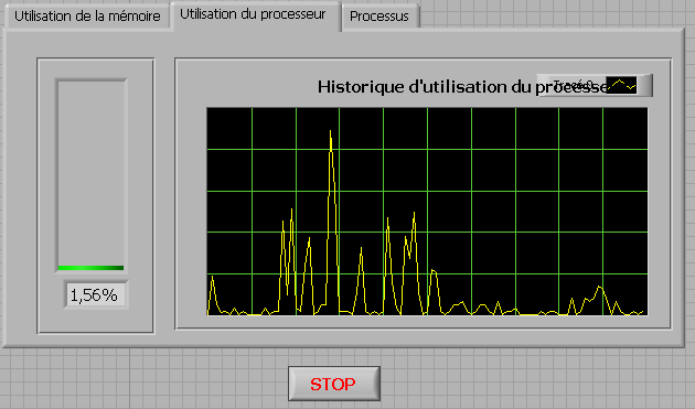
How to check the CPU usage and paging using LabVIEW
Hi guys,.
I build an application that is used to check the CPU usage and paging using LabVIEW. How can I do?
any help, suggestions or advice will be greatly appreciated...
Kind regards
Prashant
Hello
If you plan to build your app for Windows, you can use .NET classes. (System.PerformanceCounter), there is a simple example with LabVIEW:
C:\Program NIUninstaller Instruments\LabVIEW 2010\examples\comm\dotnet\SimpleTaskMonitor.llb
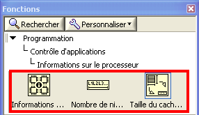
Also, you have several screws that you can use to verify information about the processor.
Kind regards
-
Programmatically insert step of ActiveX/COM using LabVIEW
Hello
I would like to be able to create sequences like the one set using LabVIEW.
This sequence has only 2 steps, a LabVIEW VI call and an adapter of ActiveX/COM call.
I was able to do using an adaptation of the code here: https://decibel.ni.com/content/docs/DOC-36337
However, I am struggling to add the step of the ActiveX/COM.
Any help would be welcome.
Thank you
Of course, there is a way, if you look for it
Since you have an existing 'Step' class object, you can also get a 'Module' object for her. Subsequently, you will need to specify that it is an ActiveX module. If you do not know which - probably you need to get the object 'map' somehow... Our case is simpler, so just cast to the ActiveX module and... to set certain properties like ServerId, ActiveXReferenceExpr and so on.
I've attached an example for you. Interesting thing is the ServerId - I just read this chain of the TS for similar action and reused it here so do not ask me how to get automatically
You will need to complete your 'properties' as 'file' - but I'll gracefully leave this work for you =.
Best regards
-
Time real ADC/DAC for SMPS by using Labview and USB
Hi all
I asked the Sales Department of this same question, so here's a two-pronged approach:
I am reserching a control algorithm for power switching, and so far, its performance simulations seem to be good. Now, the goal is to implement the circuit from the experimental data.
I've seen several NI USB DAQ boxes that seem to have the performance, I'm looking for (for example, the box USB-6211 a sampling rate and resolution I need).
The control algorithm uses the following mathematical functions: add/sub/mult/div/exhibitor and derivative/integral.
My question is this: is "strong enough" Labview take four-channel data 250Ksps, crunches the numbers in an equation and spits out the answer to an analogue on the channel, while time REAL? I'm looking for a rate of analog output of ~ 100 kHz.
Thank you for any suggestions you have!
-Rick
Hey,.
So if you were trying just to perform an input or output, then the box USB-6211 would certainly be able to treat it as the machine clock could manage the inputs/outputs, no software. However, what you are wanting to do, basically a feedback system, he will have to avoid (at least to a USB device) because you need to be able to specify Active which is the output. So, for this reason alone and the fact that you want out of 100 kHz, this device and the USB devices in general will be not an option any what software you use, LabVIEW or otherwise. On another note, you want to make sounds more like live update, not in real time, which is more on the jitter. Bottom line, for these kinds of requirements, you might need to move to an FPGA card, something like the NI PCIe-7841R would work. It's more expensive, but for your needs, FPGA will be the only option and it comes down to the latency of the bus, but also the response time of software. With FPGA, as shown in the first scheme of the following document, you basically close your software through hardware loop.
Basics of FPGA
http://www.NI.com/white-paper/6983/en
-Ryan S.
-
How to view mdsplus data using labview
I posted this question in the Council of Labview, but seems that nobody does it so far. I don't know what is the best place to ask this question. So I reposted here. Thank you very much.
I am a newbie to Labview. I'm writing a few vi to display and write data to Mdsplus. I downloaded Mdsplus(labview) can discover Mdsplus functions, like mdsconnect, mdsput, ect, in vi to call a library function. But I have no ideal how to use it. I tried to use the Mdsconnect function to connect to a machine, but it still gives me an error like: Labview: an exception occurred in the external code that is called by a call library function node... I was looking for help on the internet documents, but could not find anything useful. Could you please help me with this problem? If you have examples of these vi, or teach me how it, it would be very useful. I'm using Labview 8 (windows). I would appreciate your help! Looking forward for your reply.
Oops,
I attached properly in the previous post.
Greg
-
Cloning a hard drive using LabVIEW
I'm trying to clone my laptop 476 GB HDD for a 450 GB SSD. The data on the laptop HARD drive are about 350 GB total, so there should be. Each commercial application, I've tried has failed to be cloned for one reason or another.
So I thought, ' Hey, I have a development environment, I'll do my own cloning software in LabVIEW! I understand that sector-by-sector copy of data is extremely low, but is it possible to do this in LabVIEW? My research drew a blank.
Thank you
Malcolm
Yes, unfortunately you have almost 0 chance to be able to do it using LabVIEW (except trying to hang in an application that does) as LabVIEW is a high too high level language - all file system operations pass by and get handled by the operating system.
As others have said, you should reduce the partition first, before you can move the disk - many tools better cloning can do for you. Unfortunately, I don't remember the name of the tool, I used to do it on my laptop but I certainly heard of the Acronis software before. Make a copy of the file in the operating system will not work because it won't copy things like the boot sector information.
There are also a few layouts guard/traps around moving a HDD to SSD (for most around things like sector sizes) - it is useful to have a read around this before you start.
-
Good Aftrnoon.
My thesis is based on software developed by using Labview. Can anyone suggest the best way to write the main sections?
For example, how to describe the experimental flow? My ideas have been use explanatory, take the labview code print screens describing what each of the subVIs. Does anyone have experience in this field? Or if you can share a thesis based on LabView program written, it would be ideal for reference. Thanks in advance
Kiryl
If your project markers are not familiar with LabVIEW, then frankly they should not be monitored a LabVIEW project.
In the same way that you would not be supposed to literally print code of entire base of a project in a written language, you don't need to go into the same level of detail with a LabVIEW project.
You can document your code with system diagrams, annotate them extracts of interesting pieces of code, writing pseudocode to illustrate the feature.
Maybe you are looking for
-
iOS 9.3 data consumption above - Verizon
Everyone sees a spike in data since the latest iOS update on Verizon? Since August, I have streamed music to work, which is 45 minutes. My wife it broadcasts a few times, not as often as I do. We were on the plan 6 gig and NEVER had a problem. Now, i
-
Contact email list - I would only the contacts listed from A to Z by last names of each contact
I need help in the listing of my Email from A to Z contacts according to their surnames. Thank you
-
Two extensions of the range RE7000 with EA9500 router works not so well...
Everything works very well with a RE7000, but when I add a second RE7000 (needed for another part of my house with weak signal), the 5 GHz band is confusing. By "confusing", I mean that you can however connect WiFi, but for some reason Internet acces
-
I bought the S2340M from Amazon (back in July 2013) about 15 months ago. However, recently, I've been doing the red lines that appear on the right side of the screen and I can't get out. I set my monitor to the factory settings and ran the self test
-
Date of publication of Oracle 11.2.0.5 database
Hello, you know the 11.2.0.5 Oracle database release date?Thank you!!