[fpga] Configuration of analog input or 7965R
Hi all
I have a card FPGA NI FlexRIO (SMU-7965R) with an adaptation module (NI 5733). I'm using Labview real-time 2012. My measurements are dominated with harmonic sound of 60 Hz, which is most likely due to the ground loop. I try to put my analog inputs (as opposed to the CSR, NRSE) differnetial mode to try to overcome the ground loop. I came across this link which explains how to configure the FPGA input channels-
http://digital.NI.com/public.nsf/allkb/08EF26D2E9041BC6862570E0001E442E
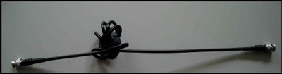
However, the installation program of the RIO device for my goal of opening, I found that there is no option to choose the channel configuration (as shown in the attached picture). This means that the analog channels are in differential mode by default? If this is not the case, how can I change?
Any help will be greatly appreciated.
Hello!
This KB is in what regards R, not FlexRIO product line series materials. I know it's a little confusing because the 7965 has an indicator of 'R' at the end of the model name, but the R simply it is a product with an FPGA that is programmable by the user.
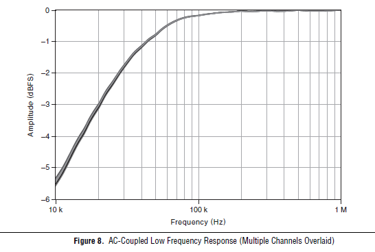
Unfortunately, the adaptation modules FlexRIO 573 x are all only ended then we will not be able to change to the differential. What is the frequency of the signal you're trying to measure? Another option would be to set the 5733 coupling AC mode, which would give the frequency response following, dramatically eliminating any sound below 10 kHz.
Tags: NI Software
Similar Questions
-
PXI-7831R configuration as analog inputs
Hello
I'm new on NI PXI, thought that I've worked on Labview. My PXI chassis has two modules analog output (PXI-6713 and 6733), a PXI-2501 FET multiplexer, a PXI-4070 DMM, PXI - 8464, an IEEE host module adaptation and the module a PXI-7831R reconfigurable i/o () .
I was able to properly configure my components using MAX.
The problem that I do exactly face 'takes analog input' using my PXI chassis.
With the modules above, I suppose that I can use the 7831R as analog I/o module.
But the problem is the 7831R is a FPGA module and it is not displayed in DAQmx.
So, where can I exactly find the analog 7831R pin (in the labview GUI) and how to use them in my block VI?
The next version of labview provides an interface to data acquisition even for 7831R? (my version of labview is 8.2.1).
Kindly help me to solve my problem.
You need the- module FPGA.
-
Several analog inputs with different configuration differential/CSR
Hello
Can anyone tell how to measure two analog inputs with different configurations using a USB-6009?
I am aware of the syntax for create virtual channels for the channels DAQmx create virtual so I created two strings using Dev3 / ai0:1 but I would like the first string of the CSR and the second to be differential.
So far I have found no way to specify the configuration of the separate channels.Any ideas much appreciated!
Jack
JackT wrote:
I prefer to use the 'low' level vi is therefore always curious to know if there is a way to set the configuration using the their.
It should be like this:
-
How to configure multi analog channels inputs in a single task
Hello I want to acquire two signals of the two channels (input 1 analog acceleration; analog input voltage 2) without using wizard DAQmx because I have to use standard vi I use usb NI 9234 any suggestion please I tried with a chanel and I got good result but when I try two delivery channels I errors please hep me
Hi Broutchoux,
What are the errors you get when you run your code? This is a mistake-50103? As long as your acceleration and your task of voltage use the same synchronization settings, you can combine the two channels in a single task. This should fix the error you receive. The article below has a picture that shows the configuration I describe:
With the help of different Types of Global DAQmx channels in the same task
http://digital.NI.com/public.nsf/allkb/3296BA2AEF586B7386256D6D00528E3D?OpenDocument -
PXI-6070E, how can I configure which are two analog input pins?
Hello
I'm reading 3 analog signals using PXI or 6070E simultaneously. I'm looking for on what axes correspond to what analog inputs? It's the same thing all the time, or should I set up?
For example, currently, the pines 68 and 34 are the + and - of the AI0 channel. But I can't find the rest.
Thank you.
How you are looking for the list of the pins? Look in the manual or in MAX, right-click on the device and select 'device pinouts. Ai0 is 68, ai1 is 33, ai2 is 65. The pins do not change. What changes is ending the pins to use if differential or single acquisition. For example, if you purchase a differential signal with ai0, you use pins 68 (ai0) and 34 (ai8).
-
Analog input and output using 5640r
Hello world
I'm Christine, I'm implementing OFDM on fpga using 5640r.
The code that I have, which is good in the simulation using labview and also using 'nor 5640r treatment only' but I want to implement in "analog input and exit vi" so that I can send and receive on the same card 5640r
After so much attention in this regard, I am still unable to find the issue, then the soultion to this question. something that I am able to understand that maybe there would be some questions (ADC and DAC) clocks the clock setting
I have attatched that vi. Please take a look at
Concerning
Aqib
College of aeronautical engineering
Risalpur
Sorry
-
6008 analog input - invalid values
Hello
Does anyone know how the analog input voltage 6008 invalid handles? Specifically, what happens if the circumstantial channel is configured for a 0 - 10 range v and a voltage negaitve, (-19.0) volts is placed on the analog input?
I use the library, C/C++, OR-DAQMx library. The call that I use to set up the port of AtoD is:
DAQmxErrChk (DAQmxCreateAIVoltageChan (taskHandle, AINPSTR, "", DAQmx_Val_Diff, 0,0, (float64) s_dMaxAnalogInputVoltage, DAQmx_Val_Volts, ""));
where: s_dMaxAnalogInputVoltage = 10.0;
and
DAQmxReadAnalogF64 (taskHandle, 1, 1.0, DAQmx_Val_GroupByChannel, values, 5, & not read, NULL);
to read the circumstantial.
What will happen if any illegal input voltage is applied. I know that everything is a wide range, so I don't talk about something like -60 to + 60 volts.
Thank you
-Neil shore
These specifications are in the datasheet of the product - link to it in the product specifications of the page tab.
And no, there is no error generated when the input is out of reach. Scaling the proper entry so that this doesn't happen. or if this is the case, your software recognizes that is higher than expected.
-
Problem with a precision of analog input on PCI-6111
Hello
I'm reading an analogue signal which varies from 0-11 V using a card of acquisition data PCI-6111. The signal comes from a Tube set (PMT) which is part of a microscope configuration, so it is very important that the resolution of the analog input signal be as wide as possible generate quality images. According to the data sheet for the PCI-6111, the analog input resolution is 12 bits, which should correspond to a sensitivity of ~2.686 mV for my voltage range.
To test this, I set up a task to analog input with a 0-11 V voltage range to read samples of an analog output, which I wrote a simple waveform. Since the 16-bit analog output resolution that I assumed that it would not limit the accuracy of this measurement. I have attached the VI I used for this measurement below. The analog input data are saved not truncated in a text file.
Analyzing these data, I found that the real input sensitivity is ~9.766 mV, corresponding to levels of voltage exactly 1126,4 and ~ 10 bits.
Is there a reason why the resolution of analog input is much lower that it is indicated on the card? What are some of the ways I could improve the sensitivity of this measure?
Best,
Keith
Sorry, when you mentioned the specs, I thought you already had them. If this did not come with your Board of Directors?
-
NIDAQmx to simulate synchronized analog input from two devices of simulations?
I would test synchronized analog input from two MFDs simulated from the NI6225. I created two devices of simulated able NI6225 & Automation (M & A) and tagged the first NI6225a and the second NI6225b. M & I created a RTSI cable configuration and added both simulated devices. However, when you call NIDAQmx C functions in my test code, I get an error condition indicating that the simulations devices are not synchronized. Before continuing, I would like firstly to confirm if NIDAQmx is designed to
simulate synchronized the analog input data of two devices of simulations. If this isn't the case, then it will explain the error condition that I have encountered in my test code.
Thank you
Ian
Hello John and Jared,
If I remember well used to support the simulated synchronized devices. I ran various tests this week, but all fail. I'm going to order/install a RTSI cable and test with physical devices.
Thanks for your help. I close this post.
Ian
-
The use of more than 16 analog inputs of a module?
Happy new year to everyone.
The analog input module OR-DAQmx can only support up to 16 channels. Now serveral DAQ cards provide more than 16 channels, including PCI - 6259M offer 32 entered analog.
So, how do dasylab (Ver 11) support more than 16 channels in a NOR-DAQmx analog input module?
Hello srm2003,
(1) build your task NI MAX for your camera - 6259 - 01.png.
(2) DASYLab: Take a first OR-DAQmx analog input module, choose the task of MAX and configure the channels 0... device 0 15... module 15 - photo 6259 - 02.png.
(3) DASYLab: Take a second NOR-DAQmx analog input module, choose the task of MAX and configure channels 16... device 31 0... module 15 - photo 6259 - 03.png.
(4) now you have 2 HAVE modules to manage channels 0... 15 (first) and 16... 31 (second).
Best regards
MHa -
USB-6211: analog input signal affecting another of the same map AI
Hello
I use the DAQ-nor-6211 map and DAQmx features to read a hammer and a signal of the accelerometer and then use other LabView functions to make the FFT of these analog input signals. However, it seems that the analog inputs where the hammer and the accelerometer are connected generate a kind of noise or influence in other entries of this data that is not connected to any other sensor acquisition board.
I've had different experiences in order to check if the problem is with reading the card: put the accelerometer and hit the dog in another table where the DAQ card table was located (to avoid the vibrations on the map and a possible noise), ai1 entry was logged on the differential mode on the dog and the ai4 of entry is connected to the output (z axis) of the accelerometer. The other 2 ai2 and ai3, entries that can also be read by my LabView program, are open (i. e., any other sensor is connected to the card). When the structure where the accelerometer is located is struck by the hammer, the signal of ai2 ("x axis" seen in the first attached document) has a curve (on the time domain) which initialize almost at the same time that the hammer and the a3 of entry has a weak signal, but with the swing as well as the signal of ai4. The document "hammer ai1 + z_axis connected_ _x_axis disconnected ai2 + y_axis ai3 ai4" images that I captured the chart created in LabView. On these graphs, it is possible to check on the FFT the ai3 signal and ai4 has the same behavior (with different intensities), and enlarged figure of time domain image, we can see that the signal of ai2 increase almost at the same time of the signal of the hammer (ai1). The signal picked up by the sensors are probably creating a sort of noise on open entries ai2 and ai3.
Another experiment was conducted to check if the signal from a single entry that may affect the signal read from each other near the entrances: the DAQmx task Create channel had a physical channel has changed: ai3 entry has been modified by ai7 (maintain the same connection mode: differential), and the results are visible on the second attached document. In the graphs obtained in this experiment, it seems that the entrance of the hammer (ai1) affects the signal of input ai2 and ai7, which are not connected. And the ai4 signal does not seem to influence the other inputs, because he has a different curve on the graph of the FFT.
The same experiment was conducted using the CSR connection (change threads and create the DAQmx Channel Configuration), but the results were the same as those found using differential connection.
Finally, if the output of the accelerometer is connected on the ai2, the signal of the other open entries ai4 and ai7 seem to be affected by the signal of the accelerometer on ai2 (last document attached).
Could you tell me if the problem I encounter is caused by the DAQ card with this information that I gave to you? And if the answer is Yes, do you know if there is a way to avoid this noise create in one entry on the other hand, it please?
Thank you
Maybe Ghosting or crosstalk? Just an idea.
-
Continually acquire analog input, internal clock, break, Multiple device
I have a PXI chassis with 6 cards SMU-6363. I want to acquire data on the channels of each SMU-6363 map continuous AI, using the internal clock for timing. I need to use a trigger to pause reading of a DI on one of the cards SMU-6363 for a break and to reactivate the acquisition. I came across this example: https://decibel.ni.com/content/docs/DOC-12256/ , but keep getting error-201019 DAQmx start task "trigger break is not supported in a task to more devices. To configure the start of break in a multi-device configuration, you must use no more than one device per task and route manually clock in demand signals. »
The problem is that the configuration of I is made during execution by the operator. Sometimes they want to acquire data on one HERE through all 6 cards SMU-6363, sometimes they want to acquire data on each channel of AI through all 6 cards SMU-6363. What makes the task definition until manually route clock signals between devices for each rather difficult task.
Is there a simpler way to solve this problem?
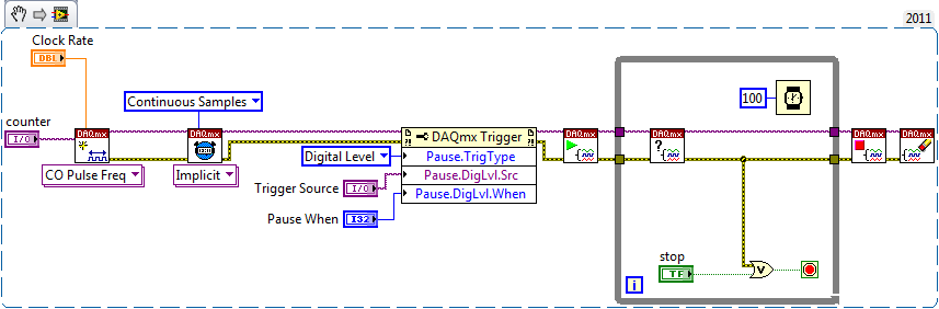
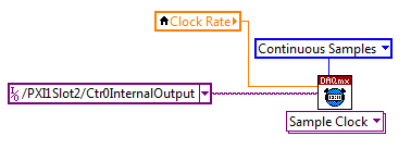
Set a task to output counter - something like this:
Next, configure your task of analog input to use the sample clock output of the meter:
Best regards
-
Analog input problems using PXI-6232
I tried to solve this problem for a while now without a bit of luck. Solution suggestions are welcome.
I use a PXI-6232 with LabView 8.5.1 to accept signals analog several of my sensors. Based on the signals as a PWM signal is generated and the output using PXI-6713.
Some of the analog input signals have spikes in them, which occur at all times during the tests. I watched the same signals on an oscilloscope - without crampons. I change my hardware configuration, and the spikes still occur in the same places. It seems that the program makes some resets resulting in measurement errors.
I have attached the VI and a JPEG of measured inputs.
Thanks in advance
Concerning
Vadim
I was first confused of your time scale
 but it seems that these spices occur every 20ms (not s) what to a line 50 Hz noise due to switching power converters (or a diode without compensation bridges
  )
)Another clue was the measure of the scope. While using the application scope, you opened a groundloop so the spikes because of the dI/DT through the groundloop are another way to get around.
So I'm pretty sure this isn't data acquisition (in this case) this is your configuration.
Provide a cleaning (low R AND L low) path of power (keep them close and twist slightly if possible), add a filter to down the dI/dt, identify the ground loops. (Use your scope with a little as a sensor at the entrance to reel and catch magnetic fields can open eyes)
THEN to clean the last ears (on the acquisition of data) to get the last ppm use selfs
-
What is the minimum response of analog input, through DSP online, output analog time?
Hello experts!
I want to know if it is possible to get a very quick response latency (~ 1 ms) sound recording (analog input), through online registration (DSP online), the presentation of his (analog output) processing, by using the DAQmx programming codes. My system of NEITHER includes NOR SMU 8135, SMU 6358 DAQ Multifunction controller and SMU 5412 arbitrary signal generator. I also have access to the latest version of Labview (2015 Version) software.
My project is on auditory disturbances, which inovles record vocalizations, manipulating the recorded vocalziations and then present the manipulated vocalizations. My current idea of how to achieve this fact triggered output voltage after reading the input using DAQmx Read samples. DAQmx Read output is filtered online and then passed as input for the DAQmx writing for analog output. For purposes of illustration, examples of code are presented below. Note for simplisity, codes for the trigger part are not presented here. It's something to work in the future.
My question here is If the idea above should be reaching ~ 1ms delay? Or I have to rely on a totally different programming module, the FPGA? I am very new to Labview so as to NEITHER. After reading some documentation on FPGA, I realized that my current hardware is unable to do so because I do not have the FPGA signals processing equipment. Am I wrong?
Something might be important to mention, I'm tasting with network (approximately 16 microphones) microphones at very high sampling rate (250 kHz), which is technically very high speed. Natually, these records must be saved on hard drive. Here again, a single microphone is shown.
I have two concerns that my current approach could achieve my goal.
First, for the DAQmx Read function in step 2, I put the samples to be read as 1/10 of the sampling frequency. It's recommended by Labview and so necessary to avoid buffer overflow when a smaller number is used. However, my concern here associated with the latency of the answer is that it might already cause a delay of 100 ms response, i.e. the time to collect these samples before reading. Is this true?
Secondly, every interaction while the loop takes at least a few tens of milliseconds (~ 30 ms). He is originally a State 30 late?
Hey, I've never used or familiar with the hardware you have. So I can't help you there.
On the side of RT, again once I don't know about your hardware, but I used NOR myRIO 1900, where he has a personality of high specific speed for the RT where I can acquire the kHz Audio @44 and process data. Based image processing is ultimately do the treatment on a wide range of audio data you have gathered through high sampling frequency and number number of samples as permitted by latency, please check this .
I lost about 2 weeks to understand host-side does not work and another 2 weeks to understand the even side of RT does not work for online processing (real time). Then, finally now I'm working on FPGA, where the sampling rate is 250 kHz (of course shared by multiple channels).
The complex thing with FPGA is coding, please check if the filter you want is given below as labview automatically generates some codes of some filters.
Most of them will work in 1 SCTL IE if your target has 40 MHz clock algorithm will run in 25 ns. That's what I was looking for, I hope you

See you soon... !
-
15-20 time of latency to see the changes in analog inputs
I inherited a program extremely complex. I find that I see 15-20 seconds latency on the changes to the analog inputs. I can't post the code - (it has more than 200 sub screw) but I have captured the relevant section in the long latency period of the changes.jpg of analog input attached.
I tried to change the sampling rate and see the same problem from 1 Hz to 25 Hz (limit of reliable sampling with this PC). I'm looking at indicators which are directly related to the acquisition of data Read.vi as evidenced by the big red arrow.
I modeled the nested struct in the template attached without latency problems.jpg. There is no perceptible latency but it duplicates the nested structures.
The only thing not shown is that there are several cases of Read.vi of data acquisition using the same physical changes but not of them are in the loops that need to run at the same time.
The data are consistent with the entries, just delayed.
The Signal processing device is a USB-6343. I am running these screws on LabVIEW 2011 edition.
Any ideas?
Yes, instead of getting just 1 sample buffer, try to get all the samples.
Then you can retrieve the most recent example of all the samples you get and take the rest of them.
Or you can change the configuration of taks for only once every time that you call the read function.


Maybe you are looking for
-
The lightning disappeared. Was working fine before.
Can not find a way to recover.
-
How to find the history of purchases
I have many recipes in the history of the purchase, how to search by keyword to find a?
-
Siri free eyes - 2016 Jeep - anyone having problems?
I just took delivery of a 2016 Jeep Grand Cherokee. One of the important reasons that I ordered it was the new command button "Siri eyes-free. As many of us know, iPhone users have not voice full of e-mail/text in some systems of the car. Until CarPl
-
I saw messages about this before, but most have been dated around 2010 or more.Anyone got a W700 to work, I mean start and such, but if it's important, Win7 Pro x 64, say with 16 GB of RAM? That's two sticks of 8 GB. How about 2 x 4 GB to 8 GB of RAM
-
Cannot set the homepage in IE 8
I was recently infected by the virus 'Internet Security 2010' rogue / problem. I ran Malwarebytes Anti Malware program and got rid of it and also to launch a program to solve the persistent problem of not being able to launch programs. I have a pro