FPGA CRio do not give good digital outputs
I'm working on a project with the compact RIO fpga. I tried following the youtube tutorials and written tutorial, but I get no similar results in scanning FPGA interface.
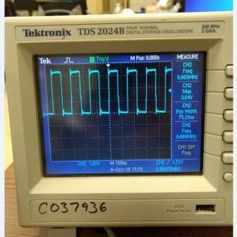
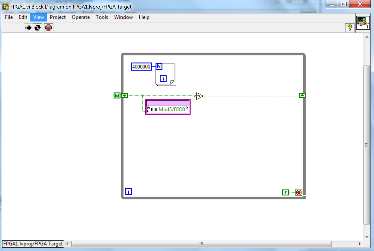
I have attached my project. Here's the signal that I get from the Basic VI, which is a digital IO defined as output in a while loop. Alongside this, there is a loop for fundamentally changing the frequency of the digital signal from the top down. But whatever number I put in the loop for, it gives me the same frequency.
My thought process goes like this: If the CRio has a processing time of 40 MHz to a loop that cycles 400 times should give me a swing of 100 kHz output, which is not any number, I put in.
Any help is appreciated.
Thank you.
LabVIEW is almost certainly that compile to loop out like dead code (nothing happens so LabVIEW gets rid of it). I advise to use the loop timer function if you are looking to change the frequency or put everything in a timed loop. All in a timed loop will execute a tick.
Tags: NI Software
Similar Questions
-
USB-6008 to give the digital output
Hi all
I was wondering anyone at - it base an example of an exercise using USB 6008 to give a digital output of a VI in Labview.
I am very new to the use of the USB 6008 AND Assistant DAQ and so far I've had reading a temperature, next step is I want the USB-6008 to give a + 5v output when the temperature reaches a certain value, I built a Labview 2009 VI for the temperature reading, but now I'm stuck on this piece.
Any help is appreciated! or if there are examples of laboratory exercises that exist that I can perhaps draw.
Hi Marko
Please take a look at the link that has some interesting and intuitive video to use the USB-6008 housing and how to set up the device for several applications in LabVIEW below. Please take a look at the step by step videos and let me know how you go. They are under the tab '"virtual Demos.
-
measure your does not give 0 for output
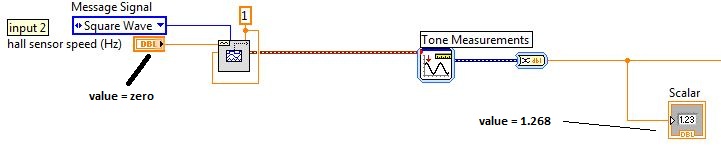
Hello all, I use the tone for measurment.vi measure the frequency of a square wave from 0 to 15 Hz. when I run my program, my square wave frequency is zero, but the output
the your measurment is 1,268, while running the program I get the value to zero. but it is very important that the start value is zero. I hope someone can help me with this.
Thanks in advance
kapoew
-
PCIe-7842R (series R FPGA) digital output does not work properly
Greetings,
I'm having some problem show TTL the correct voltage with my PCIe-7842R FPGA board.
The block diagram of my code FPGA LV Moose appears in "analog - digital .png '. The idea was to convert an analog input (decimal value) to a binary code and 16-bit output by 16 DIO ports. I use the connection block SCB-68 has as the terminal and trendy on the FPGA 1 connector RDIO with SHC68-68-RDIO shielded cable.
The compiled code ok. But during the test, I noticed that some ports has no output TTL levels correctly. For example, for input 1000 decimal, I would expect binary code 0000001111101000. However, some ports (DIO #6, #7, #9, etc.), which are supposed to ~3.3V (1 digital) high TTL output, output actually 0.8V. I have attached the result measured in 'exit digital test.png '.
To ensure that the question was not because of the code of the LV, I did some more tests on DIO #6 with a simple example (simple digital output.png). The output was ~ 1V this time at the digital 1.
It's really confusing because of the digital Edition is supposed to be simple. I used the same FPGA card for controlling roller shutters with TTL signals before and it worked fine.
Does anyone have similar problems? Any suggestions are greatly appreciated.
iron_curtain wrote:
DIOs are connected to a controller digital galvo Cambridge Tech. But I measured the voltage at the terminals of the connector block.
If you unplug the controller galvo DIOs, do they look good (have the right voltages). Do you know how many of these entries to the need for controller? I think you hit the limit the total current available for EID within the Council.
-
Fortunately the cRIO merger two time real screws: analog and digital output
Howdy,
I need help with a cRIO code. The purpose of the code is to acquire an analog input from the NI 9234 c series module and be able to send a "signal of pulse" digital camera (first low for some time, t1, then high for some time, t2) from a NI9401. Separately, I wrote the code to perform both tasks. However, when I add the code of RT digital output pulse pulses to analog input RT code, the DMA FIFO overflows because of the way that my digital pulse output code works. Currently, there are two reasons which overflows of the FIFO:
- The digital output code is pending for a while loop (pending "Send Pulse" become a true), the loop I can't empty the buffer FIFO
- The FIFO is not enough, quickly emptied depending on how long the pulse (t1 and t2) times are. The way I keep the pin high or low for a defined period of time is by issuing a sleep command, which blocks the loop I empty the FIFO. (Is there a "best" way to sleep?)
I have attached photos of my codes FPGA and RT. Please give me a suggestion on how to marry my two loops of RT for the use of happy resources! Thank you.
I found a quick way to solve this problem. I moved the timing of the Digital pulse on the FPGA. So whenever I have a Boolean value, the FPGA generates a waveform with the settings I put (a pulse in my case). This works because the FPGA loops run in parallel, I think. That's why, when I run a pending order in the loop of FPGA digital output, it does not prevent the FPGA of analog input loop to run. I have attached a picture of the code.
-
Digital output is not 5V when connected to a circuit
I have a very simple circuit I want to operate a valve. I have a NI USB 6008 with 12 digital i/o ports, a KF0602D solid state relay, 12V power and a solenoid valve.
The idea behind this circuit is pretty simple: use a digital line of the 6008 to close or open the switch in the KF0602D. With the switch closed, current flows from the power supply through the switch, to the valve and that opens. When the switch opens no current flow and the valve closes.
When I plug my 6008 in the KF0602D, however, my 'high' digital output falls from 5V to 1.73V. It's a problem because my switch requires at least 3V to close. I don't know why the voltage decreases because the relay is supposed to just on 3mA current with an input 5V, wells in the area of the specs listed 6008. What can I do to make this work?
Outputs digital USB-6008 are drain opened with pull-up 4.7 kohm resistors. This will NOT lead your SSR entry requiring > 2 my.
He must reverse the polarity of your control signal. Wire-entrance of the Republic socialist Soviet to the line of the 6008. Wire the + input of the Republic socialist Soviet to + 5 V. Then you have the 8.5 my driving ability to do what you want.
Lynn
-
USB-6211 - digital output not supported?
Hi all
I can't use the USB6211 device port... I use daqmx with Delphi7 API functions.
First of all, I tried this:
DAQmxCreateTask('', @TaskDO);
DAQmxCreateDOChan (TaskDO, PChar('Dev1/port0'), ", DAQmx_Val_ChanForAllLines);
DAQmxWriteDigitalU8 (TaskDO, 1, 1, 1, DAQmx_Val_GroupByChannel, $FF, @written, nil);I had an error in the DAQmxWriteDigitalU8:-200012 (= digital output not supported). (???)
OK, I tried to disable autostart option based on DAQmxWriteDigitalU8 and insert a 'manual' start in the code:
DAQmxCreateTask('', @TaskDO);
DAQmxCreateDOChan (TaskDO, PChar('Dev1/port0'), ", DAQmx_Val_ChanForAllLines);
DAQmxStartTask (TaskDO);
DAQmxWriteDigitalU8 (TaskDO, 1, 0, 1, DAQmx_Val_GroupByChannel, $FF, @written, nil);
DAQmxStopTask (TaskDO);Now, I got the same error in DAQmxStartTask:-200012 (Digital Output not supported, once again). (?????)
I don't understand.. 'Digital output not supported "? USB-6211 has 4 lines! What is the problem?
I want to just turn on and off the lines from code...
-Cs George-
Well, finally I figured out...

Here is the solution:
DAQmxCreateTask('', @TaskDO);
DAQmxCreateDOChan (TaskDO, PChar('Dev1/port1'), ", DAQmx_Val_ChanForAllLines);
DAQmxWriteDigitalU8 (TaskDO, 1, @dummy, 1, DAQmx_Val_GroupByChannel, @bitmask, @written, nil);Digital output lines are on port1! Corrected parameter.
And the part of the interface of DAQmxWriteDigitalU8 had to be changed (in nidaqmx.pas).
I don't know why, but the AutoStart (dummy) parameter in the DAQmxWriteDigitalU8 function is ignored: function always starts task automatically, regardless of the value of autostart. But this isn't a problem for me.-Cs George-
-
What is a digital output (DO) good for?
Actually, I wanted to use the outputs digital to move from a 24 VDC circuit (to turn on/off other devices etc.).
But the current output outputs digital is so low that I have even impossible to pass an opto-coupler (opto isolator).
That's why I wonder you use outputs digital for if you cannot use them to change anything?
Of course, I can create a circuit MOSFETS or transistors to switch 24VDC power with the TTL 5V digital output signal. But I guess that most of you do not :-)
And of course, I know that I can buy OR relay modules/cards. In fact, I have many digital outputs available and do not want to buy new modules/cards.
Now, I can test and actually I get 10mA @ 5V on a digital output of NI 9401 (DIO), using the digital output to pass an opto-Coupler.
It seems that the information contained in the data sheet are supposed to mean something else...
-
NI USB-6009 digital outputs are active when connected to a PC - I'm not that
I have a small problem:
All outputs digital NI USB-6009 module become active when the module is connected to a PC when no VI is running.
As soon as I start my VI, which controls the module, all the outputs are disabled (now inactive).
How can I achieve this, outputs are inactive if the module is connected to a PC with no program running?
johanneshoer wrote:
I have a small problem:
All outputs digital NI USB-6009 module become active when the module is connected to a PC when no VI is running.
As soon as I start my VI, which controls the module, all the outputs are disabled (now inactive).
How can I achieve this, outputs are inactive if the module is connected to a PC with no program running?
The USB-6008/6009 case has a pull-up internal (4.7 kOhm) resistance. This causes the outputs digital on the device to have a startup logic high State. t is not recommended to use some sort of resistance of menu drop-down. However, what you can do is add octal buffer like the 74HC541 stamp and a digital output to control the sorting of the 74hc541 state mode. Connect the OAS and CEO input signal. A Summit on the pins of the latter will be sorting the output of the buffer State. Therefore, no output signal will be present until you pull the stems of low control. The USB-6008/6009 case have a 5 volt output (200mA max), you can use the buffer.
-
Why my digital output give 1V instead of 5V?
I have a PCI-6030E. When I look at its digital output to port0/$line0, I see 1V instead of 5V when it is 'high '. He read 0V when 'low '.
Any ideas?
Amit
The only other thing I can think is that you don't have a good connection to DGND during the measurement or the line is maybe configured as an input. If this isn't the case, the card may be faulty.
-
Original title: unplugged... HDMI?
So I have a laptop Vaio of microsoft. The microphone that was integrated into the laptop was working fine until recently. No, I talked through my laptop was able to hear me except through Skype. I search through my laptop and say something like in the playback than digital output device or interface (HDMI) was disconnected. I know very well that I unplugged it. Can someone please?
Hello
1 did you change on your computer before this problem?
2. you receive an error message?
3. What is the exact make and model of your laptop?
4. are you able to record from Microphone?
5. which version of the operating system is installed on your computer?
What version of the operating system Windows am I running?
http://Windows.Microsoft.com/en-us/Windows7/help/which-version-of-the-Windows-operating-system-am-i-running
Make sure that the Microphone settings are set up correctly.
a. right click on the Volume icon in the notification area.
b. go to recorders and right click on the empty area.
c. Select Show disconnected devices and show disabled devices.
d. right click Microphone, and select activate.
e. Microphone right click and select Properties.
f. Select the option use this device for the use of the device falling down.
g. go to the levels tab and move the slider to the maximum level.
h. click on apply and OK.
See also:
Tips for solving common audio problems
http://Windows.Microsoft.com/en-in/Windows7/tips-for-fixing-common-sound-problems -
I use a PCI-MIO-16-1, and I'm trying to create pulses on each of the three digital outputs, using a hardware trigger. I got a solution that sort of market by using a loop timed; the loop runs once per trigger, and inside the loop, I use avoiding to turn each of the three outputs at the right time.
However, the problem is that the 1ms resolution of the timing of software is not good enough. So I try to find a way to do it using equipment, so I can get a finer resolution.
What I tried to do recently is to create a redeclenchables on one of the counters pulse train (using the example generate digital Pulse Train-finishes-redeclenchables) and use it as a trigger for the timed loop. I can get the pulse train to give me three ticks for every time that I get a hardware trigger and then put a state machine inside the loop to turn each of the outputs. (I am currently divide the material into three equal segments trigger.)
However, although I can generate the pulse train very well on one of the counters, I can't manage to get the timed loop to use this counter as its source of the moment. How can I do? Or does anyone have a better idea how to do that?
Unfortunately, the card you have does not allow for hardware timekeeping DIO. M series and recent X series Multifunction DAQ devices allow such a task. If you want, I can have a technical representative contact you to discuss your request and provide appropriate suggestions to optimize your application.
Kind regards
Glenn
Technical sales engineer
National Instruments
-
Realtek integrated sound card is stuck in digital output
I can't get this thing off the digital output mode. Now I have no sound because all analog ports do not work. Telling me that nothing is plugged. I can't reset the analog speaker because it is grayed in Vista. This problem seems to be very common with computers using Realtek and Vista, just do a google search and see for yourself.
I have a feeling it has software problem between Vista and Realtek. But I really think Realtek is just terrible to began with and should not be put in any period of the computer. If I can't get this thing works here tomorrow I will get a good real map.
Message edited by hn333 on 09/04/2009 21:02I had very similar problems and finally managed to solve it.
Something seems to be borked with drivers realtek about automatic jack detection.
After attempting to use the method described here (easier if you can) http://freeweelee.wordpress.com/2008/12/09/vista-and-realtek-front-panel-audio-not-working-solution/, I discovered that I was completely unable to cut jack detection in audio Manager Realtek (no folder icon).
For those of you who (like me) have no icon file, I managed to find another way to disable the detection of jack.
Using the registry editor, find all instances of ForceDisableJD and change the value from 00 to FF.
After making sure that I got all of them, I was able to reboot and everything works fine now.
-
Hallo,
I use the following system:
- OR PXI-1044 with controller NI PXI-8109
- OR PXI-2564 switch module to turn on the monitor of my test device
- Data acquisition multifunction NI PXI-6259 to measure the signal that responded to the questionnaire jump
The two cards are the same - PXI trigger bus. For both, PXI-2564 and PXI-6259 I use DAQmx to set the reading and writing of the channels.
Now, I want to measure the time between the digital output, my unit turns and the analog input, which measures the response of my system.
I can't do work by myself, please help me!
I thank Ludwig.
Hi Ludwig,.
If you can't give us any VI we have difficulties with to help you.
Because I Donat knowledge how your program is mounted it is not easy to know where you should enter signals.
Here's a question similar to yours:
http://forums.NI.com/T5/LabVIEW/best-way-to-measure-time/TD-p/178704
and 2 external links:
http://www.ehow.com/how_8698983_measure-time-LabVIEW.html
http://objectmix.com/LabVIEW/385152-how-can-i-use-LabVIEW-measure-time-between-analog-pulses.html
-
Digital output with timer (Simulation)
Hello everyone, I just found out how LabVIEW program a week ago. I try to do a simulation of digital output by LabVIEW (my attachment). In this simulation, I have a slider as an input (0-10 V), two digital controls (upper limit and lower limit), a waveform graph draw these 3 evaluates and two Boolean LED (P0.0 and P0.1) as indicator. In this simulation, you can fill any number (between 0 and 10) in numerical order as a limit for your entry cursor. If the entrance of a cursor exceeds these upper and lower limit, then the Boolean LED lights, P0.0 so exceeds the upper limit, and if P0.1 exceeds the lower limit. The problem is that I do not know how the timer for those Boolean LED. As an example:
(1) make an entry of cursor,
(2) if entry (1) exceeds the upper limit, P0.0 lights for 5 seconds, then turn to during 10 second.
(3) if only 10 seconds, you change the entry back to normal (between high and low limit) then P0.0 will stay turn of until the cursor entry exceeds the upper limit again,.
(4) If, in this second 10 you has not changed the entry (the stay exceeds the upper limit) then P0.0 repeats the process (2) until you the entrance to cursor back to normal.
(Same process for entries exceed the lower limit).
Can you help me do this timer? Thank you

Concerning
Juventom
Hello
If you don t mind I would just give you some advise to your code. To determine the data stream you can also use only the error wire connected to the loop. So Don t you really need, it's beter not not to use variables. For your solution, you can use something similar to what I tried for the upper limit in your program. It is added as an image.
Hope it helps
Maybe you are looking for
-
Password encrypted ticket to principal-protected or is security authorization simply in function?
Result, the safety of this new feature of file system permissions, or are password encrypted notes?
-
Characteristics of vision assistant
I was wondering if someone could tell me how to change an image´s brightness, contrast and histogram with vision assistant. I want to do this, in order to normalize the image and reduce the impact of the light on the image. I m of the system developm
-
Will be replaced by Skype Messenger MSN messenger?
Since Microsoft acquired Skype, MSN messenger will replace Skype messenger? Will there be a new addition to the areas of messaging that is, @hotmail.com, @live.com, @msn.com... and the new @skype.com? I'm looking forward to these changes.
-
How do I share a drive so it can be mounted on a computer running Windows 7?
I have a slot machine WinXP SP2 (for various reasons, can not upgrade to SP3). I have a hard drive on I want to be able to mount it as a network drive on another computer. On this other computer, I am using Windows XP. I have accounts of administrato
-
Hi, I am using: HP - PAVILION - 2000-2110TU. I am using windows 7 ultimate. My bluetooth does not work. When I troubleshoot it, it shows sm bus controller is missing. Pls help me.