Frequency measurement of analog input using DAQmx C APIs on SMU-6341 map
Hello
I use Linux DAQmx and attempt to measure the frequency of analog input using the map DAQ SMU-6341.
There is an ANSI-C frequency measurement example:
/ usr/local/natinst/nidaqmx/examples/ansi_c/Analog_In/Measure_Frequency/Cont_Freq-Int_Clk-SCXI1126
However, the call to DAQmxCreateAIFreqVoltageChan results in the following error:
DAQmx error: selected physical channel does not support the type of measure required by the virtual channel you create.
Create a channel to a type of measure that is supported by the physical channel, or select a physical channel that supports the type of measure.
Property: DAQmx_AI_MeasType
Required value: DAQmx_Val_Freq_Voltage
Possible values: DAQmx_Val_Current, DAQmx_Val_Resistance, DAQmx_Val_Strain_Gage, DAQmx_Val_Temp_BuiltInSensor, DAQmx_Val_Temp_RTD, DAQmx_Val_Temp_Thrmstr, DAQmx_Val_Temp_TC, DAQmx_Val_Voltage, DAQmx_Val_Voltage_CustomWithExcitation
Task name: _unnamedTask<0>
State code:-200431
DAQmx does support the function of the frequency on the map 6341, or should we use examples of voltage and calculate the frequency manually?
Frequency of HAVE it is a type of channel that has been supported only on the SCXI module name of the example.
You will need to use a voltage input channel and calculate the frequency manually for your device.
Tags: NI Hardware
Similar Questions
-
Medium-sized dynamic data analog input read DAQmx read
Hi, I'm new to labview. Is there an easy way to index using the dynamics of data returned by a readout DAQmx x samples to calculate a moving average? My thought was to read the analog input for X samples pump with the data in another loop through the data, but I can't quite understand how index using the returned data set to extract the measurement value double returned for each sample.
Any ideas on that?
Thank you...
If you get a type of waveform data, why did you ask on dynamic data? No, of course not would you use the conversion of dynamic data on a waveform.
If you want only one channel, then your DAQmx Read could be changed to 1Chan NSamp. If your channel list only has one channel, you will get a table 1 d with a single element that can be indexed. To get the average of a waveform use the statistical function with the waveform. You use the average Point by Point, and not the average function that has a table for an entry.
Make sure you always have context-sensitive help on. You can avoid many of these rookie mistakes simple.
-
How can I pause and resume the analog output using DAQmx?
I use a DAQ hardware to produce an analog waveform. I would like simply to break the output of the wave and then resume where it left off. I use DAQmx and LabVIEW 2011.
I've seen examples that use a digital or analog break trigger, but I would take a break in the software only. How can I do this?
-Joe
Hi Joe!
I spent some time thinking about it and I realized that you can technically use a fundamental mission of the analog output, as you previously wrote that runs continuously. However, the generated output samples are controlled by the sample clock pulses, and can be manipulated to fit our needs "suspension."
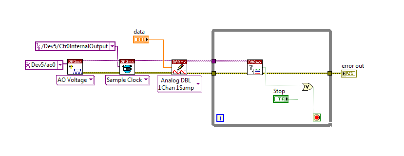
To do this, we will need another counter task that generates a pulse train (see our examples of shipping under material input and output > DAQmx > generating digital pulses > generate dig Pulse Train - Continuous.vi) that stops and starts the user to choose. This can be in another quite VI or controlled by software. We will use this as the task of our output sample clock.
Then, the task of the AO, wire a constant to the sample clock source and select ' DevX/CtrXInternalOutput"based on the counter that you specified in the task of counter. You will need to choose "I/o name of filtration" and check the box that says "include advanced terminals' and right-click of the constant. See picture attached as a reference. In this way, the task of the AO is constantly running, but it generates only actually all data when the meter running task.
Let me know if you have any questions!
Have a great day!
-
Need to read a 30, 1.5 a analog input using a NOR-9205
Problem: I need to read two analog inputs with good resolution using a C-Series card. The two beaches of signal are 0-30 V @ 1.5 and 0-5 V (not sure of the current). I need to be able to read the signal 5V with a precision of mV (or 16-bit resolution).
I looked at the module-9221, which works very well with the 30V, signal, but does not have enough resolution for the 5V signal. The 9221 is 12 bits on the beach of 60V.
I looked at the NOR-9205, which works very well with the 5V signal, but it cannot process the higher V 60 signal.
If a voltage divider circuit comes to mind, but has anyone found a good solution to this (other than to get both modules)?
Well, the current should not question. The entrance of the analog device (ideally) should draw no current and everything running on the source will cross the UUT.
A 4:1 voltage divider should evolve the signal to 9205 AI as long as you do not violate the absolute maximum voltage between a pin of the device and the Earth.
-
Analog output using DAQmx task
I need a signal to analog waveform using 6259 output, I followed the instructions to "Build an analogue output VI in NOR-DAQmx" in the developer area OR, when I run the code I receive thefollowing error message
"Error-50103 occurred in the DAQmx write (analog 1-d Wfm NChan NSamp) .vi:3.
Possible reasons:
The specified resource is reserved. The operation could not be performed as indicated.
Task name: _unnamedTask<1A> '
and when I press "continue" it goes ahead and track waveform on the front panel, but do not display it on the test panel in max could someone suggest how I might solve the problem?
Hello
Could you try the attached VI and let me know if it works?
I noticed that you receive information of the waveform sample clock, but the type of dynamic data that you use has no data of time in it!
-
How to measure multiple analog input at the same time.
I tried to do a VI that controls a motor with two buttons. If I press the buttons, the VI took the analog signal from the buttons and the engine is running. Each button covers the different direction - to the left and to the right.
I need to enter the two report in the VI at the same time, but I can't. If I run the VI, VI takes only a random signal. I want to know what are the problems and how to solve them. Please help me.
You must use a single task for both channels. See if that helps.

-
How to use DAQmx Read to measure several analog channels
I have two analog inputs using USB 6221 and I want to measure the voltage of each of them. I use vi DAQmx-read and I select input analog, 1 sample, several channels, but I do not know how to connect several channels at the entrance of the physical channel.
Hello, Bernadette.
For reference - I would recommend ad DAQmx questions here:
NEITHER Forums: Multifunction Data Acquisition
http://forums.NI.com/T5/Multifunction-DAQ/BD-p/250
There are several ways to add multiple channels for a fast task-ni.com look for "select multiple channels DAQmx" gives me this like the hit albums:
2X8D7F5Z knowledge base: How can I select more than one channel of NOR-DAQmx LabVIEW?
http://digital.NI.com/public.nsf/allkb/A3A05920BF915F1486256D210069BE49
Hope that helps!
-
6036E PCMCIA + DAQmx (analog input) seems to only read in blocks of 512 samples of data
Hello people,
I ask this question before I post any code or software versions etc to see if there is a simple answer.
I use a PCMCIA card 6036E to read an analog input channel (DAQmx... i. e create task, create the channel, set the altimeter (continuous samples), task, read in a programmed software loop while (ASAP)). No matter how I put my sample rate, number of samples per channel (i.e. size of buffer), or the number of samples to be read, it looks like I can get multiples of 512 samples.
Here are some samples freq (Fs), the 'number of samples to read' asked and the actual number of samples read:
FS numberOfSamplesRequested numberOfSamplesActuallyRead
200Hz 20 512
1000 1024 5000Hz
2000 2048 5000Hz
QUESTIONS RELATING TO THE:
1 is this 'normal' behavior a 6036E PCMCIA card?
2. in the case, has anyone who may have seen this problem determined the cause and how to "fix it"?
Best regards
Chris
chassan wrote:
Hello people,
QUESTIONS RELATING TO THE:
1 is this 'normal' behavior a 6036E PCMCIA card?
Sort of.
2. in the case, has anyone who may have seen this problem determined the cause and how to "fix it"?
Best regards
Chris
Systems PCI DMA is used to transfer
the data, daqmx and receive messages when the number of samples are
acquis. Now on PC-card that does not work and the data is transferred
When the edge buffer is full (after 2 k of data) to 2 channels
10 Hz, it can take some time.
There is a work-around, there is a property where you can set the transfer mechanism (I have not daqmx on this PC), or the daqmx polling mechanism. Try these.Found a document KB.
Tone
-
What is the minimum response of analog input, through DSP online, output analog time?
Hello experts!
I want to know if it is possible to get a very quick response latency (~ 1 ms) sound recording (analog input), through online registration (DSP online), the presentation of his (analog output) processing, by using the DAQmx programming codes. My system of NEITHER includes NOR SMU 8135, SMU 6358 DAQ Multifunction controller and SMU 5412 arbitrary signal generator. I also have access to the latest version of Labview (2015 Version) software.
My project is on auditory disturbances, which inovles record vocalizations, manipulating the recorded vocalziations and then present the manipulated vocalizations. My current idea of how to achieve this fact triggered output voltage after reading the input using DAQmx Read samples. DAQmx Read output is filtered online and then passed as input for the DAQmx writing for analog output. For purposes of illustration, examples of code are presented below. Note for simplisity, codes for the trigger part are not presented here. It's something to work in the future.
My question here is If the idea above should be reaching ~ 1ms delay? Or I have to rely on a totally different programming module, the FPGA? I am very new to Labview so as to NEITHER. After reading some documentation on FPGA, I realized that my current hardware is unable to do so because I do not have the FPGA signals processing equipment. Am I wrong?
Something might be important to mention, I'm tasting with network (approximately 16 microphones) microphones at very high sampling rate (250 kHz), which is technically very high speed. Natually, these records must be saved on hard drive. Here again, a single microphone is shown.
I have two concerns that my current approach could achieve my goal.
First, for the DAQmx Read function in step 2, I put the samples to be read as 1/10 of the sampling frequency. It's recommended by Labview and so necessary to avoid buffer overflow when a smaller number is used. However, my concern here associated with the latency of the answer is that it might already cause a delay of 100 ms response, i.e. the time to collect these samples before reading. Is this true?
Secondly, every interaction while the loop takes at least a few tens of milliseconds (~ 30 ms). He is originally a State 30 late?
Hey, I've never used or familiar with the hardware you have. So I can't help you there.
On the side of RT, again once I don't know about your hardware, but I used NOR myRIO 1900, where he has a personality of high specific speed for the RT where I can acquire the kHz Audio @44 and process data. Based image processing is ultimately do the treatment on a wide range of audio data you have gathered through high sampling frequency and number number of samples as permitted by latency, please check this .
I lost about 2 weeks to understand host-side does not work and another 2 weeks to understand the even side of RT does not work for online processing (real time). Then, finally now I'm working on FPGA, where the sampling rate is 250 kHz (of course shared by multiple channels).
The complex thing with FPGA is coding, please check if the filter you want is given below as labview automatically generates some codes of some filters.
Most of them will work in 1 SCTL IE if your target has 40 MHz clock algorithm will run in 25 ns. That's what I was looking for, I hope you

See you soon... !
-
Several analog inputs with different configuration differential/CSR
Hello
Can anyone tell how to measure two analog inputs with different configurations using a USB-6009?
I am aware of the syntax for create virtual channels for the channels DAQmx create virtual so I created two strings using Dev3 / ai0:1 but I would like the first string of the CSR and the second to be differential.
So far I have found no way to specify the configuration of the separate channels.Any ideas much appreciated!
Jack
JackT wrote:
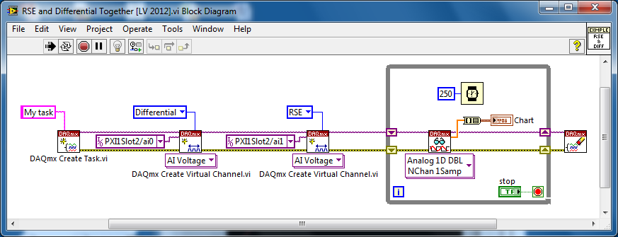
I prefer to use the 'low' level vi is therefore always curious to know if there is a way to set the configuration using the their.
It should be like this:
-
analog input external trigger 6015
Hello
I was able to configure my 6015 to accept an external trigger to start a measurement of analog input (with a # set of samples and freq). However, what I want to do is to set up so I can send a 20 kHz signal to the trigger, and whenever the trigger detects the signal, the device would take a measure of the tension of each of the two channels. He would then save this memory on board and allow me to read the data later. That's what I can't figure out how to do.
If he put in place such as I have an asynchronous callback and read data after each pulse, it takes too much time in my application. I want to get a measure for each external trigger pulse (the freq may vary higher or lower, it's why I can't put just a freq - I need to use the trigger) and these data saved in memory on the card for me to pick it up later.
Is this possible with the 6015? Another tip? If so, can you please show a few snippets of code in VB.NET or c# .NET?
Thank you
Joe
Hey Joe,
I think that your application should work fine with the 6015. I mentioned only the buffer size as previous your post said 'I want... these data stored in memory on the card to grab me afterwards,' and especially supported in NOR-DAQmx devices (including the 6015, PCI E Series, the new series X PCIe and PCI M Series) don't work that way. They have permanently transfer data in a buffer in the memory of the host throughout the acquisition PC, and they have enough buffer on board to avoid negative/overflow buffer overflow errors at their maximum supported rate
Brad
-
PXI-7831R configuration as analog inputs
Hello
I'm new on NI PXI, thought that I've worked on Labview. My PXI chassis has two modules analog output (PXI-6713 and 6733), a PXI-2501 FET multiplexer, a PXI-4070 DMM, PXI - 8464, an IEEE host module adaptation and the module a PXI-7831R reconfigurable i/o () .
I was able to properly configure my components using MAX.
The problem that I do exactly face 'takes analog input' using my PXI chassis.
With the modules above, I suppose that I can use the 7831R as analog I/o module.
But the problem is the 7831R is a FPGA module and it is not displayed in DAQmx.
So, where can I exactly find the analog 7831R pin (in the labview GUI) and how to use them in my block VI?
The next version of labview provides an interface to data acquisition even for 7831R? (my version of labview is 8.2.1).
Kindly help me to solve my problem.
You need the- module FPGA.
-
How to read the NI 9201 Module lab mode analog input signal
Hi all
IAM using the module Crio-9012 real-time controller
ND iam using NOR-9201 for entry and exit of NI9263 for
I have configures cRIO 9012 on my Pc
But how I'll take analog input using the module NOR-9201
Thank you
TC
Hello
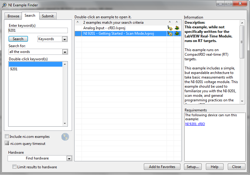
I recommend you take a look at the following examples in the example Finder LabVIEW. If you go to help--> find examples, you will see this window. Just search 9201 and you will see 2 examples:
I hope this helps!
-
Analog inputs measures with NI6229 using the DAQmx driver
Hello
I have four different analog inputs connected to ai0 to HW 6220 ai3. I read these values with a single task, all 4 channels assigned to this task. When ai0 reads 7V, I see 0.8 V ai1 too, but I expect to be measured 0V. If I just assign ai1 to the task and measure all 4 channels, then I measured 0V as expected (although ai1 contains 7V, I just don't measure it).
Another comment 'funny', is that if I change the order in which I add channels to the task, measurement errors are different.
However, when measured with a multimeter 4-channel show tensions as expected.
Given that my calling task is can not block, I call the function
DAQmxReadAnalogF64 with timeout = 0 and numSampsPerChan = 1.
Any help is appreciated.
Thank you
Kind regards
Deepa
Deepa,
Thanks for the code snippet.
When you call DAQmxReadAnalogF64 the first time and you set a value of timeout of 0, there is a chance that the acquisition is not yet initialized. This is the expected behavior and should not be a problem. If the timeout error died at the first call, you might ignore it or set a different expiration time for the first call only. In all cases, you should drop the first value and start with the second value.
Jochen
-
Synchronization of two inputs frequency meter with several analog inputs
Hi all
I'm relatively new to LabVIEW and I'm trying to collect data from multiple sources with calendar sync on the acquisition, but I can't understand. My problem is that I have two inputs frequency meter, an optical tachometer reading one pulse per revolution and a max flow meter machines with a 12000 k coefficient. I can't find a way to synchronize the calendar with my multiple analog inputs. I tried to first get the speedometer to synchronize with the analog inputs following the example linked here. (https://decibel.ni.com/content/docs/DOC-10785) So far every time I run it I get an error on the DAQmx read timeout or an error "several sample clock pulses have been detected" (see image). It seems if I slow the way to down to say 10 hz and make sampling rate ensure that the tachometer signal is more than 800-1000 rpm (13-17 Hz) before starting the VI then the program will run without error until the ROTATION speed is below this threshold, then the "sample Multiple clock pulses" error occurs. The code is attached below.
Does anyone know of a better way to synchronize the entries of frequency of the counter with analog inputs? I would like to have a VI that can display 0 RPM (and possibly 0 flow as well, but I think I need to understand the timing of a meter before I have add another, because it seems that I can't have two counters to the same task). Any help on this would be greatly appreciated.
LabVIEW version 13.0
Chassis cDAQ-9178 with NI 9401 for both counter inputs and NI 9205 for the analog inputs.
Thank you!
Richard
I know the error requires to restart the task at least (this particular error puts the material in a State that cannot be recovered from during execution of the task - I've been down this road before) but I'm surprised that you would have to delete and re-create the task altogether. And then I had to do this to workaround other questions in the past. It is awkward and should be considered a bug, if this is indeed the behavior.
Honestly, regardless of this bug, the way the material dealing with the situation of several sample clock edges makes measures of sampling frequency clocked essentially unusable for purposes of synchronization (in my opinion anyway) If you encounter a more slow than your sample clock rate. You are supposed to be "synchronization" of the measure, but it really no longer applies if you have to restart the task over and over again (if you must delete it or not).
Workarounds can get kind of creation (which isn't really a good thing). For example, you can configure a measure of implicit frequency to keep a buffer of frequencies and use a leader board task (source is the frequency signal, sample clock is the sample clock HAVE) to establish a correlation between the index of your buffer of frequency for singing HAVE sample clock.
Best regards


Maybe you are looking for
-
Port Replicator to the United Kingdom will work with US Portege R830?
A Port Replicator to speed in United Kingdom Hi (PA3838D-1PRP) will be compatible with the laptop Portege R830 American version?
-
Satellite A660-1DW or Satellite A660-17?
I ordered an A660-17F of Argos and when it arrived it is an A660 1DW. is anyone know can tell the difference of these machines? a 1DW A660 replaced A660-17 or is it a mistake by argos? are there features that I usually have if I keep the A660 1DW. I
-
someone asked saying me that someone tried to hack my computer. He wants me to follow his instructions to prevent this entrustion. He claims to be a representative of microsoft that it is the first time that anyone from microsoft called me. What is P
-
How to create a header in csv file
I m still beginner in Labview, I'm just learning it this week... I want to do a data conversion for temperature probe... I m having trouble creating a header in the csv file, can anyone help me? I am also attaching my csv file, what I wanted to do li
-
Block of sous-schemas to run in parallel
I'm still new to LabVIEW, if this question is very probably stupid. But I am a little confused by the basics. We have a hypothetical test facility. To begin a measurement of what I need: 1. turn on a couple of power supplies; (2 light up a cold room