Frequency of waveform capture
Hello
I data signals that are scrutinized every 100ms which are used for the calculations. I also display these data signals after a little massage as waveforms on operators HMI. The operator would also take the data points in the waveform and bring in excel for the purpose of data retention. Now for the purposes of the calculations, the mark of 100 ms period is good, however, the operator wishes to the wave shape have a period of 1 s. Is there a property node or the similar function block which would allow the waveform function block query data at a slower pace?
Thank you very much for the help.
I don't usually recommend screw Express, but there is a Compression of the sample one that could do the job for you.
Tags: NI Software
Similar Questions
-
Hello
We use the DMM and SMU-6363 map to test a hardware device. We will also use a PXI-2530 b switching matrix. We will use the digital multimeter to perform the measurements of voltage, DC and AC, measurements of impedance (2-wire and 4-wire), frequency and waveform acquisition. Can the PXI-4071 left be 4 wire connected (black jacks taken connected and red connected) mode and still be used to perform all other measures (including 2 impedance of the cable). This would simplify the switch connections.
Current measures use the son + and LO, but the HI and S-can remain connected. The problem you are having is if you have an active device the digital multimeter and take you a 4-wire resistance and the measurement of voltage with all 4 wires connected and then change to a current... When you do this, short-circuit you the terminals of the DUT, on that you just take the measurement of the resistance. If the terminal HAD, say, a power supply 10V, then you have just shorted out. Of course, this isn't a problem if your Instrument is a passive device, or if you change just the unused two lead whenever there is an active device of low impedance.
If you want to make voltage, current and 4-wire resistance, you need all 4 wires. If you want to do the voltage and current, you will need 3 wires, but you could connect the s + Hi and then just do the two wires. I vote running every 4 son to your DUT for maximum flexibility.
2-wire resistance is a must if you are measuring resistance above 10 MOhm. Alternatively, you can use 4-wire for all measures.
-
I do not search this Board first, but could not find an adequate response, which would be a good hardware DAQ to use to capture a signal from an audio amplifier for the measurement of noise and distortion. I'm building an amp for me so did not not a budget of manufactured goods. I was thinking about using a HP frequency generator to capture a very clean waveform and then compare this after that amplification using Labview built in functions. I have Labview 8.6 SE
Thank you!
Alan
I have not read through each link. I just found with a quick Google search and scanned them quickly.
I don't see your response as sarcastic at all. I know all too well how ugly hardware audio consumer PC. However, I think it might be quite appropriate to digitize a signal _error_, since the required loyalty is very less than that required for the measurement of the signals of interest directly. The method I mentioned has the additional advantage of being insensitive to the distortion of the signal from the source, so you can be able to use audio PC in order to predict that, as well.
Chris
-
I'm trying to identify the frequency of the sine wave signal and convert it in full. Is it easier to measure in the time domain or frequency domain? According to what is easier, should what modules and functions I use? Another engineer and I was able to go around and around to try different approaches, but just cannot find a working solution. Any help you can give is appreciated.
Bill
Bill,
I see two ways:
For higher frequency sine waves - use module of the FFT. Then the module of statistical values in mode 'Position Max' retrieves the frequency of the amplitude higher in the range.
For low-frequency sine waves, especially those where the full waveform is not in a single block, so you want to try the Pulse analysis Module. To do this, you must change the sine wave to a pulse, using the trigger module. This assumes a pure sinusoidal signal and it becomes a trigger pulse when the value rises above 0. In the simulation, this works well. I don't know how it will work with real data.
I have attached an example illustrating the techniques and results for each frequency of waveform using FFT and analysis Pulse.
-
Arduino analog read PIN frequency
Hello.
I try to convert the digital voltage (read of the analog pin on my arduino mega, an accelerometer) and perform an FFT/Spectral analysis to convert a volume from the frequency output waveform.
I'm having some trouble to accomplish this, with my release of the Arduino Pin Vi read as a double data of 16 64-real precision, which I convert a single waveform. The output of my spectral measurement through TFF (RMS) is a cluster of 1 d of 3 elements. When I have this thread to a waveform curve it changes just the values of Y (size) but often does not update the X axis at all.
Please help here is up to here a screenshot of my setup:
[IMG] http://i.imgur.com/WrzbX.PNG [line]
I've also attached the VI below.
-
The sliders are not preparing for the right place
Hello
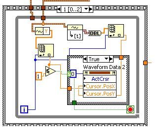
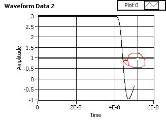
I'm the Agilent MSO7000 series oscilloscope waveform capture. I created waveformdata for one oscilloscope channel and trying to place cursors using the node property of waveform data slider and I see that he is preparing in the wrong position, as shown in the pictures below. I would like to know what is the reason behind all this.
You can see that the cursor is after the position where it should be.
Thank you
Kind regards
Sailesh
Looks like the x axis offset is not applied correctly. If you explicitly set x 0, things look better. I'll study a little more...
Here's a quick rewrite with the same functionality, but including the x 0 problem.

-
Can you 'measure' a 1 kHz, 3VDC square on a digital port of a PXI6723? I try to make sure that the connection is good so I'm sending you the (sq) waveform analog on through a differential driver/receiver circuit and back into the DIO. I test the signal to active / deactivate my FREQ. Hi > OL > salvation > OL > salvation > lo... etc...
This maybe a diff but post...
My differential driver output is high impedance when its judgment and from what I understand when the 6723 sees a high impedance there is a pull up to ~ 3 volts so he tells a Summit if I looked at the port/channel. So my question is how can I tell when the diff circuit signal is low?
MarcoMauri wrote:
crossrulz wrote:
You cannot capture a waveform with the OID. However, you could measure the freqeuncy with a counter on the same card.
Hi crossrulz,
a digital waveform capture should be possible (as shown in the example provided with Labview Cont read dig Chan-Int Clk.vi).
Am I wrong?
Kind regards
Marco
If you read the specifications of the PXI-6723, the OID are only timed software. Therefore, the values are read only when the software shows the map to enter the current value. The calendar will be not deterministic (which I think is unimportant). If you have hardware timed DIO, then a digital waveform could be captured.
-
Hi guys,.
I'm making a request:
-establish a connection socket with a server (Ip, Port),
-Send data to this server every 3 minutes
I want to connect only to the beginning and use it indefinitely,
then he;'s up to disconnect me
What kind of Exception is allows us to display whether or not the data are sent?
How will I know it's a disconnect or maybe something else, and sign in again in the catch statement?
Thank you guys
"what happens if we must also change the system and make a shipment of position in real time"
I suggest that you design your application to have two parameters
(a) the frequency at which capture you GPS locations
(b) the frequency at which put you a stop.
So if you say (a) set to 5 seconds and (b) together for 5 minutes, then you reduce the frequency of connections and send the quite a few parameters at once--good for the follow-up. If you have 30 (a) and (b), 30, then you're almost in real time.
To understand the connection on the device options and Simulator, I suggest that you only consider the following sticky thread:
http://supportforums.BlackBerry.com/Rim/Board/message?board.ID=java_dev&thread.ID=29103
-
Hello
I'm working on a project that requires two outputs digital signals at different frequencies. Frequency of the phase 1 is about 1 kHz and is modulated on and off to a pace that will change during the execution of the program. Wave 2 passes from 1 kHz to about 6 kHz while needing to be pretty accurate to the tenth of a Hertz.
Initially, I tried to manage the simultaneous output of signals at different frequencies using a single task on a single 9477 daqmx in a cdaq-9174 chassis. As far as I know, the best way to get a specific frequency in a waveform output is to set the sampling frequency up to 2 times the frequency of the wave that is generated and generate a waveform that is given to each clock cycle. This works very well when it comes to a gesture, but I was unable to get the frequency of the modulated wave (wave 1) remains constant when the frequency of wave 2 modified or vice versa.
I have a few other modules lying around (another 9477, 9403 and 9476) and I thought I would try another task running on a separate module. I find myself receive error-50103 message if I add these modules to my cdaq chassis and run one of the waveforms of a task set to run on the add-on. Is there a way to bypass this error? I guess it would cause by running two digital output on the cdaq-9174 tasks at the same time, but it seems to me that this wouldn't be a problem with an additional module.
How can I have two outputs digital signals, running at the same time, maintaining their independent frequency frequency of the clock of the other sampling rate changes. In addition, because the wave 1 is enabled and disabled at a defined frequency, I use it to set the number of samples to write when you write a range of waveforms in the module (when generating these two waveforms on the same module).
I'm sorry if the explanation was difficult to understand. I've attached an example of error 50103 lifting. This isn't really a part of my project as a whole, but it is the easiest way to reproduce the error.
Thank you
Hi awol.
I have a follow up for you. You encounter the error because the cDAQ chassis has only a timing engine of. You will not be able to perform simultaneous tasks of the call by the hardware. Please see the following knowledge base: http://digital.ni.com/public.nsf/allkb/5E0B829E50ADE1BC86257AC50062B2D2
Mike
-
Frequency domain scaling graphic of waveform
Hello world
-I m buying a random voltage signal using a sampling rate of 200 kech. / s on my device NOR and trace the signal acquired on a waveform graph (Figure 1-a). After tasting the random voltage signal my Labview VI also calculates the PSD (power spectral density) of the random signal acquired and it is plotted on a waveform graph (Figure 1B). As the sampling frequency used was set at 200 kech. / s, the maximum value on the x-axis of the curve of PSD´s waveform should be 100 kHz (Shannon´s theorem). When Labview trace PSD´s waveform graph, the maximum value appears as 1. Is it possible to scale the chart of PSD´s waveform in order to define the maximum value on the x-axis as 100 kHz?
Thank you in advance,
Best regards!
Of course, your numbers of the scale correctly and use a property of the range axis node x (your pdf says absolutely nothing about your program or your problem with it. Code would at least tell us something.)
Cameron
-
static/digital waveform output and low frequency measurement of voltage - SMU-6358
Hello
1. I have an attached VI [digital_voltage_output] who must generate a logical true or false static state in the output of the device/port0/line1 Word to say. When the VI works I click the button several times, but nothing happens to the port0/lines1.
2 such a thing [digital_voltage_waveform_output_square] if I'm trying to generate a digital waveform to pin the same with the waveform generating VI. If I connect a waveform chart to the output of the generator function VI, then the chart will show me the good waveform I want, but still nothing is written to the text file.
3. I have read the manual for the X series cards, but it remains unclear for me a little how to things of the road in LV I have a measure of the frequency measurement VI low frequency that I downloaded. It offers me the ports for the supply frequency - ctr0, 1, 2, etc. As far as I'm concerned the PFI ports are responsible for these types of actions. How can I find out the LV that I want to connect say ctr0 and pfi0? »
I use LV 8.6.
Thank you
Kriváň
Hi Kriváň,
The problem you had with the choice of a specific digital line as a physical channel, is that the control that was previously used in this example was created for a data acquisition task that uses a whole port rather than a specific line. I was able to overcome this problem by removing the control and recreate. The control now gives you the option to choose the specific digital lines e.g. port0/PXI1Slot2/$line0.
I was also able to overcome the error of-200802 you mentioned. I was able to do this in a real constant of wiring at the entrance to auto-start the VI DAQmx writing then remove the DAQmx beginning the subsequent code VI. The modified code is attached.
I hope this helps.
Best regards
Christian Hartshorne
NIUK
-
determination of the sampling rate and the frequency waveform data record
Hello
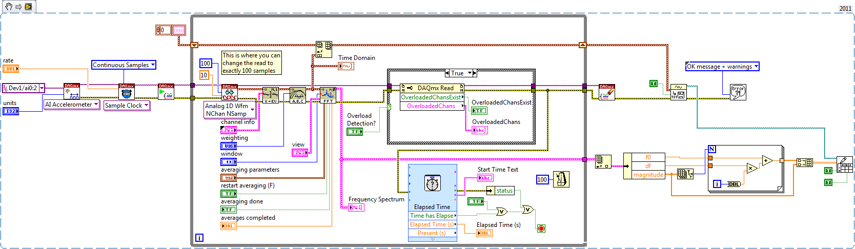
I write a simple program that collect data from a triaxial accelerometer input, convert it to a frequency spectrum, and then save the time domain and the frequency of the waveforms in an external file separated. I don't understand how to set the sampling frequency, however. On the DAQ Assistant, I updated the acquisition mode "Samples continues" and read samples is 2 k, which corresponds to the total number of data points that are collected. How can I program sampling for awhile, it 30 seconds, for example? Wouldn't be better to set up a trigger, as it will continue to collect data up to what I told it to stop?
I also want to save waveform data in a separate file that can be easily seen by other computers that have not installed Labview. I have currently the program put in place to convert a text string of the waveform of the time domain and then save it in a text file or a spreadsheet. It works fine, but I would also like to record the frequency wave, which is a different type of data. How can I do this or is there a better way?
My program is attached. Thanks for your help!
Here's how you can use the shift register to build the table, and also where you can choose to play exactly 100 samples per while the loop iteration.
Brian
-
Capture of frequency with the NI 9401 in cDAQ-9172
Hi all
I searched through all the examples and find the same results than my own code in Labview. So, I go back to my hardware to solve my problem. I use a digital tachometer that displays pulse with 2 wires (hot and ground). I connected these to the NI 9401 for 16 PINS for PFI 1 and PIN 3 on the ground. When I open the module through MAX, he reads the perfectly when hi and lo as well as count properly if it is placed in the location 5 or 6.
However, I try to use the frequency max task and the task fails to capture anything in the table. I get a time-out error, even if my tach is read correctly. I have attached my settings of the task. Thanks for any help
Your samples to read is set to 100. If all the samples of 100 are not available before the timeout is reached, you will get a time-out error. What is the frequency of the input signal? Maybe just try to read 1 sample on request first.
Best regards
-
Generate digital waveforms of high frequency
Hi all
I have some problems. Today, I am generating several digital high frequency waves with my DAQ (PCI-6251) card. The duty cycle of the waveform must be adjustable.
The required frequency is 100 kHz.
To do this, I have tried several solutions:
(1) I used counters in the acquisition of data to generate waveforms, and it worked fine. However, I have only two counters. In my application, I need to at least three waveforms with different cyclical report;
(2) I used a 'loop' and structures 'case' in labview to build the model of waveform and then feed them to the digital I/o. However, the problem with this solution is that the frequency of the wave generated cannot be high.
(3) I used a 'digital' generator in Labview to generate waveforms and then feed them to the digital I/o. In this case, the time base is from an external source (200 kHz). However, with this solution, the cycle is not adjustable.
Please give me some advice on how to make these waveforms. Your assistance is appreciated.
OK, so I may be wrong, but after mucking around for a bit, I realized that the regeneration should be automatic - in other words, if you a pattern to the right and then just leave your VI work in a while loop, you will find that the generation is continuous. Discover the correlation dig write metered in the finder for example Labview. You can leverage this as you get the cyclical report you are looking for. You can split the signal down what you write a single period consisting of a series of 0 and 1. In other words, if you want a wave of 100 kHz with a cycle of 20%, you write a pattern of digital waveforms a 1100000000 at the rate of 1 MHz. Using this technique, the resolution of the cycle will be limited by the on-board clock speed (80 MHz = 0.125%).
Let me know if this makes sense - I am unable to reproduce this on my desktop and have never had to do this before.
Cheers, Matt
-
generation of buffer desired waveform ╔chantillonnage clock and clock frequency sample resulting
Hello, I'm trying to generate a square wave on an ongoing basis for NI6221 DAQ to 2 kHz. I use the example of Cont Gen tension Wfm - Int Clk.vi, which works great for my needs. However, the synchronization frequency setting is sometimes different frequency resulting, according to the choice of the samples and the Cycles / buffer. Tracking dozn the origin of these variables, all come from the nodes property of the moment-DAQmx in Buffere waveform generation (multi) .vi, where the input and output frequencies are not the same. Now, why is it so? What is the way the rate is calculated? I guess it's related to an internal approximation of the Council divided by sweep sampling frequency, clock but how exactly?
I found some notes in the help (see figure), with a few diagrams of the oscillators according to the DAQ (M type) card, but then I'm lost.
Thank you very much
Virgilio
The AO sample clock is generated by dividing down the time base. If you select a clock frequency sample that can not be achieved by dividing the time by an integer base, the sampling clock frequency will be rounded up to the available sample rate nearest (it might be interesting to note that tasks HAVE always round the frequency rather than rounding to the nearest available).
For example, the maximum time available for AO internal base is 20 MHz. If you select a sampling frequency of 300 kHz, this wouldn't be possible (20 MHz / 66.66666...). Instead, ~298.5 kHz will be used (20 MHz / 67).
Best regards
![http://i.imgur.com/WrzbX.PNG [line]](http://i.imgur.com/WrzbX.png[/IMG])
Maybe you are looking for
-
HP Pavilion 400f: on SSD drive
Hello! I want to install an SSD in my desktop, but I don't know if it is compatible with my computer model or not. Can someone help me with this please?
-
Office Jet Pro 8600: all-in-one Officejet Pro 8600
Hello My Office Jet Pro 8600 all = 0n - one did a terible grinding noice when pulling back a page for double-sided copying. Do I nbeed something oil? Thank you Greg
-
Help! I don't know what to do... its been like that for some time my PC was overheating and I had 2 extra HD I thought that may be the problem, but they have been removed. I do not know what is Happeneing... and it drives me nuts to have my computer
-
T61 upgrade issues with T9300 cpu
Hi all I have a T61 (7659) with a T7300 cpu and m/b No. 41W1487. Can I switch to a T9300 processor, using a connected bios? I tried once, but the computer is unstable. I suspect the second-hand T9300, I received is damaged. All m/bs Merom can * unoff
-
I've been singing defrag for more space on the hard disk. Run defrag has many applications/files automatically compressed and a large part of the system does not work (for example: information system, ie8, etc.). Delete as much as I can in "Add/Remo