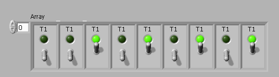
Front Panel Bank of switches and related indicators
I am the design of a test system. I would like a Bank of the individual switches on the control panel to turn the test case. I figured out how to do this. And I can do banks for the indication LEDs (pass/fail) and the field of digital test result. But, I want to tie them together. I guess I should start by using a cluster rather than a table. But how to get banks to act as a single group?
As I have so far, I have a back of switches and a Bank of indicators (of the switching status) for all just play. The indicators do not align with the switches. I'd like a match of 1 to 1 for easy operator use. When I use 'properties' to develop the Bank of the indicator, it won't take the number. It is limited internally somehow.
DH
How about an array of clusters? Easy to use and easy to watch, all lined up.
Tags: NI Software
Similar Questions
-
style of LabVIEW front panel: shades of blue and white, (Mac like?)
I was recently at the symposium on technology North of California, where I saw the head build a VI in LV2009 using what appeared to be a new style of the façade. The best I can describe it is a blue-ish/white smooth with gradients on the buttons and had a look overall Mac - like him.
Where can I get my hands on it? This is a feature of LV2009?
Hello buckidge,
In my opinion, what you are referring is Custom Control for front of VI. Here are a few links to some consequences of the custom control.
NI.com inspired Custom Control Suite
http://decibel.NI.com/content/docs/doc-4028
Theme "Military" custom control Suite
-
How to make non-visible control on the Front Panel appear at Design time?
I have a few controls on the front whose visibility is changed (on or off) at run time. The problem is that if I stop the Run time, the visibility of the control remains in the running in design mode state. So I am not able to see or find the control to make changes in design mode.
How can I make all the visible front-panel controls, or find and make it visible to a control on the front whose visibility has False?
Thank you.
It is documented in the help of LabVIEW.
Hidden front panel display
Perform the following steps to display a hidden front control or indicator. You can also hide the indicators and controls on the front panel.
- Find the terminal block schema for the object. "If you have multiple devices with the same type of data, right click on the terminals and select visible elements" Label in the context menu. Find the object with the label that corresponds to the object hidden façade.
- Right-click in the Terminal, and then select Show Control context menu if the object is a control or indicator to show if the object is an indicator.
You can also use the Visible property to display the controls and indicators by program.
You can also view all hidden front panel controls and indicators.
Path: Fundamentals-> build the façade-> how-to--> configure the objects-> display on front panel of the façade hidden object.
-
I would like to combine several orders and LEDs on the front panel in a group in a way that allows me to do the whole group Visible or not.
I tried to use a Cluster, but it has a side effect that all elements must be inside the controls or indicators, but not mixed.
Is there any graphic element, like a panel that can contain other controls and indicators on the inside and make them Visible or not as a group regardless of whether they are commands or the LEDs?
Good suggestions on how to do this?
Thank you.
The tab control is still not my favorite, appearance but it's a way fast and effective to show and hide groups of controls and indicators.
-
Hello
I have a few questions in the following way:
1. After installing the Switch Executive 3.6 (evaluation software), I have very large window for OR Soft Front Panel SWITCH to cover all 4 monitors. It is difficult to see. Do I have to uninstall 3.6 Executive switch (software evaluation)? We don't need that much. Is it safe to uninstall?
Could you give me the solutuion to configure on the previous setting the Soft Front Panel, released only to a single monitor.
2. what the Panel "pxi-2720" test should be at MAX? If I click on the test Panel, 'Switch Panel Soft' appears with the topology - '2720-independent? It looks like swich instead of test programmable resistance. Is - this Panel good criterion for pxi-2720?
3. for NI PXI 2571, I SH200LFH-4xDB50F-C cable to connect to the terminals and tested the switches. I found the NO0 (P1 pin2) - COM0 (P1 pin1) connection is not working while others work. That is reserved by something else? I have test by exchanging terminal blocks, but the result was the same.
I'm waiting for your answers.
Thank you
Insuk
Thank you!!
-
Switch Soft Front Panel, active device classified
I have a with PXI chassis modules, two switches PXI-2350. Using the Soft Front Panel switch, it seems that the names assigned to the list of active device (both 2350's in this case) are backward, what to expect. Is there a way to reassociate those names to the 2350's physics?
Thank you
Confustus,
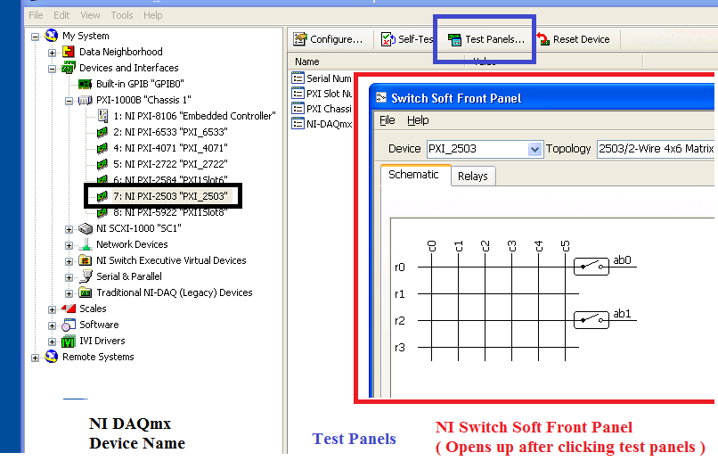
It's an interesting question that I've never seen before, your devices in a Soft Front Panel should be linked to features like labels in MAX. I was wondering, when you say "we can select using MAX, a road that connects the power supply to the digital multimeter using"Switch 1"(for example), and we can see the voltage reading show on the Soft Front Panel 4071 as planned", what you mean exactly? If you had to choose your hardware device, and then click test panels, the NI Soft Front Panel load switch. Are you saying that when you choose test panels and loading Switch Soft Front Panel of max works as expected, however the application outside opening MAX does not work?
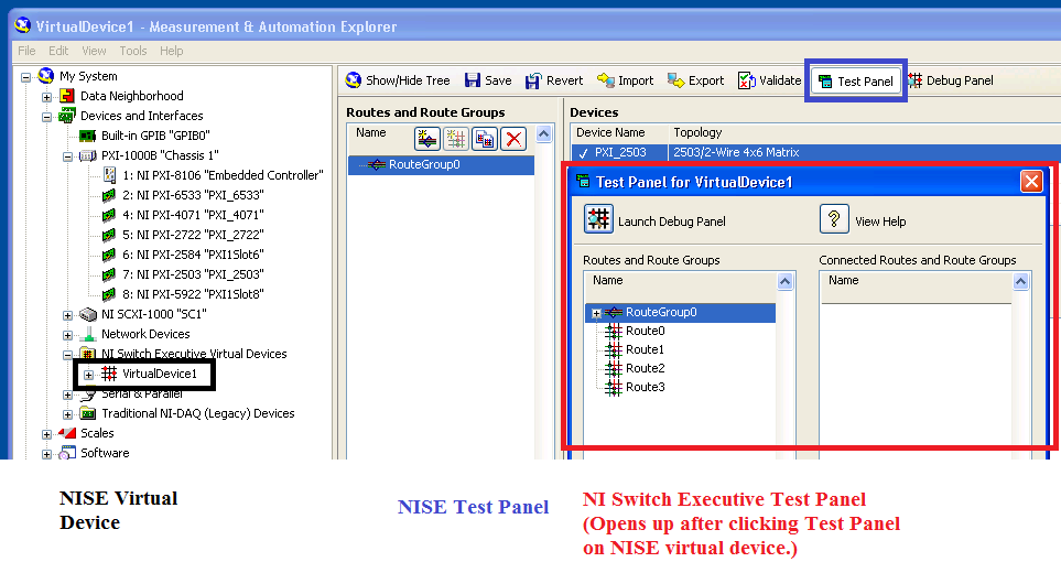
Or are you talking about the Test panels you open in NI Switch Executive? The test for NI Switch Executive panels refer on behalf of virtual device NI Switch Executive, not the DAQmx device name. If you had named the name of the NI Switch Executive virtual device in the same way, that could be part of the confusion of the problems that you see. See the images below:
NEITHER DAQmx Test selection panel that leads upward.
Test NI Switch Executive Panel allows this. If these names are similar, I can see how that might be confusing.
-
Hello
I am trying to determine what type of audio 3.5 mm plug to put into the connector on the front panel for the use of a headset to make video communications.
could be - sleeve, ring and end cap (mono audio and microphone)
or
could be - sleeve, ring, ring and tip (stereo sound and microphone)
Having read through the manuals and nothing is said on the type
to use.
Hello world
Just plugged the connector 4 poles on my headset combination for my mobile phone (cellular) and the box of pop - up asked me to select headset or microphone - no selection for both.
Looks like the right sleeve is for headphones only, and the left one is for headphones or micro - selectable by the user and not the two on a single sheet.
Everything explained by the practice - but not the paperwork in the manuals.
#5 for microphone or headset - menu popup is displayed after you insert a 3.5 mm plug to select that one but not both at the same time. (So I can't use my headset to phone)
Thank you
Son
-
How to get AC 97 Front Panel Audio and Microphone ports to work with Windows 8
I have a m7277c HP Media Center that uses the motherboard Asus P5LP-(Lithium-UL8E) and has an Audio Jack and Microphone AC 97 spec ports on the front panel. I tried to install the Codec AC 97 drivers for Windows 7 and they do not work for Windows 8. The 'High Definition Audio Codec"Windows 8 drivers only work for the Ports on the rear panel, not the Ports on the front panel.
How can I get AC 97 Front Panel Audio and Microphone ports to work with Windows 8?
Hello
Your model has not been tested for the use of Windows 8.
For this reason, HP cannot provide instructions to upgrade or Windows 8 pilots.
Therefore, it will be very difficult to provide a solution.
Thank you
-
cRIO, Webservice (REST) and front panel
Hello
I created a few simple webservice screws for greater application that runs on a cRIO. The webservice screws can be used to send simple commands to the application and give your feedback. So far, I used a LV frontpanel for interaction with the system, but for several reasons, I am looking for another way to do it.
It worked well in the development environment. After deployment webservice screw they have communicated with the application according to the needs and I am able to control the system using simple URL typed in the browser's address bar. Later, I will add static content, but for debugging, it is fine.
The thing is that now I have compiled and deployed the application, and now when I try to open the front panel I get this error message:
"VI requested is broken and cannot be read or controlled."Previously I did not use the Web OR Application Server, so I installed to use the web services. Are there conflicts between a Web application server and remote server Panel? Any suggestions on how to proceed?
I use LV 2012 and NI RIO 12.0
Best regards
Simo
Hi Simo,
If I understand correctly, you have the following configuration:
cRIO with a Web Service of LabVIEW and several Web Service screw
Some ways to debug deployed screws of LabVIEW Web Service are:
You can have the Service of the Web of LabVIEW deployed in debug and debug remote Web Service of LabVIEW desktop.
You can use a tool like factor to make it easier to apply and test your Web Service screw (similar to go to the url in the browser).
You can create LabVIEW screws of office using the Palette of HTTP Client to test the Web Service.
You mentioned the following"I have compiled and deployed the application, and now when I try to open the front panel... "
I'm a bit confused as this front panel you open. For example, do you mean that a LabVIEW project has been opened on the desktop, the Web Service of LabVIEW in the project has been deployed to the target of RT cRIO, and now, when you open the Web Service screw on the desk to look at the front panel, you get an error message?
-
Swap sides for the scales on the front panel and containers
Hi all
Very simple question here. I want to Exchange on sides of the balance on my Front Panel and specifically DSC container as a pressurized tank.
It is very easy to do with a waveform table or chart, but seems to be impossible with tanks and reservoirs.
It would be very convenient, especially for the process of DSC where I try to imitate the flow of process on the front panel and pipes could enter tanks of different sides.
Thank you!
Here is a tank with the scale on the right. Just took a few minutes with the control editor.
-
The same thing happened to me recently: the hand left panel doen't show the usual "Control Panel Home" switch and my control panel display is stuck on the classic view. Click on "Show common tasks in folder" but that doesn't change anything. Finally, I tried a restore without success point. No idea how to get back the link "control Panel Home"?
Thank you very much for your support
Alain Truchat
Split from here:
Hi, Alan.
Reset Control Panel-
Press Windows key + R
Type inetcpl.cpl regsvr32.exe/n/i
Press ok -
I'm rather new to LabVIEW, only used for about 1.5 weeks from this post, it means that I may be missing something pretty obvious due to ignorance, but is it possible to make my front to change as my changes of breakage due to the selection of the user to a certain case via the front panel?
The goal of the program is to make a simple layout for a user who uses the digital multimeter that the proposed code is designed for and I don't want tons of digital controllers and such clutter the screen that do not work with the function of the user uses to measure with.
Thanks in advance.

Yes.
Two ways: 1. use a tab control.
2. use of property nodes (Visible property).
The tab control is a bit easier on the block diagram, but if some controls should appear in many cases it is difficult to do. Property nodes take more space on the diagram but allows you the versatility to do almost everything you want.
Read the help files and look at a few examples.
Lynn
-
OfficeJet 6500 has 710n all LEDs on the front panel are flashing and nothing works. Any suggestions?
As indicated in the subject line, all of the lights on the front panel are flashing and nothing works. Will not communicate via cable or wireless. Green light is visible on the power supply. Suggestions?
It seems that the printer needs to be reset.
Cut the power to the printer for a minute. Reconnect the power to the printer and turn it on.
Does have an effect?
-
Hello
Can anyone help. I am currently doing a project for College. Basically, my plan is to use labview to control a temp of DP watlow controller to turn on a heater off the coast. I want only basic as set functions of preforms and read the temperature and possibly graph temperature. I will also put in place a regular thermostat and relay to switch on and switch off the device and use it again the PDD to monitor and graph of this temperature. My project is basically to graphically display the benefits of PID regulation.
Now, here's my problem. I'm pretty much a perfect beginner when it comes of labview and programming. I downloaded Labview instrument for the DP controller drivers, but I have no idea how to use. I got the connection from my laptop to the watlow via internet but I have no idea on how to get on the cat of my watlow labview. When I opened the drivers of instruments is just a load of Subvi and I don't know what to wire to the place where, or what to use to get a simple button on the front panel by increasing or decreasing the set temperature.
Any help would be appreciated to massivly
Thank you
Hi, Declan,
Yes, they are the right drivers. I assume you are using LabView 8.0 or later version. Just to help you get started, here is the link which explains the fundamental band of instrument drivers.
Internally, the VI in an instrument is organized into six categories.
(1) ' initialize VI"establishes the communication with the instrument and is the first driver of the instrument calls VI
(2) "set screws" are software routines that configure the instrument to perform specific operations. After calling these VI instrument is ready to take the step.
(3) ' command screw action/Status' the instrument to perform an action or to get the current status of the instrument or pending operations
4 "data" screws from the instrument of transfer or date
(5) "utility" VI run various auxiliary operations, such as reset and self-test
(6) ' close' close VI ends the connection of the instrument software. It's the last pilot instrument called VI.
There is a help function (?) the top tablet of your block diagram window, if you click on that and put your cursor on the VI it tells you the function and what it takes to be connected in VI. This should be enough to get you started.
There are also a few examples to the finder OR example-> entry material / output-> instrumentation drivers-> labview plug-and-play (if you can't find them please install the instruments from hereaggilent) who should give you an idea of how works driver programming and instruments. This should be enough to get you started. I'll try to find you some examples that are related to your project.
Also if you are in the United Kingdom and needs help with learning LabView programming you can call 01635 523545, and they can organize courses for you.
Best regards
-
PNG resize problem on front Panel (not stripped)
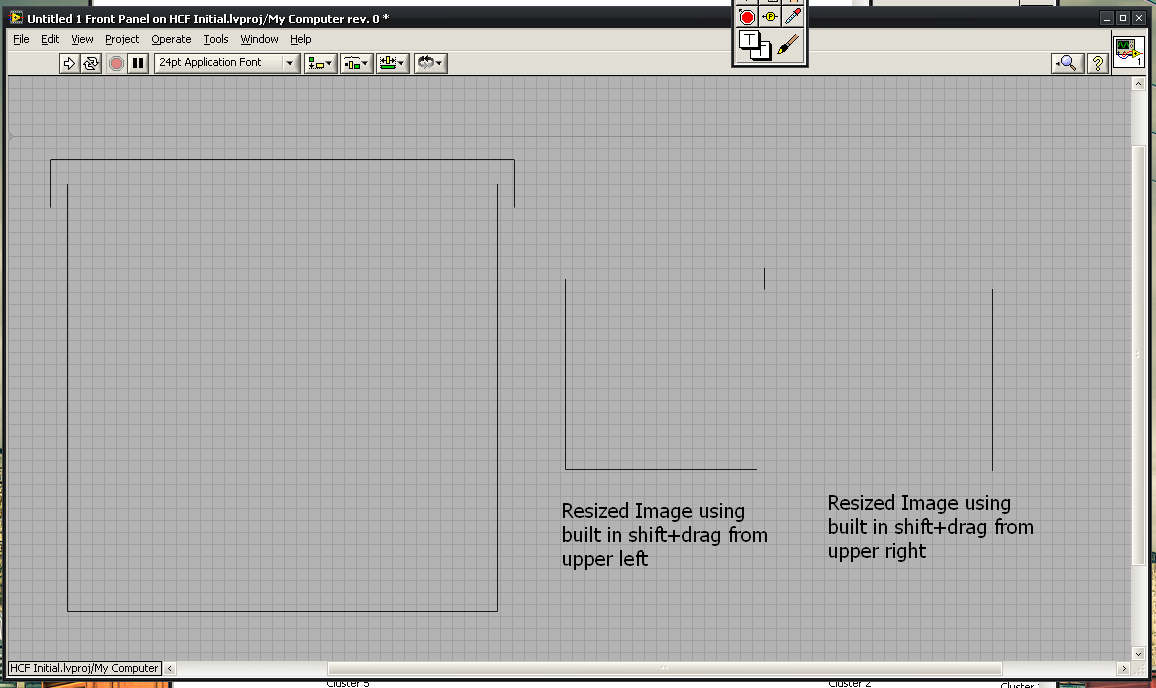
I'm having a problem trying to develop custom controls and expand my GUI beyond the default options Labview. I'm using a Visio flowchart to illustrate an industrial process. I encountered a problem trying to add items such as indicators of tanks to the façade. To do this, I'm importing Visio images, in photoshop and then saving them as png to maintain transparency. The problem I have is that when I drop this file .png on the front panel and resize, Labview seems to be falling pixels and cut the edges of my image. This seems to happen on which corner I resize the base.
Example:
Sample PNG bumped against a new front and then resized using the building in the container box.
I have the same problems with the .gif files. I have reviewed the various .png and .gif export options, and I don't see anything that I'm missing. I don't have a problem with JPEG files, so it must be something related to transparency. Is this a known problem or there at - it a labview option, I'm missing? I am currenlty using Labview 2010 SP1.
Given that I'm still in phase of my development of gui layout, I don't know the exact dimensions of all my items and I was hoping I'd be able to resize it as I'm going to and not to be completely locked in at custom controls. Any idea would be appreciated. I searched the forums, but all the questions that I could find were mostly programmatically resizing problems.
One option, you can try exporting the EMF or WMF image. LV should be able to import that, and because it is a vector format, in my opinion, it should also resize correctly.
Another alternative is to draw in BT itself, either decorations or control of image to draw programmatically (although you should be aware that this option can have performance issues).
Maybe you are looking for
-
Function to return all the variables in the expression list on 50 G?
What is the function on the 50G will return all variables used in algebraic exoression list? Example entry: (x + y) ^ z / x output: {x y z}
-
Converts a hexadecimal string to ASCII by VBAI
Good day, experts, OR the I would like to ask for help on the stage of the VBAI calculator. Is there a way I could convert a hexadecimal string to ASCII character? For example 25 (Hex) to %(ASCII) or, if not in the calculator to other methods? I'll h
-
My computer didn't work since I installed SP2 for Vista
After installing service pack 2 for Vista my computer restarted itself and everything that appears is the screen with the following message Windows Boot Manager: Windows could not start. A recent hardware or software change might be the cause. To sol
-
Headset Bluetooth vista crashes
I bought Bueant z9 bluetooth headset for use with Skype. Unfortunately, it breaks down vista and returns a code to STOP #8. Someone knows how to fix this?I have Dell 6400 with a BT355 module.Previous research suggests that it is a bad driver but how
-
Optical mouse NSB worked later Unknow device
Well I bought my mouse about two weeks ago and it works but now all of a sudden I was playing a game when he stops working, so I tried to connect it to my mother commputer but same cana nyone help me it's optical mouse NSB is the company that makes i