Full scale PXI - 6254 DAQmx Analog Input
Hello
I use PXI - 6254 Board to read the analog inputs. Configured channels using DAQmx create Channel.vi with sub parameters.
In the configuration: CSR
Min: 0
Max: 10
Units: Volt
I read the channel using DAQmx Read U16 2D with the sample of 1. I expected below the values.
data of 0 v = 0
10 volts = 65535 data
but it gives 10 volts = 31544 data. Please let me know why.
If I set up the channels with the settings below:
In the configuration: CSR
Min:-10
Max: 10
Units: Volt
He always reads the same values (data 0 v = 0, 10 volts = 31544).
Please let me know, how I can get 10 volts = 65535
Thank you
Hi LVTestek,
The PXI-6254 is not an interval 0 to 10 V input V. The specification of 625 x OR lists the available input ranges:
Entry level of ± 10 V, ± 5 V, ±2 V, ± 1 V, ±0, 5 V, ±0, 2 V, ±0, 1 V...
When you set Min = Max 0 = 10, DAQmx chooses the smaller input range that allows to measure signals between 0 V and 10 V without clipping. On the PXI-6254, the smaller input range that meets this criterion is the range of ± 10 V, where - 10 V corresponds to-32768 0 V corresponds to 0 and 10 V corresponds to 32767.
However, there is an additional complication: ranges entry on M Series devices are slightly wider to accommodate the software calibration. Otherwise, gain of a device could reduce the scope of actual entry, and offset error would move the ends of the effective input range. If the [-10 V...] 10 v] range on your PXI-6254 could be more like [-10.3 V...] 10.4 V]. 10 V is actually to 31544, rather than 32767. On another PXI-6254, 10 V could correspond to a different value of gross / scaleless and 31539 31552.
Another side effect of calibration of the software, is that the data returned by the flavours 'raw' and 'no' to the VI DAQmx Read are benchmarked. The KB explains further: is raw data DAQmx calibrated or chipped?
If you can modify your application to use one of the flavors "on the scale" (F64) VI DAQmx read, which should save a lot of effort. If not, could you explain why your program requires readings without scales/bullies? The right approach depends on the requirements. For example, if you want to save the data in a file and you need to reduce the file size by using raw data / scaleless, configuration DAQmx to save data directly a TDMS file can meet your needs. If you update an older application to work with DAQmx and M Series, a different approach may be more appropriate.
Brad
Tags: NI Hardware
Similar Questions
-
6036E PCMCIA + DAQmx (analog input) seems to only read in blocks of 512 samples of data
Hello people,
I ask this question before I post any code or software versions etc to see if there is a simple answer.
I use a PCMCIA card 6036E to read an analog input channel (DAQmx... i. e create task, create the channel, set the altimeter (continuous samples), task, read in a programmed software loop while (ASAP)). No matter how I put my sample rate, number of samples per channel (i.e. size of buffer), or the number of samples to be read, it looks like I can get multiples of 512 samples.
Here are some samples freq (Fs), the 'number of samples to read' asked and the actual number of samples read:
FS numberOfSamplesRequested numberOfSamplesActuallyRead
200Hz 20 512
1000 1024 5000Hz
2000 2048 5000Hz
QUESTIONS RELATING TO THE:
1 is this 'normal' behavior a 6036E PCMCIA card?
2. in the case, has anyone who may have seen this problem determined the cause and how to "fix it"?
Best regards
Chris
chassan wrote:
Hello people,
QUESTIONS RELATING TO THE:
1 is this 'normal' behavior a 6036E PCMCIA card?
Sort of.
2. in the case, has anyone who may have seen this problem determined the cause and how to "fix it"?
Best regards
Chris
Systems PCI DMA is used to transfer
the data, daqmx and receive messages when the number of samples are
acquis. Now on PC-card that does not work and the data is transferred
When the edge buffer is full (after 2 k of data) to 2 channels
10 Hz, it can take some time.
There is a work-around, there is a property where you can set the transfer mechanism (I have not daqmx on this PC), or the daqmx polling mechanism. Try these.Found a document KB.
Tone
-
DAQmx: Analog input directly to the analog output at the hardware level
Hi all
I searched for a while, but I couldn't find any suitable implementation for what I'm trying to do. A person where I work introduced me to an interesting challenge. Is there a way to set up a DAQmx task (or set up otherwise an MIO Board) to route an entry directly to an output to the analog analog hardware level? You may be thinking, "why the hell would you do? To reduce the electrical complexity, a colleague would like to concurrently read an entry while 'reproduction' of its signal on analog analog output. I know that I can easily accomplish this while the buffering by the PC, but they are interested in ensuring that the output signal is also similar to the input at the level of KHz signal, by introducing a minimal difference in phase (shift buffering of the PC).
For the record, we have for most old maps of the E series here like the PCI-6070E (PCI-MIO-16-1). I was first asked if it could be done through SCXI, but I figured I would start by asking about the MIO tips.
This looks like a long shot, and I've never heard of someone at - he never did this, but I thought I'd ask to be sure!
Thank you
Jim
Hi Jim,.
With the help of our driver is not a means of generating data directly from the FIFO of AI, it must first pass through the software. You can try the following code to the output of one of THE duplicate on the AO line to see what kind of delay you can imagine. It is similar to your original with a few adjustments code:
Use delayed output Version of avian influenza in DAQmx AO
It seems you need to do, you might consider instead the search by using a voltage follower to isolate the Vout wine.
Best regards
John
-
The use of more than 16 analog inputs of a module?
Happy new year to everyone.
The analog input module OR-DAQmx can only support up to 16 channels. Now serveral DAQ cards provide more than 16 channels, including PCI - 6259M offer 32 entered analog.
So, how do dasylab (Ver 11) support more than 16 channels in a NOR-DAQmx analog input module?
Hello srm2003,
(1) build your task NI MAX for your camera - 6259 - 01.png.
(2) DASYLab: Take a first OR-DAQmx analog input module, choose the task of MAX and configure the channels 0... device 0 15... module 15 - photo 6259 - 02.png.
(3) DASYLab: Take a second NOR-DAQmx analog input module, choose the task of MAX and configure channels 16... device 31 0... module 15 - photo 6259 - 03.png.
(4) now you have 2 HAVE modules to manage channels 0... 15 (first) and 16... 31 (second).
Best regards
MHa -
PXI-6071e offset drift on the analog inputs
Hi, I have three cards PXI-6071E, sitting in a PXI-1042 chassis that is controlled by a computer with windows XP. The 6071Es are connected to the SCB-100 break out boxes that are wired to a pannel of BNC female Panel Mount on twisted pair.
I noticed that all of my analog inputs will drift around-10 V to + 10 V if they are not connected to what whether forcing them to a certain tension. This has always happened. We also see a bit of crosstalk between channels. For example if I open a panel of test in the measurement and automation Explorer I can watch the voltage read on the drift tickets through their full range, and alteration of the signals on nearby channels will appear on the channel, I am able.
Is this just standard behavior and to predict? Is there something more I could do to minimize this drift and crosstalk? I am trying to reduce noise in my system so I figure optimize my DAQ could not hurt.
Thank you
With nothing plugged into the catch to high impedance, drifting you see is quite normal. The front end of the circuitry builds up a charge, crosstalk is proabably due to the multiplexer input (did not check but I think that the 6071 has a) transferring the load to the other channels when they are analyzed.
Search the Forum of ghosting, you will find related discussions.
-AK2DM
-
Analog input problems using PXI-6232
I tried to solve this problem for a while now without a bit of luck. Solution suggestions are welcome.
I use a PXI-6232 with LabView 8.5.1 to accept signals analog several of my sensors. Based on the signals as a PWM signal is generated and the output using PXI-6713.
Some of the analog input signals have spikes in them, which occur at all times during the tests. I watched the same signals on an oscilloscope - without crampons. I change my hardware configuration, and the spikes still occur in the same places. It seems that the program makes some resets resulting in measurement errors.
I have attached the VI and a JPEG of measured inputs.
Thanks in advance
Concerning
Vadim
I was first confused of your time scale
 but it seems that these spices occur every 20ms (not s) what to a line 50 Hz noise due to switching power converters (or a diode without compensation bridges
  )
)Another clue was the measure of the scope. While using the application scope, you opened a groundloop so the spikes because of the dI/DT through the groundloop are another way to get around.
So I'm pretty sure this isn't data acquisition (in this case) this is your configuration.
Provide a cleaning (low R AND L low) path of power (keep them close and twist slightly if possible), add a filter to down the dI/dt, identify the ground loops. (Use your scope with a little as a sensor at the entrance to reel and catch magnetic fields can open eyes)
THEN to clean the last ears (on the acquisition of data) to get the last ppm use selfs
-
PXI-7831R configuration as analog inputs
Hello
I'm new on NI PXI, thought that I've worked on Labview. My PXI chassis has two modules analog output (PXI-6713 and 6733), a PXI-2501 FET multiplexer, a PXI-4070 DMM, PXI - 8464, an IEEE host module adaptation and the module a PXI-7831R reconfigurable i/o () .
I was able to properly configure my components using MAX.
The problem that I do exactly face 'takes analog input' using my PXI chassis.
With the modules above, I suppose that I can use the 7831R as analog I/o module.
But the problem is the 7831R is a FPGA module and it is not displayed in DAQmx.
So, where can I exactly find the analog 7831R pin (in the labview GUI) and how to use them in my block VI?
The next version of labview provides an interface to data acquisition even for 7831R? (my version of labview is 8.2.1).
Kindly help me to solve my problem.
You need the- module FPGA.
-
Frequency measurement of analog input using DAQmx C APIs on SMU-6341 map
Hello
I use Linux DAQmx and attempt to measure the frequency of analog input using the map DAQ SMU-6341.
There is an ANSI-C frequency measurement example:
/ usr/local/natinst/nidaqmx/examples/ansi_c/Analog_In/Measure_Frequency/Cont_Freq-Int_Clk-SCXI1126
However, the call to DAQmxCreateAIFreqVoltageChan results in the following error:
DAQmx error: selected physical channel does not support the type of measure required by the virtual channel you create.
Create a channel to a type of measure that is supported by the physical channel, or select a physical channel that supports the type of measure.
Property: DAQmx_AI_MeasType
Required value: DAQmx_Val_Freq_Voltage
Possible values: DAQmx_Val_Current, DAQmx_Val_Resistance, DAQmx_Val_Strain_Gage, DAQmx_Val_Temp_BuiltInSensor, DAQmx_Val_Temp_RTD, DAQmx_Val_Temp_Thrmstr, DAQmx_Val_Temp_TC, DAQmx_Val_Voltage, DAQmx_Val_Voltage_CustomWithExcitationTask name: _unnamedTask<0>
State code:-200431
DAQmx does support the function of the frequency on the map 6341, or should we use examples of voltage and calculate the frequency manually?
Frequency of HAVE it is a type of channel that has been supported only on the SCXI module name of the example.
You will need to use a voltage input channel and calculate the frequency manually for your device.
-
PXI-6070E, how can I configure which are two analog input pins?
Hello
I'm reading 3 analog signals using PXI or 6070E simultaneously. I'm looking for on what axes correspond to what analog inputs? It's the same thing all the time, or should I set up?
For example, currently, the pines 68 and 34 are the + and - of the AI0 channel. But I can't find the rest.
Thank you.
How you are looking for the list of the pins? Look in the manual or in MAX, right-click on the device and select 'device pinouts. Ai0 is 68, ai1 is 33, ai2 is 65. The pins do not change. What changes is ending the pins to use if differential or single acquisition. For example, if you purchase a differential signal with ai0, you use pins 68 (ai0) and 34 (ai8).
-
Medium-sized dynamic data analog input read DAQmx read
Hi, I'm new to labview. Is there an easy way to index using the dynamics of data returned by a readout DAQmx x samples to calculate a moving average? My thought was to read the analog input for X samples pump with the data in another loop through the data, but I can't quite understand how index using the returned data set to extract the measurement value double returned for each sample.
Any ideas on that?
Thank you...
If you get a type of waveform data, why did you ask on dynamic data? No, of course not would you use the conversion of dynamic data on a waveform.
If you want only one channel, then your DAQmx Read could be changed to 1Chan NSamp. If your channel list only has one channel, you will get a table 1 d with a single element that can be indexed. To get the average of a waveform use the statistical function with the waveform. You use the average Point by Point, and not the average function that has a table for an entry.
Make sure you always have context-sensitive help on. You can avoid many of these rookie mistakes simple.
-
How to read the analog inputs of one Board of R for (PXI-7851R) series
You can guide me please with the steps for reading of the analog inputs of a series a. card I use as the target fpga PXI-7851R.
Have you looked at the examples provided with LabVIEW? There are examples showing how to read the analog inputs.
-
Analog inputs measures with NI6229 using the DAQmx driver
Hello
I have four different analog inputs connected to ai0 to HW 6220 ai3. I read these values with a single task, all 4 channels assigned to this task. When ai0 reads 7V, I see 0.8 V ai1 too, but I expect to be measured 0V. If I just assign ai1 to the task and measure all 4 channels, then I measured 0V as expected (although ai1 contains 7V, I just don't measure it).
Another comment 'funny', is that if I change the order in which I add channels to the task, measurement errors are different.
However, when measured with a multimeter 4-channel show tensions as expected.
Given that my calling task is can not block, I call the function
DAQmxReadAnalogF64 with timeout = 0 and numSampsPerChan = 1.
Any help is appreciated.
Thank you
Kind regards
Deepa
Deepa,
Thanks for the code snippet.
When you call DAQmxReadAnalogF64 the first time and you set a value of timeout of 0, there is a chance that the acquisition is not yet initialized. This is the expected behavior and should not be a problem. If the timeout error died at the first call, you might ignore it or set a different expiration time for the first call only. In all cases, you should drop the first value and start with the second value.
Jochen
-
Hallo,
I use the following system:
- OR PXI-1044 with controller NI PXI-8109
- OR PXI-2564 switch module to turn on the monitor of my test device
- Data acquisition multifunction NI PXI-6259 to measure the signal that responded to the questionnaire jump
The two cards are the same - PXI trigger bus. For both, PXI-2564 and PXI-6259 I use DAQmx to set the reading and writing of the channels.
Now, I want to measure the time between the digital output, my unit turns and the analog input, which measures the response of my system.
I can't do work by myself, please help me!
I thank Ludwig.
Hi Ludwig,.
If you can't give us any VI we have difficulties with to help you.
Because I Donat knowledge how your program is mounted it is not easy to know where you should enter signals.
Here's a question similar to yours:
http://forums.NI.com/T5/LabVIEW/best-way-to-measure-time/TD-p/178704
and 2 external links:
http://www.ehow.com/how_8698983_measure-time-LabVIEW.html
http://objectmix.com/LabVIEW/385152-how-can-i-use-LabVIEW-measure-time-between-analog-pulses.html
-
Continually acquire analog input, internal clock, break, Multiple device
I have a PXI chassis with 6 cards SMU-6363. I want to acquire data on the channels of each SMU-6363 map continuous AI, using the internal clock for timing. I need to use a trigger to pause reading of a DI on one of the cards SMU-6363 for a break and to reactivate the acquisition. I came across this example: https://decibel.ni.com/content/docs/DOC-12256/ , but keep getting error-201019 DAQmx start task "trigger break is not supported in a task to more devices. To configure the start of break in a multi-device configuration, you must use no more than one device per task and route manually clock in demand signals. »
The problem is that the configuration of I is made during execution by the operator. Sometimes they want to acquire data on one HERE through all 6 cards SMU-6363, sometimes they want to acquire data on each channel of AI through all 6 cards SMU-6363. What makes the task definition until manually route clock signals between devices for each rather difficult task.
Is there a simpler way to solve this problem?
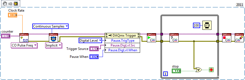
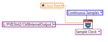
Set a task to output counter - something like this:
Next, configure your task of analog input to use the sample clock output of the meter:
Best regards
-
How can I use my PXI-6115 meter analog signal trigger to generate pulses of frequency
I work on a PXI-6115 DAQ card and want to using the analog signal to trigger the counter it's generating frequency pulses. The manual says the analog trigger is supported, but I can't use an analog signal to trigger the start of work, in the test, I use the counter 0 to generate pulses and use the signal input port analog trigger PFI 0, can someone tell me what it is? My test VI. & error message appears in the attachment.
Best regards
If you read the error you can see digital triggers are the available trigger only when you use the output of the counter.
You can work around this by setting up a dummy analog input task which will trigger an internal digital triggering when he sees the right analog trigger.
See this thread for more details:
Maybe you are looking for
-
How do you prevent ads from appearing when I'm on Firefox?
Ads appear whenever I am on a Web page and are distracting. They usually appear on the right side of my computer screen. How can I avoid them? Thank you.
-
After restoring characteristic running firefox 'research' does not work anymore
'Search' in the options also is no longer works
-
My iMac update installed iTunes 14.2.3 x 4
4 x the installation of the backup version of iTunes 14.2.3. Is this just another bug to wait? Should I do something to prevent this loss of time?
-
Canon pixma PIXMA MX459 and mx452 the same?
Canon pixma PIXMA MX459 and mx452 the same?
-
No sound audio of youtube videos.
I already use windows update, check the drivers, sound card and speakers.