Gauge
How to use two needles in a digital gauge...? I can control the two needles at a time. ??
Thanks in advance...
Yes when you right-click on the gauge, you will get an option called Add needle and in the comic book your control will pass a cluster unbundle that and take parameters. I highly recommend you go through the tutorials of basic in LabVIEW. Better cross materials and play with LabVIEW.
Tags: NI Software
Similar Questions
-
gauge the battery to the boot screen and battery on report menu conflicting Details about the level of the battery. The gauge from the battery to the Starter incorrectly displays the low battery level that prevent the start of the battery. This happens on macbook pro retina 13 inches
When I try to startup macbook pro retina in battery mode, it will fail to start showing low battery level and an indicator to recharge the battery. It does not start on battery. When I then connect via the power cable at startup (and check the battery level), monitor of battery in the menu bar indicates that the battery is charged to the top.
It gets really frustrating and remove my ability to use the macbook pro retina as a truly portable device...
Appreciate any help on this
Have you tried resetting the SMC? Reset the management system (SCM) controller on your Mac - Apple Support
-
Gauge Power Manager: An error occurred when loading Resource Dll
Just installed windows 10. A dialog window opens immediately after the opening session, saying: gauge of Power Manager: "an error occurred loading resource dll. Power Manager pilot was updated using the System Update and Windows Update. Windows seems to work very well after closing the dialog box.
Event log:
The failing application name: rundll32.exe_PWMTR64V.dll, version: 10.0.10240.16384, time stamp: 0x559f39d6
The failed module name: IMM32.dll_unloaded, version: 10.0.10240.16384, time stamp: 0x559f3b64
Exception code: 0xc000041d
Offset: 0x0000000000004c70
ID of the process failed: 0x17bc
Start time of application vulnerabilities: 0x01d0cc1e64ae9c62
The failing application path: C:\WINDOWS\system32\rundll32.exe
Path of the failing module: IMM32.dll
Report ID: dc5d2634-1815-4621-9b48-fdd9d21c8ba8
Faulting full name of the package:
ID of the failed package-parent application:
Solved. The error comes from the task by Lenovo power parameters. By disabling the task in the Task Scheduler, the error disappeared.
This does not affect the function of parameters of Lenovo, just put a little slow to load power information.
-
What is the small black gauge at the top left of the desktop?
 What is the small black gauge at the top left of the desktop? I just got my 10 Omni and put in place today. The screen (office) has this stupid black bar (gauge) on what reads 100. I can't move, close or to understand what it does. Can someone help?
Thank you... sometimes we old guys are a little slower to learn new things
FayetteTerry
I spotted your request when it was 1st posted, but I have not experienced the 'phenomenon' myself so I waited for someone who had to post a fix - might save you a few troubleshooting steps...
If you have already found a solution, update your original post could help direct others to this solution in the future. On the other hand, we can proceed to try a few things to narrow down what is causing this burning "black beast" on the screen of your Tablet:
Right of sending, no matter the cause - just shut down and then restart your tablet can correct the problem. If the bar persists after that, you can check via the Task Manager to identify a suspect probably under Startup items. Your description suggests a battery gadget or an application that uses the built-in microphone shows the sensitivity of the MIC's setting - possibly Skype or other software 'social media '.
Please update this thread with your status current re. This issue...
-
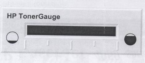
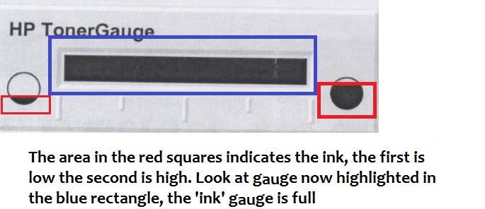
When I tried checking remaining toner, what follows has shown, that tells me nothing?
Help.
Thank you
oldtrout - arsaidh-Brack
GUM BI LEAT SI\TH
Today is perhaps the happiest day of your life and
succeeding every day be even better.
May I always be the kind of person
My dog thinks I'mHi oldtrout,.
Although I don't know what printer you have, or where you find this gauge of toner, I suspect the image that the toner is full.
I hope that answers your request.
-
Negative results with strain gauges
When I run my VI the results are always negative. I use the NI9237 with the NI9945. I wired my installation as one quarter bridge. There are three wires from the strain gauge. I went on the wires and I think it's okay / characteristics of NEITHER. Is there something in the MAX that I should be looking. Not sure why the values are negative.
Thank you
Harry Stone
Hi Harry,.
There are a few things I want to clarify:
-Traction deformation is positive and compression deformation is negative, what is described a high level in the tutorial below.
Strain with gauges
http://zone.NI.com/DevZone/CDA/tut/p/ID/3642As strain compression is negative, you would see negative within MAX results if your strain gauge knows any compression. Please keep in mind that a shift can be associated with each transducer, that's why some sensors use a calibration certificate. It is produced by the manufacturer and is provided with the sensor as is the specific sensor. The sensor goes through a testing process to determine its actual response compared to the ideal. In this case, a scale of table can be created to include these values.
How to do a custom able scale & Automation Explorer (MAX)?
http://digital.NI.com/public.nsf/allkb/3F6558112FD2C776862575B5004F7F87?OpenDocumentNot all manufacturers of sensors provide a calibration certificate. Or you can create your own table by placing known quantities of pressure, force, etc. on the sensor and map it to the corresponding voltage, or you can create a linear scale in MAX adjusting the intercept (b) the value necessary to remove any compensation.
You use the NI 9237 that compensated supports deletion. A null offset is executed with the sensor fixed without load placed on the sensor. Actually, a measurement of voltage is taken and this value is subtracted off the coast of each subsequent measure therefore removing the start offset. This takes up space you creating a linear scale and in doing so manually.
The two links below show how to use a custom scale created in MAX in LabVIEW, as well as coding the custom in LabVIEW scale to remove the dependency of MAX.
Acquisition of DAQmx with custom scale
http://decibel.NI.com/content/docs/doc-3706Create a linear scale customized for each channel AI in LabVIEW using DAQmx
http://decibel.NI.com/content/docs/doc-11136I recommend using a task sequence. Input parameters for the information about your strain gauge needed to perform the conversions of strain. There is an example of a measure of deformation in the example Finder LabVIEW (* open LabVIEW * help > find examples) designed specifically for the NI9237 that incorporate deleting the offset and shunt calibration devices. If you do not have external wires connected for calibrating shunt such as cited in this document , you will receive an error. Here is an explanation from the NI-DAQmx help Shunt calibration (start > all programs > National Instruments > NOR-DAQ > NOR-DAQmx help) to help better explain this feature.
Shunt calibration (adjustment of Gain)
You can check the output of a measurement system based on a bridge by comparing the measured output bridge with a calculated value if the physical load on the sensor is known. NOR-DAQmx can then use the difference (if any) between calculated and measured values as a factor of adjustment of gain for each measure. You can simulate the application of a load at the bridge by connecting a significant resistance in parallel with the bridge. This resistance, known as a shunt resistance, compensates for the voltage from zero of the bridge. Because the value of the shunt resistance is known, you can calculate the physical load corresponding to the voltage drop of the resistance.Use the Shunt calibration perform the Assistant DAQ or DAQmx VI/function to perform a calibration shunt, which defines the the gain setting for a virtual channel. NOR-DAQmx then uses this adjustment of gain when you descale readings from the bridge. Some National Instruments products are internal resistance.
This may seem like information overload, but I wanted to provide you with a detailed explanation of your understanding, in addition to immediate responses. As a logbook, I recommend that you use the 9237 strain example and use the removal compensation. Negative values are expected for compression and positive for blood. The handy Guide below gives an excellent overview of the strain gauges, which also includes a video.
Measurements with strain strain gauges: practical Guide
http://zone.NI.com/DevZone/CDA/tut/p/ID/7130Hope this helps!
-
With the help of the strain gauge convert read vi
I'm having trouble with the wiring of the strain gauge convert reading vi. Are there examples of this vi showing how to connect?
Thank you
HS
Have you checked the help file to this topic?
http://zone.NI.com/reference/en-XX/help/371361G-01/lvinstio/conv_strain_read/
There seems to be some examples of stock to use, but the help files for these screws can be VERY useful.
-
Measure the voltage of strain gauge
I have connected my 9237 to a 9945. I use a 350 ohm strain gauge. I have the voltage set to 2, 5V Max is there a way to measure physically to be sure that it is 2.5V? Also, in my vi I use a DAQmx create function of the channel. I want to add another channel for this but can't see how to do it.
Thank you
HS
Hi, Harry, it's Paul with engineering Applications to the OR.
My first question is why you are wanting to physically measure the voltage?
If you are wondering how that tension may vary, it is limited by the maximum capacity of 150mW of your device, as explained here: http://digital.ni.com/public.nsf/allkb/7CBC67482CC9FB318625758C0048FF73?OpenDocument
If you want to continue to measure externally, you have a few options. You can use another DAQ hardware to measure the voltage, or you can use another external device, like a digital multimeter.
If you want to see in the excitement that is actually supplied LabVIEW code, you can use the node property DAQmx 'Value of real excitement'.
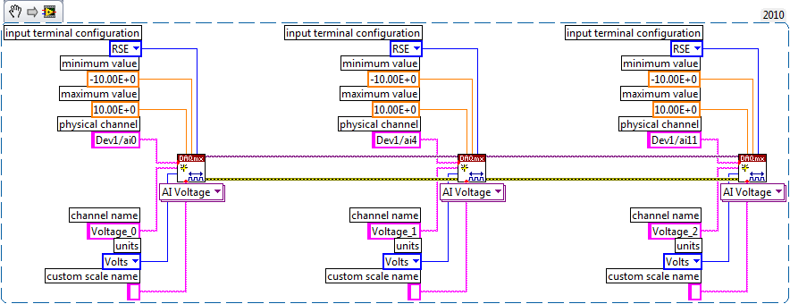
As far as playback of multiple channels, theres two ways you can go about it. If your channels are sequential and all have the same settings, then you can change your name of the physical channel to something like 'Dev1/ai0' to ' Dev1 / ai0:3: to specify the first 4 channels.» Alternatively, if you wanted to select non sequential channels, you can chain create channel set tasks, as long as they are of the same type of task (AI voltage, etc.) and the same device, as shown below.
Let us know if you have any other questions.
Kind regards
Paul
-
custom indicator gauge needles
Someone at - it something for the manufacture of different types of needles for an indicator on the dipstick? For example, I want to show an instantaneous value with standard needle as well as an average value or threshold with a line or a triangle of external pointing inward. I thought using markers of scale arbitrary and covering of the tick mark, but can't seem to do it either. I can do those two things on an indicator of the slide, but can't seem to do the equivalent on a gauge. I know that I could probably do it with an image, but it seems a lot of work.
LV 2011 defines two different hands:
Customize control, editing, import the image of the needle
-
To win a set of multiple strain gauges
Hello
We are using several gauges of constraint and "Calibration of Shunt DAQmx Perform (strain) .vi" for calibration of shunt. We want to output, gain adjustment, used by the "Shunt DAQmx Perform (strain) .vi calibration" for each caliber. We've had some success using a property node (see attached pictures 1 and 2); However, when we try to use the same method to achieve adjustment gain, any other strain gauges (picture 3), the readings are always 0 (visible) in image 2.
If someone could give some insight on how to get the gain adjust for several gauges, it would be highly appreciated.
See you soon
Bart Scicchitano
(using his account of supervisors with his permission)
Hi Bart,.
You can be is 0 because there are several channels in the same task, then the property node does not know the following. You can set the active channel by using the Active Channel property node. Place a DAQmx channel property node and select ActiveChan from the drop-down list. Give it a try and see if you can read the multiple factors of gain.
-
Reading of several strain gauges (10 to 20 strain gauges)
I work on my ME senior project and I try to read the pressure on the suspension triangles and the stems of thrust for vehicle FSAE of our school. I want to read and data log 5 readings of strain by corner so 20 strain readings altogether. The system must be compact enough to fit in the car.
From my research, each strain gauge will have 4 analog inputs (2 analog channels, one for the constraint of voltage reading and one for the voltage of reading). It would mean I would need 80 analog inputs to achieve this and I can't find a proper data acquisition.
I'll try to find a good solution cheap and easy to achieve and seeks in things like multiplexers to change string beetween to demand less entered DAQ, but it becomes very compliated.
Can anyone recommend a good cheap and easy solution to accomplish this task?
Reference example of strain canal bridge: (http://zone.ni.com/devzone/cda/epd/p/id/6417)
Thanks in adance for any input!
You must first complete circuits bridges. If you plan to use a unique to each place active extensometer, then you connect the other 3 elements (resistors or dummy gauges) complete form bridges.
If you had a handful of bridge circuits, the U3 would be the least expensive option. With a U3 - LV, you need 1 LJTick-InAmp for each circuit of 2 bridges, which would be about $170 to manage 2 bridges.
For circuits of 20 bridges, however, the cheapest option will be a U6/U6-Pro with the Mux80. For a little more, you can go with the T7/T7-Pro for Ethernet and WiFi in addition to USB connectivity. These solutions will be about $450 - $650 and give you 84 analog inputs (you need 40 analog inputs for your 20 differential signals, most at least 1 analog input to read the voltage).
What is the rate of scanning max you need?
There are some more details that we can get in, so you can send us an email to talk more.
-
balance dynamics and gauges custom
Hello
I have a simple code for a gauge, I need that changes the scale Min & Max based on the current input value. For example, my mini/maxi is from 0 to 180, but when my entry exceeds a value of 70, I want my Min/Max to be from 60 to 180. However, I want to use a custom template (photos), so I need the image of my gauge to switch a display of 0/180 Min/Max for a display of 60/180 Min/Max. I don't know how to do this. Any ideas? Thanks in advance.
My first suggestion would be to make the transparent case pressure gauge and put it on top a ring image control. Use the ring of the photo to switch the image and use the gauge to give you the needle/scale/etc.
If you must reuse and want to keep the clean block diagram then this could be a good time to wrap like a XControl.
~ Simon
-
Hello
I'm trying to run a simple application, where several strain gauges is to read, nothing fency. I use an indicator of the gauge to display the strain reading well. The problem is when I connect multiple calibers, I do not know how to assign the individual indicators to different strain gauges, so all my indicators in gauge end by showing the same value. What I want is the different gauge indicator show the succession of different strain gauges.
Material: Labview 8.5.1, block SC-2345, CSC-SG01 measuring module connector, card data PCI-6251 acquisition.
Thank you
Sine
On the block diagram, go to Express---> Signal handling.
You will see some functions to merge and split signals. It is mobile control. You can enter the bottom and drag them down, so you can create multiple entries (Merger) or outputs (for split) as needed.
Eventually you want to get a way to use the Express VI, but they are good for a beginner to get started quickly.
To learn more about LabVIEW, I recommend watching the LabVIEW tutorials online
LabVIEW Introduction course - 3 hours
LabVIEW Introduction course - 6 hours -
Problem updating a table of clusters that contain some gauges
Hello
I have problems when I write to an array of clusters that contain some gauges.
I wrote an example program to illustrate the problem.
[I create a digital, digital picture].
I have complete 4 elements of the array with the data.
If I shoot each element with a function Index Array and write the data in 4 indicator groups independently, I have no problem.
If I have the wiring of the table of 4 elements in an array of clusters, the needles on the gauges redraw correctly.
However, simply by moving the mouse on the element table causes the display to redraw this element.
I played a bit with synchronous display and reporter Panel updates, but they do not seem to affect this behavior.
Any thoughts?
A picture of the problem and the VI are attached.
When something like this pops up I usually try covering the incriminated with a transparent 2D image control. Controls overlapping sometimes cause problems, sometimes they solve them.
-
Autoset problem limits max gauge scale Custom
I build a VI in which gauge ramp behave as a gauge needle i.e I plan to ramp change dynamically with changin values. I did a VI exactly like that and is the only problem that I face is I need the scale of the gauge from 0 to 6000, but when I run the Vi max sets to 1599 is automatically resized... I don't get what exactly I am missing work is why this problem is coming...... need help I enclose my VI here for your reference.
johnsold thank you for your response...
Well, I managed to find my mistake...
 ... the bug in who is using 'Scale.Marker [] values' we create markers in the balance and the number of markers that can be created is limited to 1600, because I think that so... thats why it always shows the marker 1599 e all markers above 1599 goes beyond the beach that is why we are able to see the markers above 1599 nt... I did work in other ways... thnks anyway for your answer...
 -
How to make a digital gall gauge?
Hello
I'll draw a fuel gauge digital that calculates the exact volume of fuel in the tank. I measure the volume of fuel convert it to digital format and it interface FPGA tool and display it on LCD. I also compare the price of the fuel to the volume injected into the reservoir. If they are not equal a diode blinks, just in case, to a control fuel theft. but I do not know how to start. If someone knows about it can you please help me? I enclose my paper with this post.
concerning
Surya
First, you must analyze your needs:
(Rate, uncertainty) input rate
Output (rate and uncertainty)
or
weight?or
absolute volume (& temperature)
and think about how to implement that in a car...
Maybe you are looking for
-
Signal (PAL 60) record with the Qosmio G40 Line In (Capture) Option
I'm in Australia - and I have a lot of NTSC video tapes I want to MPEG... These bands play very well on all the TVs/LCD TV in the House. Qosmio G40 seems to have problems with PAL 60 signal that sends my VHS player... My VHS/DVD from Toshiba drive is
-
Tecra A2 - what is the difference between the cooling modules Tecra A8?
Hello I have Tecra A2 and my fan is almost 'dead '. So I think to buy a new one. And here my question:"What are the differences between Fans (P000401740) A2 and A8 (P000463770) for example?" Because despite the construction of the "rotor" as well as
-
Update for Windows 7 (KB2345886) fails to update _
Update for Windows 7 (KB2345886) fails to update Download size: 421 KB You may have to restart your computer for this update is taken into account. Update type: Important Install this update to help strengthen authentication information in specific s
-
Update KB2698032 settles, error 0 x 643
I am running Windows XP SP3 and tried several times to install the KB2698032 update. The update has not been installed correctly and referenced by MS update error code is 0 x 643. Can you help me?
-
Printer does not read the memory card.
I have a HP Officejet Pro 8600 Premium. When I insert the memory stick of my camera (Memory Stick Pro Duo w / adapter), all lights on the Panel of the printer with the warning flash, turn off the printer. Any help would be appreciated.