Generate N samples with NI USB 6501?
Hi all
I would use my 6501 NI USB DAQ (simple DAQ with 24 DIO) in order to generate a 16 - bit model. Using the DAQ assistant, I'm allowed to select "1 sample (on request)", 'Samples N' or 'samples continues. " But, unless I choose the first option, I get an error stating that I can choose only "1 sample (on request).
What is a 6501 insurmountable limit?
Thank you
xdaf,
Found this statement in the docs for 6501. "All samples of the guidelines and updates lines are timed by the software.'". I would say that it will only work in mode "1 sample on request.
Tags: NI Hardware
Similar Questions
-
Best way to generate the software clock for USB-6501 of Measurement Studio for c# VS2008
Hi all
I wonder if there is a better way to generate a clock software for USB-6501 of Measurement Studio for VS2008 in C Sharp?
I have developed a clock using C Sharp "Thread.Sleep (msecPauseTime)"; and statements to switch digital output high and low. There are a few things I noticed in creating a software clock in this way:
- The smallest delay by the Thread.Sleep command time is 1 millisecond (which means higher clock period is 2 msec-500 Hz, not holding not ball account no. 2 below).
- Sometimes the delay I see on an oscilloscope is considerably longer than the delay that I specified in the sleep command.
In my application, I create signals (a clock, a latch enable and data series) to control what an attenuator step through the USB-6501 RF connected to a USB 2.0 on my computer. This particular step RF attenuator can accept clocks with frequencies up to 10 MHz, so I would like to generate a software clock (without having to connect to an external clock to a line of input on the USB-6501) which is closest to this maximum frequency, and I think that the USB2.0 line could handle clock speeds over 500 Hz. Also, I would like to know why the delays that I see on the scope are sometimes longer than the time specified by the Thread.Sleep command. Is it caused by the suspension of the execution of my program processor for something else, as I suspect? Of course, this isn't a big deal, because it does not affect the time as my serial data and pieces change compared to my clock. However, I would like to know why it does this.
I appreciate your help.
Thank you
Jonathan Becker
Doctoral research engineer
Carnegie Mellon Silicon Valley
Jonathan,
Since the USB-6501 DIO is software programmed, you are at the mercy of the planning of the operating system and won't be able to work reliably with an external clock in the software.
You can try to set the priority of your thread 'generation of clock' to improve performance, however, because Windows is not a deterministic operating system, there are still no guarantees. Operating systems are not required to honor the priority of threads. You can find examples and information on the definition of the priorities of the threads in c# here:
http://msdn.Microsoft.com/en-us/library/system.Threading.thread.priority.aspx
Kind regards
-
How to generate a continuous ttl signal with a USB-6501
Hello everyone,
I am a beginner with LabView, so maybe my problem, it's very easy to fix.
I need to generate a digital output using a USB-6501. This TTL signal will then switch to a device. Basically, I need the digital output to be permanently to TTL high level until a user active departure is given. Then the digital output must stay to the TTL low level until another stop active user is given.
Does anyone have any suggestions on how to do? I have failed so far to get something different high TTL to my USB 6501.
Thank you very much.
Hi there, take a look at the VI I enclose. You can find more information about the device in textbooks and on this forum. I hope this helps
-
Update firmware for USB-6501 with 3.4.0 driver?
Hello
I am wanting to use the 3.4.0 NI DAQ driver with a USB-6501 and finds that the firmware is incompatible with the driver. The most recent driver that I used was the basic driver 2.1, unfortunately, the software that I use to send signals to the USB-6501 requires libraries to the 3.4.0 pilot.
Y at - it a firmware available that is compatible with the 3.4.0 driver DAQ for USB-6501 device?
I see that, after you have improved your DAQmx Base 2.1 to 3.4.0 drivers he said that the firmware on the USB-6501 is incompatible.
If you go through this knowledge base, it will show you exactly how to get the firmware compatible with DAQmx Base 3.4.0. In particular, near the bottom, it shows how to perform this update.
-
Hi all!
I have a PC under WHAT XP 2002 (SP3) with two USB-6501 Renault connected on it. I can see two devices in the DEVICE MANAGER under the heading "Data Acquisition hardware" and the two seem to have installed proper drivers. They show their driver versions of file as 2.3.1f0. I also have NI MAX v4.6.2 installed on the computer. But Max, I am unable to display all the devices. When I try and expand the section "Devices and Interfaces", the MAX software enters a State of non-response and when he answers Finally, I get the following message redirect me to the Web site of EITHER:
There was a problem connecting to the database.
Restart your computer. Refer to knowledge base article 42HG08DD for more information
and if the problem persists, contact National Instruments. Go to ni.com now?
I could see the two Renault to the MAX on another computer with installed Windows7 and MAX version 14.
Just make sure you install complete DAQmx with the support of the MAX configuration. It is possible to enter in some States strange if you have MAX and DAQmx Runtime, but not the support of DAQmx for MAX. In addition, MAX 4.6.2 is a real version, but very old.
Note Setup below should work and will include a version of MAX.
-
Why USB-6501 does not install on Win7?
We are in a process of migration of the old XP machine test system to the new system of Win7. All but got properly installed USB-6501. After you install LabView / DAQmx and connection USB-6501 windows could not find the drivers for this device (poster the exclamation sign on the icon of the device in devices and printers). MAX 4.7.4 detects either of the device. I looked for similar scenarios on the Forum OR and abroad and tried the solutions proposed. Nothing worked for me. I know the issue isn't with the USB-6501 material because it is functional on the old system. 4.7.4 MAXLE Win7 system detects a very well (GPIB-USB-HS) different USB device, but not for USB-6501.
I hope someone can help us identify the problem that we have struggled with for some time. Here are the differences between shipments of software on two systems:
Old system:
OS - XP SP3
LabView - 7.0
DAQmx - 8.0
VISA - 4.4.1
MAX - 4.5 (detects the GPIB-USB-HS and USB-6501.) Status on 6501 LIGHT flashes continuously)
New system:
OS - Win 7 Enterprise
LabView - 7.0
DAQmx - 9.2.2
VISA - 5.0.3
MAX - 4.7.4 (detects only GPIB-USB-HS. Status on 6501 LIGHT flashes 3 times and then road)
Germano,
The device has been appear in Manager devices, but with the yellow exclamation mark for no drivers found/expenses. Update drivers on the property page does not help.
So yesterday I spent most of the day removing all facilities OR according to the instructions, I found in this forum. Then I reinstalled the software OR in the order following, restarting after each installed:
(1) LabView 7.0
(2) DAQ 8.0.1
(3) NEITHER-488. 2 (v2.30)
(4) connected USB-6501 first. The installation of the device has gone well and is now detected to the MAX!

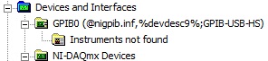
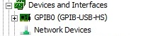
(5) connected GPIB-USB-HS. Scanned for changes on the hardware, peripheral GPIB presents itself to the MAX, but with a weird name announcement its INF file on his behalf. See the screenshots below:
GPIB device incorrectly installed:
GPIB device properly installed:
The strange thing is that this GPIB device was fully functional on my previous installation (see attachment max_report_3-23 - 11.pdf), now reinstall after its unusable (see attached max_report_3-24 - 11.pdf). Looking for GPIB instruments to help Max returns no result, but if I reconnect GPIB-USB-HS to the old system of PC all instruments are detected (for instrument scan error message see attached MAX after reinstall.jpg).
That my new problem is not related to USB-6501, maybe I should open a new forum thread.
-
Timed signal generation TTL with the NI USB-6501 to be read by Arduino Uno
First of all, I want to apologize - I am very, very new to LabVIEW and brand new to the development of the software of control equipment in general. I tried to find an answer to this question already, but I'm not entirely sure what I'm looking for.
I have currently a work program LabVIEW which operates a gun card NI USB-6501. Due to the nature of having a machine that springs from a powerful beam of electrons, we want to assure you that if the computer controlling stalls or fails for any reason, we have built-in security that can stop the gun. Our current idea is to connect an Arduino Uno on a PIN on the USB-6501 and LabVIEW to generate a timed signal, which may read the Arduino. If the signal fails (indicating that the control computer has queued or off), the Arduino triggers a power relay that is independent of the control computer and turns off the gun.
I understand that the USB-6501 operates on TTL signals, so the signal that I should be something in the sense of "output TTL high, wait 1 second, output low expectations, a second, repeat TTL ', but I have no idea how to go about programming in LabVIEW. My first thought was that it is a square wave by using the function "simulate the signal" output, or to have trigger an iterative Boolean signal, by using the function 'DAQmx write', but I don't really understand how do to implement or another idea, or if an idea would even work.
Any advice would be greatly appreciated.
Hi Elizabeth,.
THINK THE STREAM!
When do you DATAFLOW think everything falls in places!

Several problems:
-You have to put that MAKE impulse VI in his own loop parallel to your main VI!
-When you place this generation of impulses in the effects loop ("TTL arduino low-high") you should put the CreateTask and StopTask outside the loop: no need to create/stop the task in each iteration.
-Why are there points of constraint to waiting functions?
-Why is there bent wires? You know Ctrl-U?
-LabVIEW comes with an extensive library of example screws: you looked at all these examples DAQmx?
-Suggestion: Learn more about the "structures of producer-consumer"!
-
Too low current performance with USB-6501
For my measure I connected to an output port (output high voltage, 28 pins) with resistor of 10kOhm to ground (Pin 32). For the active reader to type out in car, I measured a 3.33V voltage and current of 0.33mA. I repeated the same measure with open-drain configuration, which leads to 3.27V and 0.33mA. I use NI-DAQmx and changed the disc type of output with a property node in labview 8.5.1. High-voltage output was generated with labview. In a second step, I put out high voltage with the able Control Panel & automation of DAQmx which led to the same result.
For my measure I'd wait a current higher return especially for active training mode, since the specification indicates a voltage between 2.8 and 3.6V for 2mA. I don't understand why the output current is not 0.5mA which would lead to 5V.
If I do the same measure with the + 5V output (PIN 31) source instead of the output port (pin 28), the current is as expected 0.5mA and 4.8V power can be measured.
For all measurements, I used a NI USB-6501 which has already been tested by an engineer from the Canadian standard.
Hello James Mc.
Thanks much for the reply. To reach the CMOS specifications (between 3.5 and 5 v) I add an external pull-up resistance and use to open-drain output ports.
Kind regards
Priska Studer
-
Display of Acquisition sample done with a USB-4431
Tried a bunch of examples, code the DAQ Assistant, mega-search time. At the end of the road. It's about my first traditional appointment to programming DAQmx after years of programming DAQ followed a long hiatus.
I use a hammer strength IEPE hit to begin sampling of a USB-4431. I'll be post-processing fft; I want ten seconds of data to 4096 samples per second (40960 samples).
As I am acquiring data, I want to update a chart to display the contents of the buffer, adding data to the chart every 125 mS up to what the end of the second 10 captures. Relaxation, start sampling data and acquisition works very well. The problem becomes it to the chart control.
The graph is updated in spurts and incompatible adjustments. The second set of 10 shot finally makes the curve, but it takes anywhere from 30 to 120 seconds to display, sometimes in quick "pieces" with long breaks. Sometimes the initial trigger data gets poster immediately, and it takes sometimes 15 seconds just to display the first 512 samples!
I obviously had something fundamentally wrong here. Could someone please have a look at the code below to me. TIA ~!
void main (void)
{
X_AxisIndex = 0;
NumDataPoints = 512; A sample rate of 4096 samples/second, trying to update the chart each 125 milliseconds.CreateDaqTask();
DAQmxStartTask (taskHandle);
RunUserInterface();} / / Hand
Sub CreateDaqTask (void)
{
It all works very well as far as I KNOW *.
DAQmxCreateTask("",&taskHandle);
DAQmxCreateAIForceIEPEChan (taskHandle, ' Dev1/ai0', 'Hammer', DAQmx_Val_PseudoDiff,-10, 100, DAQmx_Val_Pounds, 50.0, DAQmx_Val_mVoltsPerPound, DAQmx_Val_Internal, 0,0021, NULL);
DAQmxSetChanAttribute (taskHandle, 'Hammer', DAQmx_AI_Coupling, DAQmx_Val_AC);
DAQmxCfgSampClkTiming (taskHandle, "OnboardClock", 4096, DAQmx_Val_Rising, DAQmx_Val_FiniteSamps, 40960); Take 10 seconds of a data value to 4096 samples per second.
DAQmxCfgAnlgEdgeStartTrig (taskHandle, 'Hammer', DAQmx_Val_RisingSlope, TriggerLevel);
It all works very well as far as I KNOW *.The idea here is to launch a reminder all the 512 samples/4096 samples per second = 125 mS so I can view the data in a chart control, update all the 1/8th of a second.
DAQmxRegisterEveryNSamplesEvent (taskHandle, DAQmx_Val_Acquired_Into_Buffer, NumDataPoints, 0, EveryNCallback, NULL);} / / CreateDaqTask
Int32 CVICALLBACK EveryNCallback(TaskHandle taskHandle, int32 everyNsamplesEventType, uInt32 nSamples, void *callbackData)
{
Read the data of 512 points and display them.
DAQmxReadAnalogF64 (taskHandle, NumDataPoints, 15.0, DAQmx_Val_GroupByChannel, buffer, NumDataPoints, & CurrentBufferIndex, NULL);
PlotWaveform (main, Main_Graph, buffer, NumDataPoints, VAL_DOUBLE, 1.0, 0.0, X_AxisIndex, 1.0, VAL_THIN_LINE, VAL_NO_POINT, VAL_SOLID, 1, VAL_YELLOW);X_AxisIndex += NumDataPoints;
return 0;
} / / EveryNCallbackThank you, WW, I'll give that a try.
> For input analog, the USB-4431 has a size of 1 023 sample buffer, and it is shared by all channels. .
Can you tell me where you found this information please? I looked and looked, obviously in the wrong place.
Also, I discovered that if I move the mouse quickly as he tries to redraw the graph, it draws a lot more systematically and quickly, but still not in real time.
UPDATE: I got SetSleepPolicy (VAL_SLEEP_NONE); active.
I thought it was to prevent Windows events interfere with the events of data acquisition. Seems to have the opposite effect here. I turned it off, works great now.
-
How do I turn on/off outputs multiples with a single button using USB-6501 & Labview 2010
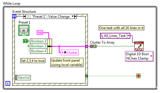
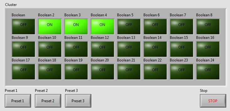
I've written a VI with 24 buttons, one for each output of the USB-6501, for turning on and off 24 relay. Now, I want to add more buttons that activate and deactivate the outputs multiple. We will call these Presets buttons and pressing the Preset button a few outings turn and some turn off. Get it? The VI I've included a screen shot is used to test a transmission controller and rather than to manually select one at a time relay I want a preset button that sets up instantly relays for the next stage of the event.
The VI I wrote uses tasks created in NI MAX.
I am a beginner of Labview, so please try to keep your easy to understand solutions if possible.
Thank you
Kevin
BTW, I'm registered in Core 1 and 2 month next to Richardson, Texas.
Here's an example - you will learn about the grapes, berries, events, etc., in the class, but this will give you a head start. Code is attached but I took a screenshot to give people an idea of how simple the schema becomes:
As your learn about them, I suggest you also make the cluster a TypeDef and make management mistakes, but I've omitted the example to keep things as simple as I could.
Good luck, LabVIEW learning, it is worth!
~ Simon
-
Conduct and variation LED with USB-6501
I have a bunch of LEDs connected to a power supply with an intermediate dimmer. The specifications for all this material is listed below. I'm looking to move from manual control to digital I/o. I have an NI USB-6501 data acquisition, but have never worked with her before and so would like some tips. The goal is to maintain a maximum brightness, but be able to fade the lights of my software. I read several threads on simple power control but that you did not find anything on the gradation.
John.
Lights: (red)
Drive:
Power source: (15 Watts)
http://www.superbrightleds.com/moreinfo/power-supplies/12VDC-CPS-series-power-supply/68/
In order to control something, you must be able to physically connect the 6501, but it does not appear that have anything to connect to. The image of the drive, it has just one button.
-
Trouble with USB-6501 with Labview 8.6 Pro for Mac OS
Hello
I have a unit USB-6501 I try to use with Labview 8.6 for Mac Pro to processor intel.
I have the driver NOR-DAQmx base 3.2 for Mac installed and when I ran "Isdaq", it detects the device and also warned that the firmware needs to be updated. So, I ran the "FWUpdate" for updating the firmware. I double check the Isdaq and it detects the device as "NI USB-6501:"Dev1"(USB0::0x3923:0x718A:014386 B 0: RAW).
Now, when I run Labview 8.6 and DAQmx Base create channel VI and the port of 'physical' wire to the control, nothing appears in the available device.
Also, when I run the mxbaseconfig program, not the existing basic tasks detect the device.
Could someone please help me get this to work? Basically, I need to read and write slow digital data through USB-6501. But, the Labview does not detect the device.
Thank you
Keong,
I do not know what causes this, but place a task create VI before your code and the wire of the output task to the task of entering the chain and try to run that. Please let me know if it works for you.
-
NEITHER USB-6501-24-line digital i/o (OR-DAQ) with LabWindows/CVI 7.0?
Hello
Can I use a recent NI USB-6501-24-line e/s digital (OR-DAQ) with LabWindows/CVI 7.0, although Labwindows/CVI 8.x is required?
Thank you
Dayne
Hello.
In DAQmx Readme, you can see which version of the CVI are supported by the version of current DAQmx. For a map of 6501, 8.7.2 or DAQmx 8.9.5 versions work.
Concerning
-
Hello
Could someone give me some information about whether it is possible to use the
NEITHER USB-6501
As a generator PWM to control the dimming of 18 power LED function?
calendar is not so relevant and if the pulse width can be controlled in the PC itself application the purpose would be financed
Hello ONavarro,
It is technically possible, but please note that USB-6501 as only software clocked e/s digital (e/s static). In other words the duty cycle of the PWM periodocity Ant you want to generate will be determined by a loop software, so depending on your system and the USB bus. I think that you will not be able to get a better rate of loop (ability to change the State of a digital line) less than some milliseconds (depending on the system).
By example, if the loop runs at 5ms, and I want 10 steps in my PWM, this means the period will be 50ms, therefore a 20 Hz base frequency. If you can't reach 1ms, you will get 100 Hz. If you want more than 10 duty cycle value, you reduce the frequency.
And it is NOT stable (loop software 5ms, first delta 5.8ms, then 4.9ms, 5.1ms, 6.7ms, and so on), because it is based on the software. If you need something stable and faster, choose a device with hardware synchronizing.
Best regards
-
NI USB-6501 digital output problem
Hello
I use DASYLab v.11 and I'm working on an interface with the NI USB-6501 where I'm putting a digital high on four ports.
With the module "NOR-DAQmx - digital input", I managed to read the digital inputs of the ' NI USB-6501 ".»
It's only the "NOR-DAQmx - digital output" I can't go to work.
Using 'NI MAX' of NOR I have easily can emmit my four LEDs in the way of my High/Low ports.
But not with DASYLab. When you use DASYLab tension on the ports remains unchanged.
Now, I have a switch module, generating 5/0, directly connected to the digital output module, which is assigned to my four output ports for my task.
I also tried with a module of relay between the two without success. I also tried to use 1.5 above instead of 5 without success.
I use the option 'Bus (0/5 supply) for the module "Digital output".
"NI Max", I configured the ports as "active drive.
Any suggestion of what I might be missing?
Thank you
Martin
Hmm, four ports, or four lines?
A port consists of eight lines. Each line can control an LED (ON / OFF ~ 0/5V).
If you have created a task to dig-out to control a port, 5V to this port sending sets all lines of this port to 'high '.
You need to 255 for each line one too high port (at the bit level: 128 + 64 + 32 + 16 + 8 + 4 + 2 + 1).<- eight="">
Or, you can create a dig out tasks to control four lines of a specific port.
Four lanes of the EEG DAQmx DigOut module.
Each of the channels of the modul will feed a single line of the task/device.
Four switches will then turn the lights, or turn off.
Make sure, that the 'bitposition' is the number of correct line (see picture).
Maybe you are looking for
-
Time Capsule backups causing TC no longer provide Wifi
I had problems in the past two months where my wifi log throughout the day. I kept resetting the modem and my wifi back upward. The problem persisted for two months and I decided to get a modem separate upstairs and one downstairs help regulate the
-
Error message: Startup Repair cannot repair this computer automatically
After an update to Windows, computer does not restart. This have posted on the Forum and suggestions have not corrected the problem. Can someone call me please?
-
How to fix Microsofft library visual C ++ error in Vista?
How can I solve this problem?
-
My laptop has been infected with a virus and I did a ghost to restore the system. Unfortunately, I chose the wrong disc hard Ghost in so packed in the computer Windows Vista laptop has been erased. So I want to know how to download and install again.