Generate sine in FPGA
Hello
I'm trying to generate a sine at 13, 56 MHz on a 5641R. I managed to do it on the host, but now I want to create this on the FPGA, because after I want to achieve a modulation to make RFID. And I need to have all the code in the FPGA.
Does anyone have any idea how I can do this, or an example?
Thank you
Hi Simon,.
You can use Xilinx core generator and IP integration node to create a DDS based waveform or you can create it using LabVIEW FPGA. The LabVIEW FPGA tutorial also explains how to use a LUT with a sine wave, which if you will use only a single frequency can be a simpler way to go.
Tags: NI Products
Similar Questions
-
PtByPt square signal generator for output FPGA
I'm currently building a host vi in which I can choose to send a square wave or a constant value in the analog output of FPGA. I know this might solve using the square wave generator express vi in FPGA.vi, how ever, in order to save using the FPGA card, I want to use the generator function from signal square on the host vi.
The first problem I encountered was square wave generator outputs feature a table instead of a ladder, so can not connect to the output function FPGA I/O node. Then I tried square wave PtByPt. However, the functino description is a bit vague for me. What I get now is a constant value defined by amplitude instead of a square wave. If I set the amplitude to 4, then the wave is a continuous line with a value of 4, and if it's 4 or - 4 depends on the frequency I put. I don't know if it is caused by the definition of wong of the time parameter of the function.
Can someone help me understand how a square on host vi of output wave? Thank you.
Here's the same VI to 8.5. I hope that helps!
Gregory C.
-
How can I generate sine signal long 10ms?
Hello world
I would like to do next: generate a sine or a DC signal for a period of time, 10 ms, that is to say after that, I want that my trips to Earth, so that the next time that I run the program. I use DAQ Assistant and DAQ 6211.
Any help or advice will be great!
Best regards
Pero
pero_kr wrote:
Let's say I have a while loop in my program. When I press "run" the loop runs over and over again, until the stop condition occurs. How long (in milliseconds, microseconds or nanoseconds) takes to my PC to do the operation in an iteration of the loop?
Hope this time was make myself clear. Thank you much for the help.
That depends entirely on what is inside the loop, and what does your computer and what operating system you are using. You cannot create a deterministic loop with a non-deterministic operating system like Windows. An iteration of the loop could take 5 msec, or it might take 5 seconds if the OS thinks it must go off and do something very important, like updating your computer to solve all these security holes that has Windows. You can use call loops, but those who are not guaranteed to operate at exactly the specified frequency since you are at the mercy of the operating system.
I still don't see why this information is important to you. Did you do as suggested and watched the examples supplied with LabVIEW and settle with DAQmx? They show you how to do the generation continues.
-
Generate sine wave with noise when simulating Compact Rio on computer test Dev
How can I create a simulated IO vi. I tried to follow the tutorial, but it did not work. Do I need an array of pre filled with data for the business running or I can generate with one express vi? My IO vi does not seem to enter the case of race ever. What is the process of running this VI? He is running once or whenever the main vi trying some samples?
Hi Bartekluk
What tutorial did you follow? Please post the link and I'll take a look.
Kind regards
-
How to generate sine waves of the evolution of the frequencies with neither 6733?
I have a card ni6733. I want a specific frequency of the output waveform. After a few cycles, waveform frequency must be changed several times without delay. Bandwidth varies from 0.1 Hz to 10 Hz.
I'm new on the map of NI6733, if have no idea about it. I intend to use the scheme of double buffering for waveform generation. Timing here is critical.
Please give the sequence of function (if possible).
Hi Andrew, I found problem in double buffering when using the buffer of size less than 16384 (32768/2). Why? I don't know... also beyong 1,25,000 "stack overflow" error was coming. Anyway, I dropped the idea of using double buffering. Now I use generation of waveform buffer alone without the help of NIDAQMakeBuffer. Instead, I create the buffer myself having data points of variable frequency to set the number of cycles. as demand for time-duration of profile waveform must be generated is limited to 50 seconds, and I use the rate constant update of 1000 samples per second, buffer size if necessary not creating any problems so far (for now). Thank you very much for your generosity. Rahul
-
Simulate the sine wave using LabVIEW FPGA with NOR-myRIO and display in real time
Hello
I'm relatively new to LabVIEW FPGA. I am trying to test (and later apply) controllers high speed on myRIO.
At this point, I'm trying to simulate the sine wave from 1 to 10 kHz using Sinewave generator VI express. I also intend to display the sine wave on the time real (RT) using FIFO. However, I had a bit of trouble to understaing various synchronization parameters.
1. how to encode information about the sampling frequency generating sine wave? (The side FPGA vi requires only the frequency of the signal and possibly phase and does not rate update lines)
2. how to estimate the number of items in a FIFO? (that is, the relationship between the rate of updates to loop (RT), the signal frequency, sampling frequency and the number of items in the FIFO)
It would be great if we could share a very simple program (side host and target) that did something similar.
Thank you
MILIN
Milot,
I think the problem is the type of data in your FIFO. Your FIFO is configured to use a data type of I16. The problem is the number, it displays only ever will be-1, 0 or 1. To resolve this problem, you must send the sine wave as a fixed point data and convert it to a double on the side of the RT. This should significantly improve your resolution.
-
[FPGA] Problem with the sinusoidal signal generator
Hello!
At first I want to apologize for my English is not my mother tongue.
Hardware and software I use is:
LabVIEW 8.5
NEITHER RIO 2.4.1
NEITHER cRIO-9014 (controller in time real CompactRIO)
NEITHER cRIO-9104 (chassis and FPGA)
NEITHER 9264 (16 channels, +-10V, 16-bit voltage analogue output Module)
I made a very simple FPGA VI: a while loop, generator of sinusoidal signal and a FPGA of e/s node in the loop. I've specified the Gnerator settings by following the path:
Frequency = 50 Hz
Amplitude = 1
Phase shift = 0.00
Size of the table look-up = 1024
= 16-bit amplitude resolutionFPGA clock frequency (40 MHz)
But the wave of "sine" I got is not what I wanted to get. First of all, its amplitude is 1 V. shouldn't it be coded on 16 bits? If I wanted to get 1V I should have specified Amplitude as a 3277. In addition, 'sine' is not very detailed, it's look like "steps", as many samples vere missing. What I did wrong? I checked the samples and tutorials, I did everything the same way. A I forgot something or not has not specify other parameters?
Thanks a lot for your help!
OK, I solved a problem. It's embarrassing to admit, but maybe this will help someone else
 I blame my inexperience
The main solution to the problem was changing calibration of calibrated RAW Mode. After that, everythoing works as expected. I had a problem with a sample because I was using a multiplier to control the generated sine wave amplitude. But... She was set to 1 in the sinusoidal signal generator. That was the reason for waveform Gradin. Please, don't laugh too much

In any case, thank you for an answer! It is now resolved
-
Hello
I just started to use LabVIEW FPGA and have some problems with the acquisition of signals. I set up a test project where I try to the issuance of a signal using a NOR-9263 and collated the signal using a NOR-9215. In addition, I measure a signal created by a signal generator sine. During the measurement, I get unexpected values (see attatchment). I think I get into trouble with the FIFO storage. What is my failure?
Concerning
Daniel
My first guess is that you run into a situation where once from time to time, the number of items to be read from the FIFO is not a multiple of the number of outputs to Decimate 1 d Array. When this happens, you will lose data and the first item next FIFO reading doesn't match the first chain, so you will get incorrect values on the chart. Try to change your code so that when you do the reading of FIFO, it reads that multiples of the Decimate 1 d table size, not to mention that this number should also be less than or equal the number of elements to read in the FIFO (as you already).
EDIT: also, you must make sure that the FIFO write never times out. Now you're ignoring this value. Chances are, it won't expire here, but if this is the case, which could also cause problems because you could write only some of the channels before it fills, which still move channels.
-
Hello
I need to convert a sine wave DDS in different signals (teeth of saw, square, triangle) generated in Labview FPGA.
I would be grateful if you could help me find an easy way to achieve this goal.Thanks in advance!
You can use the increment method I suggested for saw teeth unless you increase when the square wave (or sine) is positive, or decrease when it is negative. This method is not the quality of the input except for transitions of comparator signal.
Lynn
-
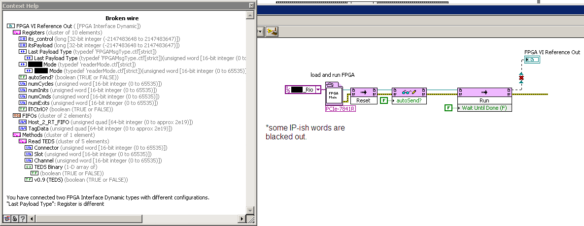
LV FPGA - Front Panel strict Typedefs are not flexible
Hello
When using LabVIEW FPGA and implement a strict typedef on the Panel before the FPGA, this causes issues with the FPGA generated in the PC Code reference. I have attached a picture.
In the code of my PC, I generate the ref FPGA, then use it. In the subVIs downstream, I use the same REF. It works very well. But if I never change the strict typedef and recompile the code FPGAS, can I get the wire cut as in the attached photo. I have to manually recreate this indicator FPGA Ref and cut and paste in all the subVIs downstream, pain in the ass!
One might think that the strict typedef should not update in this manual. You can fix in future versions, or I do something wrong?
Configuration information:
- Open FPGA VI reference is to the bitfile and dynamic mode
- FPGA VI on benchmark is the same bitfile
- Downstream of fpgaRef indicators come bitfile too.
Thank you
Justin Reina
You bind the FPGA reference to an interface or to the VI? I think that if it's related to the VI you should not see this problem, but if link you to the interface of this problem would be understandable. Also, have you considered reference FPGA so a type definition? Then, you only set in one place if it does not break.
EDIT: in case it isn't clear, by binding, I hear a right click on the indicator and choosing configure the FPGA reference.
-
FPGA compilation error sbRIO 9632
Hi guys,.
I'm trying to write a simple piece of code to send a PWM signal to a PIN on my sbRIO-9632 (starter kit 2.0) to order a servo. I used the example of 'control a servo using PWM' and my code is pretty much the same. When I try to generate/compile the FPGA VI, it stops after only 4 to 6 minutes, saying an error has occurred. The compilation appears to hang during the process of the "card".
The example is for a sbRIO-9631 so I created a new project for my robot Robotics and changed the PIN e/s that I use (Port5/DIO9). I search through forums but cannot find a solution to this :/
I have attached my code and the XilinxLog file with it.
Thanks for any help!
MortZ
Hello
Sorry for the late reply! Have you made progress?
Unfortunately, your zip file seems to be disabled on my PC. How it has been compressed?
So what I meant by remove the digital Pulse.vi to generate, is to see if it affected the compilation. Please see if you can compile the FPGA code with the following approach:
Create the new project > add your target sbRIO > add the VI attached to this post to your FPGA target > compile
I think it would be beneficial to you to see if the problem is the compilation itself or the code you are trying to compile.
In addition, you have any another available PC? Might be a good idea to see if your code compiles on another PC.
Please make sure you have LabVIEW Real-time and LabVIEW FPGA installed (it should come with the Robotics module, but I recommend that you check that they have indeed been included).
If the build process fails to map no matter what you do, I propose the following: make sure that the target passes a self-test of MAX. reinstall the Xilinx tools (only if it seems that the issue is not with the code, but with the compilation process itself).
Good luck
Best regards
Christopher
-
DMA FIFO of FPGA compilation error
Hello
I have a cRIO 9074 with FPGA. I tried a simple piece of code to learn how to acquire the data that is generated on the FPGA at a rate of 10 KHz and transfer it to the host VI to treat later in offline mode. However, I meet this compilation error when you compile the FPGA VI base containing a node to write FIFO (photo of the VI attached below). In compiling the report, it is said that there are 256 RAM Block used (the total number is 40), so an error has occurred. The error notification of exact compilation from Xilinx report is reproduced below:
# From the PAM program
# o toplevel_gen_map.ncd - intstyle xflow-calendar toplevel_gen.ngd map
toplevel_gen. FCP
#----------------------------------------------#
"Target part using" 3s2000fg456-4 ".
Design of mapping in the lut...
Guided running of packaging...
Running based on the delay of packaging of LUT...
ERROR
 ack:2310 - type compositions "RAMB16" too found to adapt to this device.
ERROR: card: 115 - the design is too large to fit the device. Please consult the Design summary section to see what resource requirements for your design exceeds the resources available in the device. Note that the number of slices don't notice it that their packaging could not be completed accurately.
NOTE: A file NCD will be always generated to allow you to examine the mapped design. This file is intended for evaluation use only and will not be processed successfully by means of BY.
Mapping performed.
See the report of map file "toplevel_gen_map.mrp" for more details.
Problem encountered during the packaging phase.
Summary of design
--------------
Error number: 2
Number of warnings: 125
ERROR: Xflow - card program returned the error 2 code. Aborting the workflow execution...
Bitstream not created
Time history analysis
What does that mean? How can I fix this error?
Thank you
Bogdan
Hey,.
Have you already tried to reduce the size of the FIFO memory?
Christian
-
I would like to illustrate the effects of the differences on the amplitude, frequency and phase between two sine waves. I already used the sinus function and works well without phase variations. I tried to use the sine wave as planned in the signal generation VI vi, but I can't find a way to make it work. I tried to use a loop for change the entrance of samples, but does not work. I don't want to use the express vi.
Anyone out there an idea to share? Thank in advance!
Ricardo
Have you looked carefully at the example, that I told you about earlier? You can find examples in LabVIEW by going to help > find examples.
This example uses the VI of sinusoidal waveform to generate sine waves. Just look at the chart of most likely down. Look at the entries to the function and you will see how the sine waves you want do like VI.
-
Hello
I use hearing to generate sine waves of different frequencies. Is the a VST plug-in free or cheap for hearing that produces the best sound quality or there are some settings I can do at the hearing in order to increase the quality?
Thank you!
When you start without file and generate tone, hearing allows you to select the number of rate and little sample of the file that is created for the app create tone. The application itself allows you to select the duration of the tone. So, you can use it to generate the tone with a 96 kHz or higher, 24-bit, sampling frequency that is more than enough for what audio, at least.
-
myRIO sinusoid frequency errors
Hello
I have a big problem when generating a sinusoidal signal. I use core FPGA with an Express VI to generate the sinusoidal signal and tuned frequency is not the same result when I measured with an oscilloscope. For example, at 100 Hz out 119Hz; to 1000 Hz is released 1200Hz and 5000Hz was released 5800Hz.
Please I need help as soon as possible for my graduate studies.
the entrance to the generator sine takes a + 32.0. your code did not provide the full 32 bits, and the result was no frequency of course.
I have attached a version update. This should work much better. as I have noted in VI, I do not generally the calculation of the increase of the FPGA code generation. This calculation is usually in floating-point in RT code. But if you need it in FPGA, then, it's a way to do.
Maybe you are looking for
-
Is - harmful to the battery to recharge using a Bank of power?
IS - harmful to the battery to recharge using a Bank of power or a car charger?
-
EQ problem since the update, anyone seen this?
Then got the 10.2.1 update, because then it seems that I can't change the processing mode in the EQ channel more to the side middle, etc, seems to be true for all my instances of the device. Probably something wrong, but what? I almost thought I had
-
I have an Officejet 6500 has more and I'm on a Wiondows operating system has received an error code 252 when I received a fax and fax not happened. what it means?
-
the windows password of my pc is, I forgot that you can do
Ideas: You have problems with programs Error messages Recent changes to your computer What you have already tried to solve the problem Remember - this is a public forum so never post private information such as numbers of mail or telephone!
-
So I kinda a weird problem and I was wondering if anyone else had. For some reason any my palmrest got REALLY hot in like 2 minutes so I stop the laptop and now my speakers do not work. What do I need to send in the warranty support?