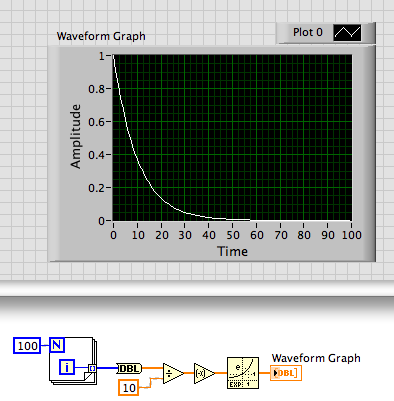
generation of a graph of exponential decay
Hey I'm trying to generate a graph of exponential decay. I tried a few types of different signal generator, but nothing was even close. Can anyone help?
What have you tried? Directly apply the math seems to work.
Lynn
Tags: NI Software
Similar Questions
-
Rapid calculation of the exponential decay constants
Hi all
I try to develop a routine that quickly calculates the exponential decay of a given waveform constant. I use two different techniques, dealing with the calculation of the directions and another using corrects successive integration (LRS). The two usually give the correct time for the input waveform even constant with a significant amount of noise. The LRS solution is significantly less sensitive to noise (desirable), but much more slowly (DFT computations run the order of 10s of microseconds for a waveform pt 1000, while the LRS, such that it is coded in Labview, running at about 1.5 ms). The LRS technique has been developed by researchers at the George Fox University in Oregon, and they claim that they could perform some computation time on the order of 200 US for both techniques. I have been unable to reach this time with the LRS technique (obviously) and attempted to use a node of the library Call to call a dll compiled this code in C. However, at best, I get a growth factor 2 in speed. In addition, additional calculations using the dll seem to be additive - i.e. for four calculations similar running in the same structure with no dependence on each other, the total computation time is about 4 times that of one. In my case, this is not enough because I try to calculate 8 x to 1kH.
Looking through the discussion, I have been unable to determine if I should wait for a performance for C gain well written on Labview well written (most seem to ask why you want to do something external). In any case, I join the code, then you can be the judge as to if it's well-written, or if there is no improvement in performance. The main function is the Test analysis Methods.vi that generates a wave exponential scale, offset and noise and then the decay constant tau is calculated using the VI is Tau.vi. In addition, I am attaching the C code as well as the dll for solving the equations of LRS. They were coded in Labview 8.6 and the C has been encoded using the latest version of Visual C++ Express Edition from Microsoft. Themain VI uses the FPGA VI module ' Tick count to determine the rate of computation in microseconds, so if you do not have this module you should remove this code.
Any thoughts are appreciated. Thanks, Matt
Hi Matt,
After changing the summation loop in your calculation of CWR, the routine runs as fast (or faster) than the variants of the DFT... Anyway: check the results to be sure it is still correct.
-
Estimate of exponential decay time constant - taking tangent lines
Hello
How would you estimate a first order decay time constant? I have a system that loses heat very slowly and I wish assess the time constant of the first part of the data in order to allow more frequent tests (I know it will end by decomposing to).
I know I can make a good estimate based on the initial slope of the curve, but I don't know how to implement this in LabVIEW. Does anyone know how I can make the VI calculate a tangent line to a graph, and to find where it crosses another line?
Thank youHow about using the
VI exponential form
Have the Palette: Screw
Request: Full development system
Returns the exponential fit to a set of data (X, Y) using the method of least squares, less absolute residual or Bisquare.
This VI uses the General iterative least squares method and the method of Levenberg-Marquardt to adjust the data to a curve exponential of the General form described by the following equation:
f = aebx + c
where x is the input sequence X, a is the amplitude, b is depreciationand c is out of step. This VI find the values of a, b, and c that better observations (X, Y).
-
How do you derive speed and acceleration data position?
Hello
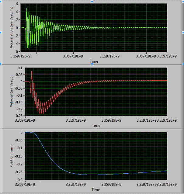
We are working on a project that requires data of distance, speed and acceleration over time. We use the NI 9234 compactDAQ chassis connected to an accelerometer. The accelerometer is attached to a topic plastic cantilevered (rectangular) which is "gathered" - a bit like a ruler on the edge of a table hanging like a diving board. We will gain about 2 k samples/sec. There is no problem getting the acceleration data, it is transformed in speed and distance, which is the problem. There is a link OR a solution (http://decibel.ni.com/content/docs/DOC-4308, see below), but it does not work. I remember in my class of calculation that you integrate acceleration to get the speed, you integrate the speed to get remotely.

This gives us the following graphs:
Acceleration seems good, of course. But the speed looks like it is a sinusoidal signal riding on a curve that dips down and then decreases exponentially. (This dip and decomposition looks like the answer to an excessive vibration.) I expected to be similar to the acceleration, speed, but out of phase 90 degrees (symmetrical relative to the origin).
And we want the position and not remotely. Position would also be a sine wave exponentially decaying.
So, what math should apply?
Thanks in advance,
Shadowfeld
Hello
Conversion acceleration in the speed/movement or movement speed requires the digital integration. In LabVIEW, you can take the accelerometer measures and represent this signal in acceleration, speed or movement by running the example VI (Figure 1) included in the next tutorial for area Developer:
1 excerpts from acceleration, speed and displacement signal processing: http://zone.ni.com/devzone/cda/tut/p/id/4989
Best regards
M Ali
Technical sales engineer
National Instruments
-
Dear Sir
I am a beginner in labview and I would like to solve two differential equations and field them over time:
DX1/dt = (G - K * x 1 (t)) /V (t)
dV (t) /dt = (1/((1-(((G-x1*(K-U))/(G-x0*(K-U)))^((U/(K-U)))-1))*U
G = 7.8
U = 0,166
x 0 = 132
VO = 432
K = 2.02
Could someone please help me and send the block diagram for these two equations.
The graphs of these two variables have to be reduced over time. The graph of X 1 is of exponential decay.
Hello Ahmad,
I made a simple example and put it on our community page. This example uses our ODE solver vis LabVIEW comes with 8 built in ODE solvers. These are all linear system solvers. It seems that your equations are not linear. I suggest using the LaPlace transforms to solve equations.
-
Inconsistent behavior of the object Curve2DPreview with YAxisScalingType
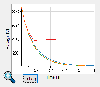
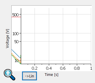
I'm trying to draw some curves tiara with VBScript. The only tool I found is the subject of "Curve2DPreview".
The curves are an exponential decay of voltage. When indicated on a linear scale, they look like this:
I put a button next to the plot to change the logarithmic scale, and when I do the result is the following:
Someone knows how to solve this problem and intrigue in the right position?
More information: I have DIAdem2015, the four curves are curves of waveform.
Thank you
Hi franco__,
You're right, that's not correct. The only workaround is to convert the string of waveform in an X / Y pair of channel and display this. I hope that we can fix the problem for the next version of DIAdem.
Greetings
Walter
-
Low-pass filter before the NI 5112
Hello
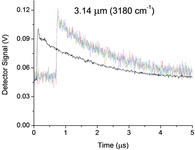
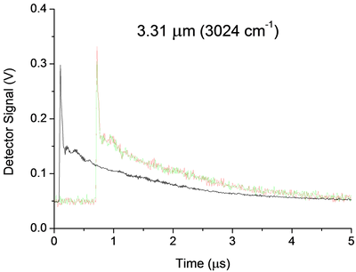
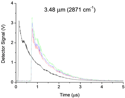
I currently use a 5112 AND measure the signal of an infrared detector in an experience of ring to the bottom of the cavity. Below are three examples of signals. My main question is how I can implement a low pass filter, passive preference, before my 5112 OR undistorted extremely my signal due to the impedance mismatch. Now a few details:
Some unique captures for each wavelength are shown in color, while average 25 pulses appears offset in black. The range and offset are chosen in each case in order to minimize the noise of "scanning". In the case of 3.14um, the noise that you see is about 25 times noise from scanning. They were taken without the limitation of BW and 100 ms/s mode.
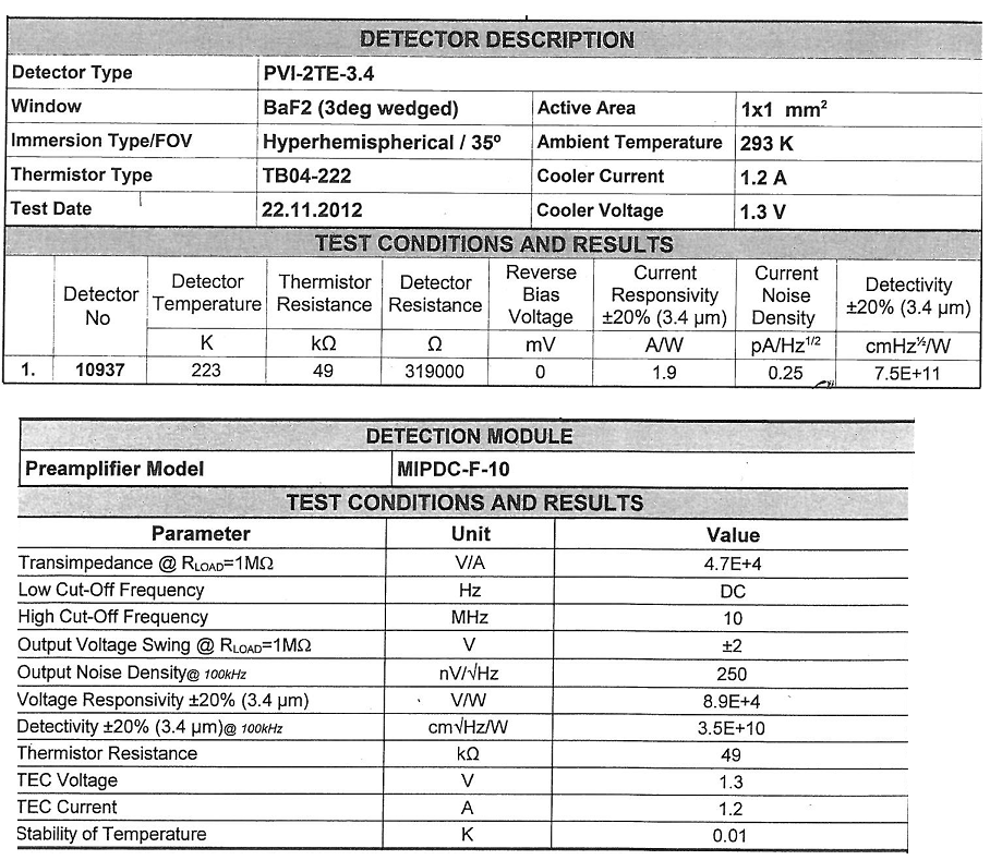
The detector (Vigo MIPDC-F-10) has a bandwidth of 10 MHz. I think it is a low impedance and is intended to be harnessed with 50Ohms, however its documentation confuses me, and I'm waiting for a definitive answer from the provider. 2.4 part of the manual says 50Ohms recommended, however the Datasheet and our map calibration (below) seem to suggest 1 MOhm is recommended!
There are a few strange oscillations with a period of almost 180ns in our signal that I thought were due to the impedance mismatch existed in the system before I changed it:
-Detector
-1 metre 50 Ohm SMC Cable BNC (RG-174)
-Inline BNC connector
-meter 5, 75 Ohm BNC to BNC cable
-Digitizer, DC, no BW limit, 100 ms/s, 1MOhm | 30pF
When I saw this configuration, I knew something wasn't right and I even he modeled in LTSpice and he showed the same period of oscillations. But now, the Setup is:
-Detector
-1 metre 50 Ohm SMC Cable BNC (RG-174)
-BW digitizer, DC, limit, 100 ms/s, 50 Ohm
And we still have oscillations, even if the period seems to have changed to 320ns all about. These oscillations, which remain are 99%, probably due to our drop-down ring cavity experiment, however if anyone has recommendations on possible causes or ways I can confirm it is not because of my chain of detection they would be more than welcome!
Now, the main question. Between the 50 Ohm 1 meter cable and the scanner I would insert a low pass filter. The BW limit has helped reduce the noise, but it can certainly still be further reduced without any lose to our signal. That's because we cut the beginning of the signal and then measure just the the decay time, which is relatively long and smooth (1 to 2 times 1/e US). Thus, in the future I may even want to try to eliminate the oscillations 320ns, but I'm afraid that this much filtering will distort the signal too. Therefore, for the immediate future I'm just looking to 'replace' the filter BW 20 MHz, with something like 1 or 5 MHz.
Of course, I would disable the BW limit on the digitizer to avoid additional confusion, but nevertheless, I'm not sure how to approach the problem. Usually I do a lot of research and try different solutions. However, I don't have access to all components to this work, so everything should be ordered, and I don't have a lot of time to experiment. Ferrites seem like a possible solution, however not sure how effective they are at this low frequency or the way they work with coaxial cables. I know that the filter passes low RC base, but the 50Ohms (or 1MOhm | 30 pF if I change it) seem to make it impossible. I guess an op-amp based one might work, however the large input impedance is the impedance of coaxial cable... etc...
All of the recommendations of the technique or red resources wort would be welcome. Thanks for your time.
A possible way to separate your artifacts electric and the cavity is relatively simple. You take the data at three wavelengths. For each of them, make a simple exponential decay (for example exponential Fit.vi) adjustment to your data, then subtract this signal. You should have something that oscillates on an average. Compare the residual signals for all three wavelengths, either visually or with something like a power spectrum. Anything in the three is probably the electronic (and you could possibly model and subtract it rather than trying to eliminate it). This could break if the rise time of the signals are different, because that will include elements of different frequency.
I am not convinced that you need to filter your signal before taking data. As you said, any filter will distort your final signal. My preference would be to take the raw signal and apply a filtering in the analysis. LabVIEW has a rich filter, so you can experiment later. If you apply a filter before the digitization of data, you take you will never receive data. However, if you know that your data has no component of your proposed cut filter frequency, you should be good. An analysis of the power on your current spectrum should tell you this. Be careful. Your form of rise time may have information you want later. If you filter, you will probably slow it down.
Good luck! Let us know if you need more information.
-
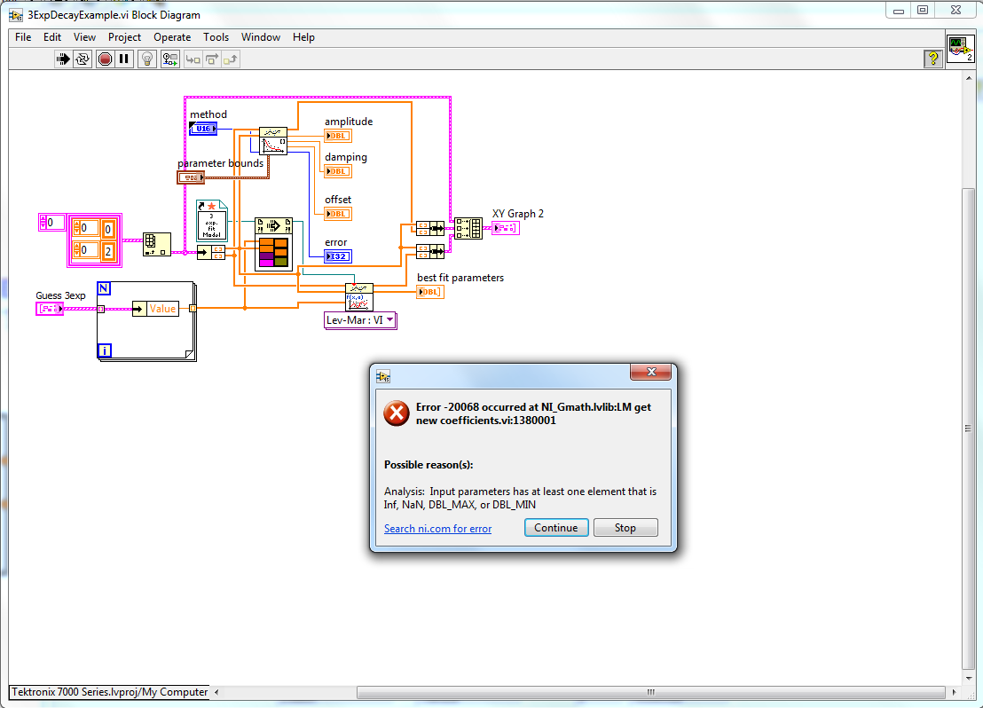
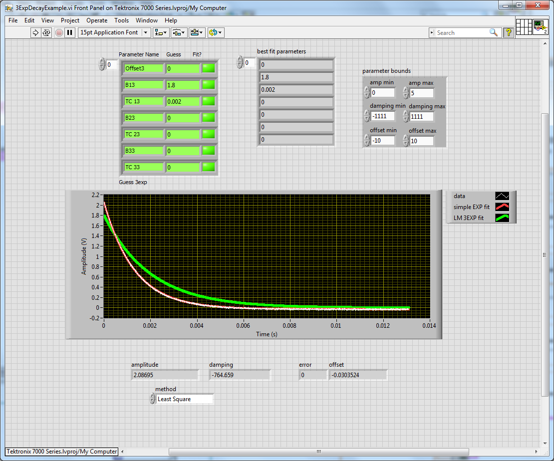
Non-linear curve Fit error 20068?
Trying to do a simple 3-exponential decay curve nonlinear. I have a copy of this work in the other screws, but it doesn't seem to work in this VI. I use "Scalablemultiexponentialdecay" of Altenbach as a VI/template model. Data that I'm trying to adapt are a series simple decomposition RC, yes I realize that should not have 3 exponential components, it's just the model data. I am able to adapt with the Fit exponential function built in to the Math palette, but which only works if the input bounds parameter is wired and with rational constraints. However, I get an error on the adjustment of the non-linear curve that I understand not (photo attached) indicating that an INF or NaN is done in the settings. I don't see where this is going...
Any questions or help is appreciated.
I thought so, only 0 s for the 2nd two exponentials. But, if I replace all the guess seededes with the same as the simple exponential Installer, it converges without error. I guess I didn't know it was that sensitive. Thank you.
-
Try to get data of almost static load of the 9234 module with IEPE sensors
I am train to acquire data of load which should be essentially a function of the square wave loading. The current configuration I have is cDAQ 9234 on LV 8.5 module that I used to start a module of 9233, I had, but after looking for here and that it seemed to me that the 9234, with DC coupling, would allow me to gain the quasi-static load (the load is applied for 2.5 seconds) and not only the load change whenever the load has been applied or removed. So, now I have connected 9234 and I get almost no change in output regardless of whether I got DC or AC coupling selected in MAX. In addition, it always seems to be only to register the initial support change, as before - it's the biggest concern I have.
I had previously configured as a voltage signal and just put across the entrance, which at least made me reasonable support changes when I used the 9233. I expect at least that I would see the same or similar values with the configured 9234 in AC mode. If anyone can shed some light on this I would be very happy.
Here are the technical details of load cell: http://www.dytran.com/img/products/1203V.pdf
I have also attached my code, in which case it might shed some light on the question (please, be gentle - I do not know there is a better way to code this, but I have tried different methods cleaning cycle not properly).
Thanks in advance for any help!
John,
Both the sine part and the exponential decay are indications provide excitement from HQ or using a sensor that uses AC coupling. Looking at the datasheet that you have linked and the site Web of Dytran, I can't determine if the load cell has any kind of internal coupling of AC. I would recommend you contact Dytran and explain the behavior that you see a load constant to see if this is expected behaviour or not. It is possible that the scale is intended primarily for transient or dynamic loading and was not supposed to measure static charges. Let me know what you hear from Dytran and we can continue to resolve this.
-
How to generate curves under labVIEW
Hi all
Can someone please tel me how to generate the following curves under LabVIEW.
Haversine curve 1.)
2 Lorentz curve.)
3 bell curve.)
4.) exponential rise curve
5. exponential decay curve)Note: Entries required for this curves are Amplitude, Phase, Offset
Frequency and number of samplesHave you read the second part of my post above?
-
Noise daq signals sent through an RC circuit
Hello
I'm trying to source various signals of voltage AC / DC through a device that contains resistive and capacitive. I'm doing some testing on very simple circuits - a polarization of the square wave out of an Ao of a DAQ 6368 route through a 1mW resistor, then a current to voltage converter sends a voltage in the AI 6368 channel signal.
With just a resistance, everything works fine - accurate readings of voltage/current, low noise, etc. But when I put a capacitor in series with the resistance, I get intense noise across a very broad range of frequencies. A 10pF capacitor double the noise, and a 100pF capacitor multiplies by 10 x or 15 x. The circuit, I am interested in the measure will be about have capacitance 300pF, more an another 300pF of involved additional wiring.
I'm doing something obviously wrong, capacitance is inherently ruin amplifiers?
I feel like I should see nice exponential decay or splitters of a capacitor, no noise from wide band/HF. Take a look at the photos I have attached with the included fft - they are taken to a 0 V DC bias circuit, showing the current measure in units of microamperes (I posted a similar question a forum recently switch and have determined that the problem is not the switch, but parasitic capacitance in the switch).
Thank you!
EDIT: added some pictures of 10 Hz 100mV pulses of square waves, all online is the trace of current time. The resistance of 1Mohm one looks great - 100nA for 100mV makes great sense, low noise, etc. But with the capacitor 10pF, wise capacitive spikes, but whats up with the rise in noise?
Hi Lynn,
Thanks for all the advice - the noise was much higher in frequency, up to 10 kHz region. I finally found my noise problems caused by Earth or impedance mismatch between my PXI and my bipotentiostat loops, so I'm doing the experience entirely using components PXI.
Best,
GIM
-
I built a VI to build MAG/PHASE plots using FFT of the range of signal processing. This is a small VI & seems a bit simple. However, to check if everything is working correctly I built a 2nd & 5th order pole fictional system that I know that the transfer functions: 10/s+10(1/(s+0.5)+1/(s+0.5)+1/(s+0.5))+1/(s+0.5))
2nd order system:10/s+10(1/(s+0.5) Note that these 2 systems are in exponential decay in the time domain.
It seems that I solved my problem. I have been using the FFT properly throughout. I had my incorrect analytical model. The FFT told me this throughout, but I doubted that I was with them properly instead of questioning my analytical model.
-
Problem to adjust the data using the algorithm of lev - mar...
Hello
I'm a casual user of LV, and I need signal level using a non-linear custom model. The signal is basically a decay of exp (order 1) with a continuous component, so it's pretty simple.
When I apply the routine of Lev - Mar's non-linear editing, I've always had the famous "an exception has occurred in externally called by a function of the call library node. This could have corrupted memory of LabView. Save any work., etc.. VIwas stopped to node "" a call to "NI_AALPro.lvlib: Real - Decomposition.vi of SWINE vesicular disease.
The thing is I've already adapted successfully some basic (linear model) data using this form of Lev - Mar non-linear... but it won't work this time... and I don't see why.
Could you watch my VI and model definition and tell me what I need to improve, and what might cause the problem? The main VI (TPV_Fit_ExpDec1_v1.0.vi) open a text file that contains my data (3 columns: time, a pulse (not useful for editing), the signal to fit). At the beginning, I isolate the part of the signal that matches t > = 0, because it is where begins the exponential decay. So I want just to get the part. I join the main VI, a txt file containing typical data, and made the VI that define the model to the lev-mark function.
I would appreciate your help and suggestions!
Thank you very much in advance.
MY VERSION of LABVIEW is the 8.2
JB
Here's a quick rewrite. You should ALWAYS figure the curve for the initial parameter estimates see if they are in the ballpark. Rather than modify the data, you could just put the weight to zero for negatvie x. see if it works better.

-
MyDAQ - generation of a digital signal and display on an analog waveform graph
Hello
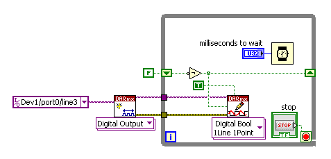
I use the MyDAQ OR generate a digital waveform with a Frequency adjustable. This is implemented in a program, I already wrote it, which generates a TTL 'like' impulse out of the sound card. I display the result on a graph of analog wave form, and I would like to be able to display the digital signals generated by the myDAQ on the same graph. (Not in the same time, one or the other, activated by a button). I've been messing around with tables and conversions, but I can't really do with all this.
It's the vi, I did to generate the digital signal of frequency with MyDAQ. Any suggestions on how to do this if the following is false, would be great too, as I just got the MyDAQ a few days ago. I think there must be a better way, but it's the best I could come up with so far.
Hi Jonny,
The General logic, that you use to create a digital pulse train is very good. This VI you wrote should work and create the pulse train based on timing of software (which is fine because you have not DIO clocked by the material on the myDAQ anyway). However, it is generally advised to start the DAQmx task just before your time loop and then disable the task after the while loop when you press stop.
For reference, there are a few examples of good enough LV that I recommend you watch too much for this application. If you try just to create a digital pulse train, the example Gen dig Pulse Train - Continuous.vi is a good example that uses a counter to create a digital pulse of your desired frequency train. It is generally the preferred method to create a pulse train, if you have equipment available to do (the myDAQ there a meter). Otherwise, there are a few examples DIO who write continuously in a digital line / port.
If you are unfamiliar, you can find the examples by clicking Help > examples find... into LV then navigate to hardware input and output > DAQmx > generating digital impulses or the digital generation.
Also, here is some additional information on the myDAQ and its counters:
Hope this helps.
Chris G
-
Excel graph legend formatting - report generation tool
Hi all
I am currently using the Labview 11 report generation tool and do not understand how to change the font for the legend of a chart properties. This is a screenshot of an exit from the attached example.
Help file for the Font.vi graphic Excel said it should be able to change the caption, but I can't seem to understand how to configure it to do so. If anyone can guide me through the steps or tell me what I'm missing, I would be very happy.
Added minor corrections (deleted end characters of the line of the column and row headings).
Ben64

Maybe you are looking for
-
Cannot read memory Flash USB UHYB-064GH .avi files
Hello I recently bought a 64 GB of memory Flash Toshiba (stick). This model UHYB-064GH.Right out of the box, I plugged the USB on my Windows PC. I am running Windows Vista.I tried to transfer a number of files video .avi to the device, taking about 1
-
I have yet to receive the hard copy of my certificate of Microsoft's digital learning
Not received a certificate I have yet to receive the hard copy of my certificate of microsoft's digital learning.
-
E1550 cannot access hard drive NTFS.
I had already posted about problems with the E1550 is not able to recognize NTFS formatted hard drives. After several attempts and reformats I was finally able to run and has been able to back up my hard drive NTFS system files. Now, little more tha
-
1606dn RT of Windows and LaserJet Pro - does not
HI - HP Windows 8 page info (here), the HP LaserJet Pro 1606dn should be fully supported in Windows RT with a driver in the OS. However, it does not work. On my Surface, running Windows RT, when I go to settings to laptop, then peripheral, the 1606
-
QML Desgin Mode: the "bb.multimedia" module is not installed
I using multimedia elements in my application and when I open the design view in the QML Editor, I get the following error: Problem loading qml file: "bb.multimedia" module is not installed I read in the forum that some users have trouble linking to