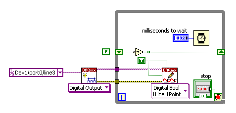
Generation of digital signals through external trigger pulse on PCI 6251
Sir I want by NI 6251 because I read it has the ability to generate and acquire digital signals on port 0. I want to know that can I generate external clock wave triggering (providing impulses to a line on the acquisition of data)?
Hi Ali211,
Yes, you can use a source of sample for the digital input/output clock external clock. You can connect the external clock source to one of the lines PFI (PFI0-PFI15) and specify the source clock sample like this outer line of PFI.
There are some shipping DAQmx examples that you can start with. Find the examples by clicking Help > find examples in LabVIEW.
DAQmx continually reading digital channel with External Clock
DAQmx channel External digital writing Clock
Hope this helps.
Chris G
Tags: NI Software
Similar Questions
-
Cannot receive digital signals through Media Center after local supplier upgrading to digital cable
I hope someone can help.
Dell XPS computer
Windows Vista 32-bit
ATI Theater 650 Pro TV tuner
Recent upgrade of our cable system has left me without all the digital signals being recognized by Windows Media Center. Have still 13 first typical analog signals. I tried everything to get digital. Here, they are identified as XX - 1. Apparenty the TV Pack Upgrade will solve the problem, but I can't seem to download right from my computer (or at all). Any ideas.
-
NOR-6289 DAQ latency for the generation of digital signals
What I want to achieve is less than 1 second latency between the update of several digital waveforms and see these values appear on the digital output pins. For example if I have 16 digital output channels in my task and I am writing 127 samples for each channel at a rate of 1 every 10 ms sample, then I update the waveforms in Labview that are sent to each channel, I do not see the new values on the pins of the output for about 21 seconds. FIFO size onboard for the 6289 is 2 047 samples. At this point, I guess this latency is unconstitutional by the FIFO on board - but I could be wrong.
If the FIFO on board is shared by all channels in a task, a sample of each waveform is generated to the output every 10 ms, then I would expect latency (2 047 samples/16 channels) * 10 ms/sample = 1.27 seconds. However, I still see latency of approximately 21 seconds. Is there something fundamental about the FIFO on board I'm misunderstanding? Or is there something going on in the PC buffer which adds this latency?
I enclose my VI for reference. NOTE: The attached VI only has 2 channels for simplicity again it shows the same latency as the example on channel 16. I had a loop analog acquisition as well to monitor outputs from the digital PIN.
Thanks in advance.
The FIFO is not per channel, each line is a little and FIFO stores all of port 0 as a single sample (the lines that are not used in your job are hidden and not updated). If your sample of 2047 THAT FIFO clocked @ 100 Hz will take roughly 20,47 seconds to build completely. There is also a FIFO in the software (the size of it is configurable) which stores data before their transfer to the device. The pilot will always try to keep the complete material if there are data to generate, FIFO which is good to prevent cost overruns but bad for latency.
If I have LabVIEW 2013, I have not installed on this PC and so I can't watch your VI. I'll try to give some suggestions anyway...
One way around this problem is to use non-regeneration (not sure if you're already or not) and to limit the speed at which you write to your task so that the FIFO is never complete (once the data is written to the device, you cannot remove it from the FIFO). To limit the write speed, try to look at Total "samples per channel has generated" (I think it updates quite frequently on the useful USB devices) from the "current write Position. Both are DAQmx writing properties. Only write data to the task when the difference is less than a threshold.
You might consider the inverse would be output just at a faster pace with duplicate data. For example, [1, 0, 1, 0] @ 100 Hz = [1, 1, 0, 0, 1, 1, 0, 0] at 200 Hz.
Best regards
-
Integrate the external trigger into camera (PCI-1424)
Hi all
I use a PCI 1424 acquisition card to take the image of a Kodak "camera".
Currently, I put the camera on a continuous mode - in which the camera give me frames one after one. I am able to 'snap' or 'capture' images of MAX with the help of the camera file. I can write a simple VI for 'break' a single image in LabVIEW.
Now, I want to go to the single camera viewing mode. In this mode, the unit will display a single image to a trigger signal (the rising edge of a singal TTL).
I wrote a short program for parallel port allows to send this signal triggered at the camera. The increase in power to the camera temporialy, I know that the camera captures an image.
However, the question is how can I nathalie caron this image?
What I do now, is to select 'snap' a picture to the MAX and allow a delay of 10 sec. After you click on the snap, I'll go to LabVIEW and send the trigger signal to the camera.
However, in MAX, I altenativley had a black and white image that is of the Court a false image.
does anyone know the reason?
and how do I integrate the VI trigger in the captuire VI image, so that I can finish the task of single capture inside a VI?
There is a sample VI "Grab.vi triggered" in which user can set waiting time and other properties for IMAQ1394, but I do not know how to PCI1424
Thank you very much.
Dear John,
I have attached this VI.
LabVIEW 7.1
Framegrabber: PCI 1424
Trigger the camera: after set us the camera in mode single shot (by rider material), I just need to send a signal of TTL and the camera will trigger in the front of this signal. So I schedule a pulse to the OID 0 pins at this TTL signal output.
-
Measurement of voltage deferred with a start from a pulse TTL (PCI-6251, OR DAQmx)
Hello
What I do: gain a measure of tension after a certain period of time (order of microseconds) when we observe a TTL pulse, lasting about 1-100 microseconds. What are the options I to do thins?
PS. If this problem is solved in a C code example, please point me to the right direction. I saw examples of NOR-DAQmx, but not a not spot something like this.
Hi hum-human resources management.
The example of DAQmx ANSI C Analog In\Measure Voltage\Cont Acq - Ext Clk - Dig start shows how to use DAQmxCfgDigEdgeStartTrig() to activate a digital start trigger. It also illustrates the continued acquisition, clock to external sampling and all events of samples N; for a simpler starting point, look at analog In\Measure Voltage\Acq-Int Clk-Anlg start and try to convert to using digital analog INSTEAD of triggers.
However, this will start acquiring exactly when the trigger occurs, not after a period of time fixed. Use DAQmxSetStartTrigDelay() and DAQmxSetStartTrigDelayUnits() to add a fixed delay between the trigger and the beginning of the acquisition. Help OR-DAQmx C reference (which should be on the start menu under National Instruments > NOR-DAQ) lists the valid values for the property of units.
Brad
-
analog input external trigger 6015
Hello
I was able to configure my 6015 to accept an external trigger to start a measurement of analog input (with a # set of samples and freq). However, what I want to do is to set up so I can send a 20 kHz signal to the trigger, and whenever the trigger detects the signal, the device would take a measure of the tension of each of the two channels. He would then save this memory on board and allow me to read the data later. That's what I can't figure out how to do.
If he put in place such as I have an asynchronous callback and read data after each pulse, it takes too much time in my application. I want to get a measure for each external trigger pulse (the freq may vary higher or lower, it's why I can't put just a freq - I need to use the trigger) and these data saved in memory on the card for me to pick it up later.
Is this possible with the 6015? Another tip? If so, can you please show a few snippets of code in VB.NET or c# .NET?
Thank you
Joe
Hey Joe,
I think that your application should work fine with the 6015. I mentioned only the buffer size as previous your post said 'I want... these data stored in memory on the card to grab me afterwards,' and especially supported in NOR-DAQmx devices (including the 6015, PCI E Series, the new series X PCIe and PCI M Series) don't work that way. They have permanently transfer data in a buffer in the memory of the host throughout the acquisition PC, and they have enough buffer on board to avoid negative/overflow buffer overflow errors at their maximum supported rate
Brad
-
Sync to external trigger in conjunction with a nearest pulse frequency device fixed...
I am writing an application running a scan frame. One axis of the scanner runs at a fixed frequency. I use a scanner high speed 5105 to get the data. The slow axis of the scanner is controlled by a servo with an analog input. I have will probably use an M-series card for analog control, but can also go with a 6713 (output only) or another Board. Fixed frequency Analyzer provides a clock line, I want to use to drive the 5105. In addition, the analog card must be synchronized in this. The entire system should be able to accept a trigger external devices, as it starts scanning at the edge of clock on next line.
I'm not quite sure about what would be the best way to do it. External triggering from other devices will be an indeterminate pulse width, so I can not just use it as a portal for the line clock. I am reluctant to do it in software (IE via the detection of changes on a digital line) because I want to be reliable started the next clock pulse. I have taken into account things like a counter/timer with a relaxing break, but which could lead to drift between the narcotics control and frequency scanner fixed. It seems just more complex that I think it should be, and it feels like I'm missing a simple way to do it.
Any suggestions?
Hi cshl,.
Good to know - the 5105 has a duty cycle of tolerance of 45-55% (mentioned on the page of the form), so that is why you cannot change clock speed from 3 to 12 MHz on-the-fly (though if you make small incremental updates over time, it would be theoretically possible).
With the additional information in mind, you might want to try the following on the 5105:
Use the external trigger as a trigger of departure (arm of acquisition).
Use the line as a signal reference clock (with a position of 0 samples for reference ~ 7500 are after initiation).
The problem with this is that you will have to re - trigger on each line - 5105 has a 2.4 rearm us time (also mentioned in the page on record). If this is unacceptable, another way that I can think of is to use a clock to external reference in PLL internal clocks of the bezel to. If you can provide a stable, a clock accuracy 50 ppm which is synchronized with your scanner within reach, would solve the problem of drift over time without having to re - trigger on each line (only acquire data continuously). This clock frequency must be between 1 MHz and 20 MHz in steps of 1 MHz.
We have no Council can take in an external variable clock up to 12 MHz (on-the-fly), but if you wanted to compromise a little bit the 6115 can enjoy up to 10 MHz, and has no obligation to cycle to 45-55% so it's maybe interesting look in.
As far as AO goes, I assumed that the clock line is declared after the quick scanner has completed his turnaround (ideally you do not update the zone of OCCUPATION during the lead time). If you have a signal Analyzer that you can use instead probably easier. If not, our peripheral series M and X series (but not the series AO 67xx) offer reference clock feature so if you go with the idea of reference mentioned above clock it may be easier to simply PLL the clocks together. These cards in a PXI chassis or are they PCI form factor?
I don't know what you mean by the sticking point about the need for two triggers. I think the idea is that we use the external trigger to arm the 5105 and clock line to trigger each record. However, if you do not need to generate a pulse double based on the clock of your line then you can use counters to do (our counters are redeclenchables with time to rearm in the ns range).
Best regards
John
-
MyDAQ - generation of a digital signal and display on an analog waveform graph
Hello
I use the MyDAQ OR generate a digital waveform with a Frequency adjustable. This is implemented in a program, I already wrote it, which generates a TTL 'like' impulse out of the sound card. I display the result on a graph of analog wave form, and I would like to be able to display the digital signals generated by the myDAQ on the same graph. (Not in the same time, one or the other, activated by a button). I've been messing around with tables and conversions, but I can't really do with all this.
It's the vi, I did to generate the digital signal of frequency with MyDAQ. Any suggestions on how to do this if the following is false, would be great too, as I just got the MyDAQ a few days ago. I think there must be a better way, but it's the best I could come up with so far.
Hi Jonny,
The General logic, that you use to create a digital pulse train is very good. This VI you wrote should work and create the pulse train based on timing of software (which is fine because you have not DIO clocked by the material on the myDAQ anyway). However, it is generally advised to start the DAQmx task just before your time loop and then disable the task after the while loop when you press stop.
For reference, there are a few examples of good enough LV that I recommend you watch too much for this application. If you try just to create a digital pulse train, the example Gen dig Pulse Train - Continuous.vi is a good example that uses a counter to create a digital pulse of your desired frequency train. It is generally the preferred method to create a pulse train, if you have equipment available to do (the myDAQ there a meter). Otherwise, there are a few examples DIO who write continuously in a digital line / port.
If you are unfamiliar, you can find the examples by clicking Help > examples find... into LV then navigate to hardware input and output > DAQmx > generating digital impulses or the digital generation.
Also, here is some additional information on the myDAQ and its counters:
Hope this helps.
Chris G
-
How to set a start and a trigger digital stop conting number trigger signals
Dear all,
This is an application for the acquisition of data that I don't know how to set triggers. The trigger signal is a sequence of rectangular pulses. A plot of X - is necessary. The interval between signals start of X are the same. So, I need to count signals trigger to know the value of X. And the value is analog signal. If the trigger interval corresponds to dx, my range of measurement is lying will begin with the rise of the m trigger signal - th with X = m * dx, then it stop at the rising edge of the signal trigger of the n - th with X = n * dx.
But I don't know hot to make this trigger + counter. The attachment shows a schematic representation of the measure. Can anyone help?
Thanks in advance.
Best,
Jiangjun
Set the meter to measure the pulse in continuous or over mode according to your requirement.
Use the source of synchronization as the trigger pulses & configure rates at least 100 times rate of relaxation. Then compare the value count against'm & n' & generate the impulse on the PFI lines or the port pins.
I guess you know m & n values.
The other way is to configure to tell it to count the no. rising edges. Then compare this number with'm & n' bones & generate the impulse on the PFI lines or the port pins.
-
How to read digital signals with pre-and post-trigger on a card PCI-6251
I have 22-bit parallel position of data entering TTL lines to 16 kHz with a pulse of marker that says when the data is valid. I also have a fault line which gives an impulse when an error condition is met. I want to read in the 22 lines of position with 500 positions of pre-event and post-event 500 data when the fault line says. How do I pre and post-déclencher lines digital input on a card PCI-6251?
If this is not possible on this map, which maps PCI would be possible?
-
niHSDIO dynamic generation and Acquisition using LV configure Trigger VI
Hello!
My experience is limited within the environment of digital programming; Nevertheless, I have worked on this problem for a few days and would appreciate some comments if possible.
I am trying simply to generate and acquire a duty cycle of 50% of 8 MHz TTL pulse train on a PIN DIO of the PCI-6541 and acquire back from the signal on another axis of DIO. I have a connector corresponding to the embedded 6541 VHDCI connector which of course the generation and acquisition DIO welded pins to provide a loopback effect.
In short, I use the niHSDIO configure Trigger VI (instance--> start Trig: SW), niHSDIO send software Edge Trigger VI and write Named Waveform VI (instance--> data: 1 D U32) in the generation section. For the section of the acquisition, in short, I use the VI of waveform Fetch niHSDIO (instance--> single record: WDT).
I see results in the waveform acquired showing the generated and acquired digital TTL pulse on the respective DIO pins train, but I can't seem to get my 8 MHz frequency requirement. In addition, the lower part of the assignment of pin DIO, more frequency. Unfortunately, due to the configuration system required, I have confined myself to pin 12 DIO for the generation of digital pulses. Even with a 50 MHz clock frequency, I'm ~ 6 kHz of frequency acquired max. I looked at changing the parameters of the wave form VI named write, but it is not possible because the VI call a library function node. I also tried to generate a waveform of 8 MHz through a VI of generator of digital model, but I do not believe, you can trigger on generated waveforms? It seems that you must generate data using a simple loop to as a counter and sending the result to the waveform VI named write. Are there other ways I can simply generate and acquire a digital signal of TTL of 8 MHz (no external connection)?
In any case, any kind of feedback would be greatly appreciated.
Thanks in advance for your time.
Dan
Dan,
Sorry about the nomenclature. I usually use 0 x or 0 b for indication of radix, it is not necessarily a kind of standard, just what I used in my old days of the Assembly.
Looks like you have a knowledge about the data. Basically the material is just save in DRAM an array of words of 32 bits, with each bit corresponds to a data channel and each element being generated to the sampling clock rate you enter to your vi. Everything else is just easy data manipulation or usage. The interleaving method is just as I like to create a toggle model. You can easily do a loop with an inverter and feedback node or use on the construction in screws to signal generation. In addition, you can use the software digital waveform editor or control panel test to generate the county or toggle modes.
Give us an update when you enter the laboratory and let us know if you encounter any other disorder.
-
Generation of pulses using PCI-1428 to CC1
My laboratory uses an external signal generator to generate a pulse to trigger a line scan camera and continuous acquisition of image acquisition card. The lab has just acquired a new camera and unfortunately I can not use the external trigger on the camera connection. I understand that PCI-1428 cannot external signal to a line of camera control. I tried to generate a pulse of MAX, but he won't let me have a pulse with less than 24 US pulse width.
So first, I was wondering if there is a way to generate a pulse with less than 24 US of MAX pulse width.
And if this is not possible, is there a way to generate a pulse of Labview similar to he'S generation.vi of pulse but he sent via the CC lines for the order? Also, how can I program it to make the generated pulse is sent as soon as the frame grabber receives / detects the start of the external signal?
Thanks for your help.

Don't know who did the file of the camera, but the 1428 can generate pulses with a period of 40ns on CC1 (a time base internal 50 MHz is used at the moment of high/low pulse). You can use NI Camera File Generator to modify existing camera files:
http://sine.NI.com/NIPs/CDs/view/p/lang/en/NID/14207
It has good documentation for how to configure the settings of the pulse. If you still have problems, you can view the camera file, let me know what you're trying to use the mode, and which calendar you want pulse and I was able to address the issue, but I recommend trying OR Camera File Generator first... make a backup of your file to camera to keep your original autour.
Hope that helps,
Brad
-
problems with several hr2000 + external trigger mode
I hope someone can me halp on this problem:
I need to acquire spectra with two hr2000 + and a nirques256 with labview external trigger mode.
The external trigger mode is done by another pc and also the train of pulpse generator.
If a trigger after I'm going to generate a 100 impulse every 20ms for each device through a dedicted Council.
If I only work with ghosts at times things works fine and the system is very stable, BUT if I work with two or three spectres by now I have a really strange (maybe for me) problem with the timeout.
This is due to an incorrect number of pulses:
If I work with two device then I need to produce pulses of 200 each 20ms but my spectrometers provide data every 40ms, but I need to equip every 20ms
If I work with threedevice and then I need to produce pulses of 300 each 20ms but my spectrometers to obtain data each 60ms but I need to equip every 20ms
Thus, in this way, I lose the synchronization of the three councils.
An options may be to use a dedicated pc for each device
I acquire the signal via usb and the problem is maybe duo to the bus
I think maybe the problem is duo to the vi block! Maybe I can use single istance at times when I call the procedure
Thank you
I just solved the problem: it was a problem with reentrancy
Default LabVIEW use not reentrant execution
-
initialization of the fgen on external trigger
Hello
For NI_Virtual bench with the BNC switch, we can trigger the function generator to start the square wave? I mean, I want to relax, so I have the beginning of the square wave
You cannot trigger the function generator to start in response to an external signal.
However, you can export a signal only pulses when the FGEN starts the external trigger BNC. You can do this with the entry point to 'Dig deeper the Signal to export'.
Kind regards
William Earle
OR R & D
-
sample clock adjust external trigger
I am trying to use a source of external trigger non - TTL (square wave ~ 8 kHz from 0 to 1.4 V instead of 0 to 5 V) as the clock for an analogue waveform output voltage. Is there a way I can manually change the threshold used for the clock source so that I can get this working?
I'm trying to avoid having to solve this problem at the hardware level, which in my opinion, is to build a comparator circuit to generate a trigger signal TTL of my 0-1, 4 a signal trigger V square.
If not, is there a way I can generate a TTL signal that is synched to my trigger signal 0 to1.4 V ~ 8 kHz wave square using these maps NOR: PCI-6115 or PCIe-6323?
Thank you!
Cecinix, you are right. The sample of the signals clock are specified to be TTL signals, which means that the minimum thresholds of high voltage on the PCI-6115 and PCIe-6323 are respectively 2.2 V and 2,0 V. Digital/PFI input thresholds are listed in the data sheets of the devices, so that they are material defined. Unfortunately, given that all the digital inputs on the card you mention expect tensions TTL, it's something that you have to fix in the material. A comparator circuit could operate as a network of transistors of pull-up.
What generates the square wave? Would it not viable for generating a signal of TTL clock on your NI DAQ card and export this signal to the rest of your system? In general, a digital system is quite tolerant of extra tension a bit, so it's maybe easier than adding voltage conversion circuits.
Kind regards
William R.
Technical sales engineer
Maybe you are looking for
-
AMD Radeon HD 6570 (TransAM): amd radeon hd 6570 second monitor
My original system was connected to a HP 2310e monitor using DVI port on my GPU (AMD Radeon HD 6570 (TransAM)). I found a HP W2371d monitor to use as a second screen, bought an HDMI cable that I had planned to use on 2310e and then use the DVI port
-
Automatic stop when you use the CD/DVD on the 1900-803 Satellite player
Ive had problems with my 1900-803 for the last 3 months. whenever I use the cd/dvd drive, my laptop turns off without warning after 15-20 minutes. It also stops if I try and play all the video files or scan my hard drive for viruses or spyware. is it
-
I just bought a Motorola e Moto Smartphone a week ago because he says WIFI / 3G. I thought that this meant that if there is no available WIFI, I could just flip a switch and connect to the Internet via 3G. Is it not, how does it work? I couldn't figu
-
My signal processing Toolbox is empty, I can't create signals
The attached picture can explain better than me. But I'm trying to generate a signal but obviously that the tools do not appear on my VI.
-
Can not reach a particular site
I am running Windows 7. Nine days, in the morning, I had no trouble to get to a site that I used every day. Two hours later, I could reach is no longer. It is a form of social media, but not the type of current. You use Internet Explorer, Chrome, a