Generation of frequency hopping signals
I work with 5661 + 5671.
I want to generate the signal with 5671 to frequency hopping. The frequency band is 2400-2500 MHz, and the jump rate is a jump by image (1.024ms) or 976 hop per second.
I also need to be able to test the recurrent signal with DAMA 5661.
We can run these jumps tests with 5671 5661 +?
Thank you
Chen
Hi Chen,
What is a Bluetooth application?
The 5661 and 5671 have the instantaneous bandwidth of 20 MHz. In addition, the setting time of change Center RF bandwidth of 20 MHz for both devices is about 30 ms.
It would be possible to retune, or frequency hopping, in a band of 20 MHz to 1,024 ms (by retune embedded signal processors), but given that the devices cannot cover the entire 100 MHz of the region ISM 2.4 GHz band if frequency-hopping spread over more than 20 MHz, it would be necessary at some point in which case the setting time prohibit it to retune the Central frequency of the devices.
Kind regards
Andy Hinde
National Instruments
Tags: NI Products
Similar Questions
-
MyDAQ - generation of a digital signal and display on an analog waveform graph
Hello
I use the MyDAQ OR generate a digital waveform with a Frequency adjustable. This is implemented in a program, I already wrote it, which generates a TTL 'like' impulse out of the sound card. I display the result on a graph of analog wave form, and I would like to be able to display the digital signals generated by the myDAQ on the same graph. (Not in the same time, one or the other, activated by a button). I've been messing around with tables and conversions, but I can't really do with all this.
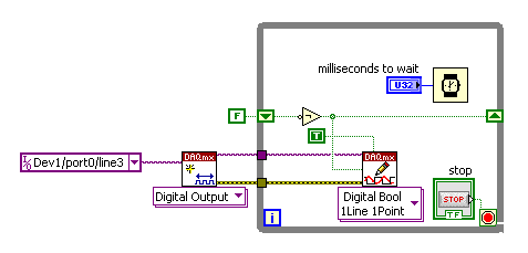
It's the vi, I did to generate the digital signal of frequency with MyDAQ. Any suggestions on how to do this if the following is false, would be great too, as I just got the MyDAQ a few days ago. I think there must be a better way, but it's the best I could come up with so far.
Hi Jonny,
The General logic, that you use to create a digital pulse train is very good. This VI you wrote should work and create the pulse train based on timing of software (which is fine because you have not DIO clocked by the material on the myDAQ anyway). However, it is generally advised to start the DAQmx task just before your time loop and then disable the task after the while loop when you press stop.
For reference, there are a few examples of good enough LV that I recommend you watch too much for this application. If you try just to create a digital pulse train, the example Gen dig Pulse Train - Continuous.vi is a good example that uses a counter to create a digital pulse of your desired frequency train. It is generally the preferred method to create a pulse train, if you have equipment available to do (the myDAQ there a meter). Otherwise, there are a few examples DIO who write continuously in a digital line / port.
If you are unfamiliar, you can find the examples by clicking Help > examples find... into LV then navigate to hardware input and output > DAQmx > generating digital impulses or the digital generation.
Also, here is some additional information on the myDAQ and its counters:
Hope this helps.
Chris G
-
Frequency of signal and pulse duration varying as to reduce the duty cycle
To sum up my problem, I am creating a period and the controlled voltage pulse sequence, but as I decrease my cyclical report, the distance between each pulse begins to become irregular. More precisely:
I want to have three pulses, each a positive amplitude specified, long, with 23 ms between each 80 microseconds. After these three impulses, I would have a negative pulse of 3 * than amplitude, followed again by Ms. 23 this cycle must be repeated 260 times.
I tried first of all to create the positive impulses to help simulate Signal VI, assigning a square wave with a frequency of 43.327556, an offset of 0.5 and the amplitude of 0.5. And the operating cycle as the default value of 50%, the signal seems to be normal (constant frequency and the duration of each pulse is equal;) "I'm in a position with an oscilloscope). However, when you set the duty cycle for. 3466%, the time between each pulse varies and some legumes are longer than others. I wrote the data able to file directly from fake Signal VI to ensure that he was not only a problem of scope, but it seemed that writing to a file of measure has not sample enough points for me to accurately measure. Even decrease the market barely 10% factor, I see the question arise already.
So my question is, I'm doing something wrong here? It is a kind offset of Labview to try to perform a duty cycle that small? And are there any alternatives to the way I have this set up? I thought I would try to use a train of pulses instead, but I'm not very familiar with this and I know, you can't control the amplitude of the pulses.
Any help is appreciated! Thank you very much.
My guess is that you are limited by the sample rate. If the difference between the two signals time is less than the sampling period (1 frequency / sampling), you will not be able to generate the signals you want.
Please tell us the sampling rate, you use and the settings that work and those that do not. If your data file is not too big, please post so that we can see some data. Post your VI can help too. Check the default settings before you save the VI.
Lynn
-
generation of digital, analog signals read snap SMU-6358
I have two SMU-6358 card and I want to send control signals to my camera and read the analog signals from the device with them.
For the digital control signals, I tried to set up a system where I specify the identifiers of the pins, bring them into arrays of strings - the respective waveforms would be collected in the tables too - and I transfer them to a VI of inputs/outputs multiples that puts digital waveforms for the cards output pins.
I developed this code here, but it doesn't seem to work. I can't understand how I can convert the string and form table wave to meet the requirements of the input/output VI or which another VI I could use to do the job. Or is there a smarter way to do it?
Thank you
Kriváň
Dear Kriváň
Please find attached the VI in LV 8.6 format. Also, I HIGHLY recommend to rearrange the front panel and which makes it neater, your code is very hard to read and not structured at all. I hope this helps!
-
Error to find the frequency of signal to tachometer
I use the vi "Extract only your Information" to find the speed of a motor. The entrance is a monarch Laser Tach AC output. Tach reading is very regular and the AC output is 5 volts peak. There are a few negative pics, but these are at the speed of the engine. My output frequency, who should read the changes back from 1800 1800 at a frequency near 5400, but not exactly 5400 (5321, etc.). Y does it have no signal conditioning that I'm missing before signal to the vi "extract", for example, the window it and then use the frequency domain cutting-edge research?
Thanks in advance,
Ron
Matt,
Just to let you know that I put a bandpass filter in my vi. I took the input of the speed estimated of the user and put in parentheses of the bandpass filter to be 25% below 25% above the target and the input of speed tachometer works very well!
Ron
-
Generation of pulse type signals cannot be done. Help. Please, I beg you.
How can I generate a computer signal in labview software but using is no DAQ?
I need a continuous impulse which is essentially increasing and decreasing slowly WRT time. i.e. it is a pulse, it is already given in labview simulate signal option. I need the DC signal which can be will be the merger of more than 2-3 signals. Please help me with the solution, if possible, or any solution as soon as possible.The image of the pulse is attached.
The link of the pulse is: file:///C:/Users/Priyabrata%20Saha/Desktop/internship/pulse.JPG
Have you tried "simulate arbitrary signals"?
-
200560 error during the generation of the two signals of AO
Hello
I am trying to send out two signals and I get error 200560 to "wait until done" vi.
I was wondering if there is no solution for this problem.
BTW, the vi is attached.
Thank you
Pooya
You have your clock set to continuous samples. I don't know if you can use 'Wait until what' If you the task will never happen. Set your click on over and see what happens.
-
Hello
We need power RF amplifier with a function generator to create plasma in an ion source. The signal pulse duration must be 1ms long, repeated twice per second.
Today, we work in the following way: we spend the RF with f0 (aprox 1,995 MHz) frequency. After 20, we send a trigger signal passing frequency f1 (aprox 2.005 MHz). We keep this frequency for the rest of the pulse. However, the plasma that we generate is not 'constant' or stable during the whole impulse. If we smoothly change the frequency during the pulse we could improve.
We would like to do: use the frequency sweep: rather than use this frequency hopping, we would like to move smoothly f0 f1 (frequency scanning). Then F1 to f2.
As we have a PXI for data analysis, we believe using the arbitrary function generator of NOR: 5406 of NEITHER allowing the frequency sweep. However, in the book loads, it is not very clear, and I have a few questions:
-We can create a "list of frequencies. In the site OR below, it shows that the "minimum of Step' is 1.28us, which would be ok for us (I understand that the"minimum duration of Step"is the minimum time between 2 frequencies). However, the manual of the device "NI PXI/PCI-5402/5406 specifications" said the frequency list has a time step of 1 ms to 21s. What is the good?
-It is also said that the "duration of minimum list" is 1 s. For us, need us a shorter list that 0.5 seconds (we need to repeat the same pulse twice per second.). Is it possible to do what we want?
-At the end of the day, we would like to implement a control loop which modifies the list of frequencies in real-time.
http://zone.NI.com/reference/en-XX/help/370524L-01/nisignal_generators_help/features_by_device_smc/
Thanks for your help.
Best regards
Jose.Hi Jose,
You're right about the inconsistencies of the documentation. The minimum step was of 1 ms, but was changed to 1.28 µs to driver version 2.6. The help document has been modified to reflect that, but the specifications were not. I'll make sure that attaches.
The length of the minimum list is not listed in the book loads, and the latest version of the help the signal generators OR (driver version 2.9) lists the minimum list than the 1 step length. Aid has changed to the driver version 2.6.1 to clarify that the 1s meant 1 step. I've attached a screenshot of the help of the most recent.
There is an example that is installed with the NOR-FGEN driver called "Fgen Sweep Generator.vi". I would recommend from this for your application.
I hope that some of the inconsistencies in our documentation brightened. Please let us know if you have any other questions.
Elizabeth K.
Generators of signal produced technical support engineer
-
Analysis of frequency common time in Signal Express?
Is it possible to do joint analysis frequency time Signal express? I don't see in the section "analysis", so I guess that it is a separate tool that should be added, if possible still Signal Express. Help?
SignalExpress does not natively support joint time frequency analysis. However, check out the Sound and Vibration toolkit that expands the SignalExpress. It can do what you want.
-
Bluetooth tends to disrupt the WLAN Signal in practice?
I know that Bluetooth and W - LAN, both running on the same band of signal, technically speaking, I guess you expect to disrupt each other, but I think to put a bluetooth mouse to use with the bluetooth on my laptop and so will use both Bluetooth and W - LAN whole, constantly.
Someone else did this, and you have problems with it?
Thanks in advance, Jack...
It's a problem of the first versions of material Bluetooth (Bluetooth 1.0 and 1.1). If your Bluetooth hardware is newer for example not longer than 4 years, then it shouldn't be a problem to use Bluetooth and Wlan at the same time. The specification of the bluetooth Bluetooth 1.2 material a mechanismn call "Adaptive Frequency Hopping" (AFH), which avoids interference between WLAN and bluetooth. If you are not sure if your material is new enough to check it out, visit the following Web site:
http://APS2.toshiba-tro.de/Bluetooth/?page=Toshiba/internal-BT-module -
niUSRP Signal.vi set not allowed inside loops?
It seems that niUSRP than signal.VI set is not allowed in loops. After the decision of the VI, I get this message:
niUSRP configure Signal.vi
, this attribute cannot be changed while the driver is in the operating state. Is there a way to change the frequency of the carrier, while the driver is running? With the help of property Node.vi of niUSRP to set a new frequency within a loop is also not working. My goal is to create with the USRP to frequency hopping.
Hi YYY.
Thanks for your VI, including in the post. I was able to download it and reproduce what you see. There are a few things that need to be changed in order to get this to work.
First of all, you don't need to have the niUSRP function to configure Signal.vi inside your time loop. You can put this outside the loop and a property node allows you to change the frequency with a property node. You already have the property node in your code, you just need to change it to write instead of read. There is an example that will do just that, if you just want to use it instead of modify your code too much. It's called niUSRP EX Tx continuous Async Reconfig on the Fly.vi.
Then, the reason why you are not able to go at the rate of 1 ms/s IQ with the code you have is because you're trying to read and write the frequency during each iteration of the loop. Because of the time to query the hardware, set the frequency and read the return frequency, the I was able to get the maximum rate of IQ was around 500kS/s. This is due to a combination of hardware and driver limitations. Even with the example above uses the property instead of the function of the configuration node, if I put in an indicator to look at frequency I can't use a faster speed of the IQ.
Try to change the property node and the withdrawal of this indicator, you should have a lot more success. Let me know if this does not work for you or if you have any other questions, I'd be happy to help you.
-
Square wave generation phase offset problems using PXI6602
Hello
I'm generating 2 signals using an incremental encoder AB using a PXI6602 to simunlating.
Signals must be offset square wave, 34,133 Khz, by 90 degrees, which I'll put dividing (1/frequency) into 4 and put the result in the knot of late initial .vi DAQmx create channel (frequency impulse Co generation).
Resulting signals phase difference however does not consistantly measures 90 degrees. 1 in 5 rounds of the vi has at least a matter of resulting in a test phase angle has failed.
Can someone suggest a stable solution for this.
Thank you
David
John_P1,
After posting the previous comment, I went back to play some more with him, and he now runs and returns a positive result every time.
The change that has had the desired effect was for the type of trigger that I had selected (Advance Digital Edge). Change this to start digital dashboard whose value fall of dash, the error disappeared.
Feel free to always criticize the vi and suggest / modify to improve stability / efficiency.
All feedback is voluntarily accepted

Thank you
David.
-
Frequency Modulation thing. How to solve it?
Hello!
I have a VI that is frequency modulation using two nodes of formula. A node is for the generation of Message signals and the second node form - generation of FM resulting. Equations of observation of FM, the position within the equations of FM - should be instegrated and FM is like:
FM (t) = A * cos (2 * pi * Fc + 2 * pi * D * Integral (shrub);)
, where A - amplitude; PI - 3,14; CF - carrier, shrub - message signal frequency; D - frequency deviation.
That's why I use external integration, then pass signals integrated into the equation of the FM.
The problem is - Signal has very low voltage (amplitude) after integration - and it no longer works.
Should I multiply signals part until it is the same amplitude as the original signal?
What could I have done wrong here?
Thanks in advance.
I created a polymorphic VI 'Generation FM'. This frequency-modulated signal output generates VI according to wired signal Message. Generation VI FM accepts two types of Message report entered - waveform or a table. If you wire up a table for Message intput - you will also need to "Sampling frequency" input wire. Now everyone can put this polymorphic function on their pallet pattern and use it.
Note: You need to put on a VI block diagram called "FM Generation.vi", two other files ".vi generation FM (table)" and "Generation FM (waveform) .vi" are instances of function that are responsible for entries or entry level waveform.
This feature is designed for LabView 7.1 or higher.
Do not hesitate to write feedback.
-
Tecra M6-EZ6612: Bluetooth and WLan operate at the same radio frequency range
Hi all
I have a laptop that is Tecra M6-EZ6612...
I have a problem that when I install the bluetooth I have a massege indicating a conflict between the wireless and bluetooth...Two of them are working in the same radio frequency range!
So, I wonder how I can change the frequency range of the bluetooth device? !!!Not like about it. Material Bluetooth v1.2 or v2.0 have included technology called AFH = "Adaptive Frequency Hopping" that tries to avoid conflict with WLAN. It can only be a problem if you have a very old hardware BT (before 2004).
-
Hello
I want to do a continuous waveform. There are samples and files online to do it, but I would like to be able to change the frequency of signals continuously, I mean something like a function generator. I try to use the channel of PFI in NI 6221, but it provides just the waveform with a constant frequency. I wonder if it's a good idea to use the channel of the IFP? I want to give 100 kHz square wave.
Thank you
Hi Saridar
Thisexample may be what you are looking for!
Concerning
Maybe you are looking for
-
How to share a contact in the address book by e-mail?
I am trying to send email coordinated in a mailing list of my address book to a colleague. I have tried to go to the option of attachment but does not include the option to contact address book. Also tried to copy what I can paste into the body of th
-
Hi, really of struggling to find an answer to this on the HP website. I'm trying to know if HP to perform benchmarking third-party software services running on HP hardware? Background is that I work for a company IT Council and we have developed a s
-
Update Firefox 6.0 is useless to me because many websites I visit are not displayed properly, I guess because the Java modules are disabled because of incompatibility. They appear correctly in Internet Explorer. In addition, the add-on from Trend Mic
-
Satellite M70 - after HARD drive partitioned, the OS does not start
Hello Good then this is a real doozy, and I hope that someone will help. I started to fix my satellite m70 girlfriends using the disc of recovery etc, everything went fantastic, the HARD disk has been erased and Windows + all software has been reinst
-
Hi all... I had a problem when I select the menu (data acquisition), the program as being stuck. What my error? Can someone help me? Sasha all