Generation of SPI by using the b PCIe-6535
Hello
I have a data ready signal generated every 100uS or so by a SPINNAKER of slaves.
The SPI master must generate then 96 SPI clocks anhd captures data returned.
The process is repeated every 100uS. The SPI 96 clocks must be completed before the next event, hence the need for an ardware or RT system.
Would it not possible to program the PCIe-6535 b to act as the master of SPI that is to generate the clocks, store data, such as a Windows LabView program can probably pick up data without loss?
Or I'm looking for something more like a RIO?
References & code examples would be great!
Tags: NI Hardware
Similar Questions
-
Writing to SPI peripheral using the NI PCIe-6363
I'm writing a labview program to write to a simple SPI device using the DAQmx 6363. I found a library and examples of code and started using the "SPI - internal Clock.vi DAQmx".
http://www.NI.com/example/31200/en/
I believe that this is the right place to start, but I keep coming across mistakes that I can't locate.
200452 error occurred to the property Node DAQmx export Signal (arg 1) in Init IntClk Device.vi-> DAQmx SPI - internal Clock.vi
Possible reasons:
The specified property is not supported by the device or is not applicable to the task.
Property: DataActiveEvent.OutputTerm
Task name: _unnamedTask<18>
I found the vi the cause of the problem, but I'm not sure what the problem is yet. Any help is appreciated.
I believe that this knowledge base article contains the answer to your question. Follow the steps in knowledge base article to determine if the property node that you are using is supported by your card.
-
Why are the characters sets are getting deleted using the card PCIe-1433?
Hello
I have several framegrabbers PCIe-1433 in my possession and I have a routine that sends out packets of 1 KB of calibration data to a camera at a time package. Usually after a few starts, a time-out error because not enough data is received by the camera (the camera reacts returns with a character of receipt of each whole package). The strange thing is that the same code works fine on the other boards of framegrabber no 1433 (using framegrabbers 1428-PCI and PCIe-1429, although I'm not able to take advantage of the faster transfer speeds) on this computer.
I think the problem is the use of framegrabber PCIe-1433 AND model of the computer. I tried the same code on two Dell Precision T3500 and they both allow only a few packages to send before that happen a transmission error. When I try the same code and the same jury 1433 on a Dell Precision T3400 code works fine and I am able to send 1000 a lot of packages to the camera without error.
It can be the cause of this problem? I tried to change the cameralink cables and had the same problem.
Thank you
Bruce
-
State ban of the NI PCIe-6535 b
Hello
I make sure that my PCIe-6535 b never down all active lines at the same time, not even in the transient state or power up/down. This means hardware failure that this control panel.
Is there a setting I can put this advice to make sure that this will be the case?
Is there a "prohibited" State that I can configure?
Dear Pawel
6535 b, behavior at the start of each line is software-configurable, can be set to three States, 0V, under 2, 5V or 3, 3V. For normal operation, please make sure that the lines are in the correct state of the software. The best way in my opinion is to build an API that always performs a check of the other lines before defining an active line, then use the card only through the API. (If there are other users, you can lock to prevent overrriding audits)
If the safty software is not applicable in your case (for example, you want to use maximum speeds possible, so there is no time for the controls, or do you need a more secure evem solution) I sugest an e minor addition.
Kind regards:
-
How to record video using the NI PCI-1411?
Hi all
I have an old NI PCI-1411 Pulnix camera, LabVIEW 7.1.1 and Module NI Vision Development 7.1.0.
What I want to do is to simply record a video, and I can't find any tools to do so.
I found an example in the code LV to save the view, but it seems to be too slow to save all frames.
Am I missing something?
Thank you
Jakub
Hi Jakub,
There is nothing that directly records because I think that you are eager to reach. To save an image video, you will need to use a write function, to get the data and then save it to a file, some functions also have a read function.
I suggest that you look at the function reference manual and available in IMAQ, LabVIEW help files and they are also available on our website.
I found an article that uses a good architecture which may help you to structure your application, for what I understand, that you are eager to make you you will need to make emissions to get the IMAQ camera data into a buffer to save.
There are also examples available from the example finder LabVIEW avi in the help tab that are a good reference in the development of any application.
If you have any other questions please ask.
Thank you
-
Using the Interface of FPGA functions palette
Hello
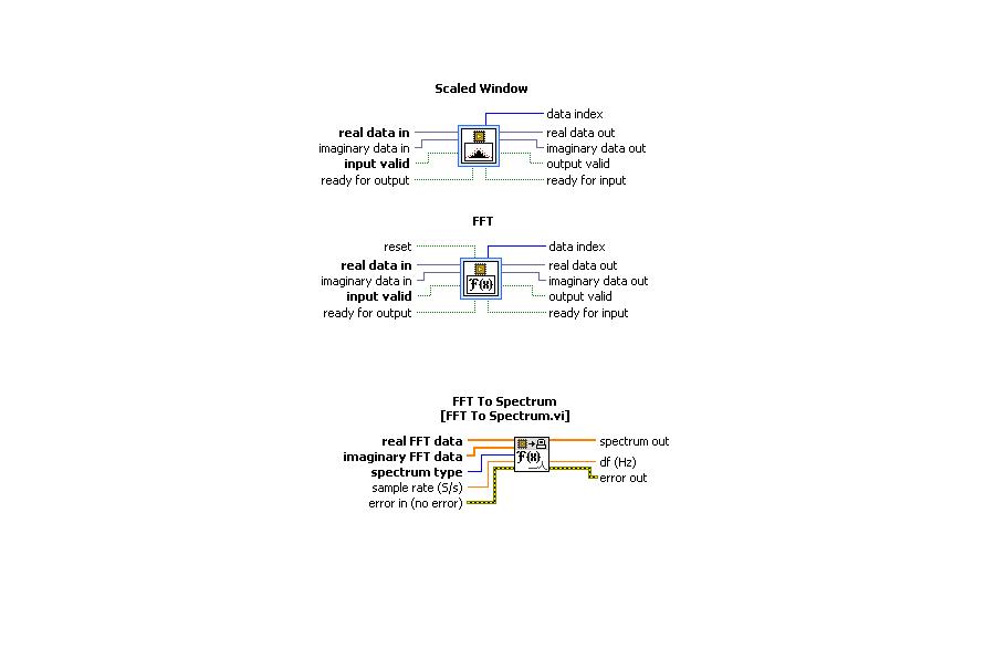
I use the card PCI-5640R and PXI-5600. I want to use the "scale" and "FFT" exspress screws to the range of functions 'Mathematical FPGA and analysis' in my VI "FPGA VI" and "FFT spectrum for '"FPGA interface"in my"host VI.
A poster of the code examples in which these three subVIs are used can.
Thanks in advance.
Kind regards
Rashid
The answer to this question is available to
-
Hello:
I use the card PCI-6602 and am a bit new to the use of timer/counters. I use the Commission to measure the position of a quadrature encoder.
I would use the time base internal 80 Mhz the map of 6602, but examples of LabVIEW will not allow that. In the example, he States:
2. call the DAQmx Schedule VI (sample clock) to configure settings of clock synchronization external sample Mode Sample and sample clock Source. The sample clock Source will determine when a sample will be inserted into the buffer. The 100 kHz, 20 MHz and 80 MHz time bases can serve as the sample clock Source. The Edge parameter can be used to determine when a sample is taken.
Is it possible to use the database internal time for my application?
I have attached the example vi that I use.
Thank you.
Pat
Hi, Pat.
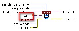
The rate determines how fast the samples are acquired and put on the material buffer. This value depends on the basis of time, which is specified by the source of the VI DAQmx calendar entry. The default source on the PCI-6602 map is the on-board clock (80 MHz). The rate must be a divisor of the source. For example, 80 MHz, 40 MHz, 20 MHz, 10 MHz,..., would be acceptable values for the entry rate.
So the answer to your question would be to remove the entry from the source and ensure that the rate is a factor of the source. Leaving this entry unwired will use the clock shipped by default of the unit, as shown in the screenshot below:
I hope this helps.

-
Is connected to the Internet, but cannot use the Compaq Presario SR5123WM desktop PC
Product name & #: Compaq Presario SR5123WM desktop PC (GC660AA-ABA)
Operating system: Windows Vista Home Premium 32
No only error message when Internet Explorer does not display the page or iTunes can't find any connection network (any application that requires an Internet connection).No changes were made to the system.
I have the dial-up connection. The Bureau uses the Modem - PCI Soft Data Fax Modem with SmartCP (COM3).
Once I start the computer, log in to my user and connect to the Internet, I click on Internet Explorer and type in Google to see if it would work. It is said that "Internet Explorer cannot display the webpage". For iTunes, he would say "iTunes has not to connect to the iTunes Store." Make sure your network connection is active and try again. »
I tried all solutions online and by phone. I reset netsh int ip / winsock. I reset Internet Explorer options. Nothing works.
What is strange, is that the Internet connection works well on my laptop (using Conexant D110 MDC V.92 Modem (COM3)).
It would be GREAT if you could help me find a solution to this problem, because this has happened for months, and I'm tired of waiting. I put all my hopes on you.
You may be able to do a system restore if the original HP partition is always on the computer.
Here is a document detailing the steps:
-
synchronization of several b PCIe-6535
Hello
I need to synchronize all designated offices in four of the b PCIe-6535. They are all connected to the cable RTSI, operating at 5 MHz sampling rate.
All 128 lines must begin to display the data when a single PFI trigger is received.
What would be the best way to synchronize these four devices? The examples NOR see the concept of master/slave, but is possible better? I would like to see all four volumes in the form of an array of 128 channels.
Can I combine all the lines in a single task and write the data to each of them at the same time?
Thank you
Dear Pawel
You can use the RTSI7 line for distributing clock signals (/ SampleClock, specifically). The trigger signal can also be distributed by the RTSI. For routing all available, you can check the routes tab device in MAX. I have also experimented with this array type DAQmx configuration, please find the fixed results.
Let me know if you have any other questions.
Kind regards:
-
OR PCI-6542: Creation of dynamic waveforms using the HSDIO library
Hello!
I have problems to understand how to create waveforms using the HSDIO library to run on a card PCI-6542. I need to create a program that activates a channel for 12.5 microseconds, waiting for a while (i.e. 100 samples) and activates another channel to 12.5 microseconds.
This program must be used in a Multielement ultrasound system.
Here the example of dynamic generation program that transforms the channels 0-2 on 1024 samples.
/************************************************************************
*
* Example program:
* DynamicGeneration.c
*
* Description:
* Generates a simple model on the specified channel.
*
* Pin connection information:
* None.
*
************************************************************************// * Includes * /.
#include "niHSDIO.h"./ * Sets * /.
#define WAVEFORM_SIZE 1024int main (void)
{
ViRsrc deviceID = 'Dev1 ';
ViConstString channelList = "0-2";
ViReal64 sampleClockRate = 50.0e6;
DataWidth ViInt32 = 4;ViUInt32 waveformDataU32 [WAVEFORM_SIZE];
ViConstString waveformName = "myWfm";
ViInt32 timeout = 10000; / * milliseconds * /.ViSession vi = VI_NULL;
Error ViStatus = VI_SUCCESS;
Bruno errDesc [1024];
ViInt32 i;/ * Initialize generation session * /.
checkErr (niHSDIO_InitGenerationSession)
Deviceid, VI_FALSE, VI_FALSE, VI_NULL, &vi));/ * Assign channels for dynamic generation * /.
checkErr (niHSDIO_AssignDynamicChannels (vi, channelList));/ * Set up the clock sample parameters * /.
checkErr (niHSDIO_ConfigureSampleClock)
VI, NIHSDIO_VAL_ON_BOARD_CLOCK_STR, sampleClockRate));/ * Query the data Width attribute * /.
checkErr (niHSDIO_GetAttributeViInt32)
VI, VI_NULL, NIHSDIO_ATTR_DATA_WIDTH, & dataWidth));
/ * Fill the waveform with ramp data * /.
< waveform_size;="">
{
waveformDataU32 [i] = i;
}checkErr (niHSDIO_WriteNamedWaveformU32)
VI, waveformName, WAVEFORM_SIZE, waveformDataU32));/ * Start the generation * /.
checkErr (niHSDIO_Initiate (vi));/ * Wait for all the generation * /.
checkErr (niHSDIO_WaitUntilDone (vi, timeout));Error:
If (error is VI_SUCCESS)
{
/ * Print result * /.
printf ("made without error. \n") ;
}
on the other
{
/ * Get the description of the error and print * /.
niHSDIO_GetError (vi, & error, sizeof (errDesc) /sizeof (petitioner), errDesc);printf ("\nError encountered\n===\n%s\n", errDesc);
}/ * log * /.
niHSDIO_close (vi);/ * prompt to go out (for the popup console windows) * /.
to continue...\n");
GetChar ();error return;
}Issues related to the:
How can I change the values in waveformDataU32 to create market reports (instead of just always on)?
How to select the channel waveformDataU32 is applied to the?
Thank you!
Zachary Geier
The waveformDataU32 table is an array of 32-bit integers. Each bit corresponds to a line on the device. On the first clock cycle, this program outputs:
0000 0000 0000 0000 0000 0000 0000 0000
Then it displays the following, changing at each clock Pulse:
0000 0000 0000 0000 0000 0000 0000 0001,
0000 0000 0000 0000 0000 0000 0000 0010,
...
and so on all the way up to 1023:
0000 0000 0000 0000 00000011 1111 1111
In the example that you include at the bottom, you set the least significant bit (LSB) to zero and one, actually only change one line on the output. To change all the lines, you must instead use 4 294 967 295 or 0xFFFFFFFF:
< waveform_size;="">

     < 200){="" if="" sample="" number="" is="" less="" than="">

          waveformDataU32 [i] = 0;     Disable channels 0-2

     }

     else {}

          waveformDataU32 [i] = 4 294 967 295;     Otherwise turn on all channels to 800 samples

     }

} -
My problem is that I bought apple tv 4th generation of the United States. now I want to use it in India, where it is common to 220 volts, but in the United States, it is common to 110 volts. Can I use the apple tv in India?
BBought Apple TV USA for my children in Europe (220V).
No problem, just replaced the plug
-
Read only the SPI using the box USB-8451
I am using the NI USB-8451 box to read the SPI of a Honeywell digital pressure transducer data. The difficulty comes from that part of Honeywell uses only the SPI in half-duplex mode, meaning that it only transmits data, but does not require anything beyond the appropriate chip select signal and SCLK to start transmitting its 32-bit sensor data. To facilitate experimentation with the sensor, I bought a USB-8451 SPI Interface thinking I could easily configure the 8451 to read data from the sensor.
However, if I understand the situation, there is a problem. The 8451 considers full duplex data, i.e. a data word must first be sent to the SPI device in question before the unit will start to transmit back data of its own. And since the MOSI data writing periods, since this particular device starts transmitting immediately once a clock is applied, synchronizing the unused address data will cause the unit will return its data before the 8451 begins listening for data in return. The call used by the 8451 to write read action can be divided into the individual reading and actions of writing of any kind that I could discover.
Can someone tell me if I missed something in this operation or if there is some quick tips, that I could use to be able to use the 8451 therefor? Thank you!
Doug G.
Exactly correct. It's nice when things are easier than expected. Hope it works as easy as it sounds.
-
I'm trying to use a NOR-USB-6221 to implement SPI in a C++ application. When I try to configure a digital output task that uses ctr0 as the clock, I get an error stating that 'Sample clock' is not supported and use instead "on demand". I would be able to use the NOR-6221 and if so how to do this? Thank you.
Hi IntAndTest,
Maybe silly question: are you sure that you have a USB-6221 and not a USB-6212? The USB-6221 supports clocked DIO, but the USB-6212 is not working.
A problem with your code: when you specify a terminal DAQmx name, it must be is compared to the device (such as 'Ctr0InternalOutput', "AI/SampleClock" or "PFI0") or contains a slash before the device name (like "/ Dev1/Ctr0InternalOutput", "/ Dev1/AI/SampleClock ', or ' Dev1 / / PFI0"). This does not apply to the names of physical channel (like ' Dev1/port0' or "Dev1/ctr0").
The error is returned from code that you have not displayed? Your says error message DAQmxCreateDIChan failed, but the code you posted does not call this function. In addition, I don't see a call to DAQmxStartTask or DAQmxWriteDigitalU8, U16, U32, whatever.
Also, what NOR-DAQmx version are you using?
Brad
-
How to import pictures in the excel worksheet without using the generation of reports
Dear friends
I want to know how to import the image or the image file in excel worksheet without using the generation of reports...
Please come with suggestions or the code example
Concerning
Knani
Please go through the link below
http://zone.NI.com/DevZone/CDA/EPD/p/ID/3638
Even if a Subvi is absent I think it will be useful for you.
Concerning
Rajesh nawal
-
The second image lost in CAN communication when use card NI PCI-CAN/XS2
I recently had a problem on CAN communication.
I need commmunicate a Cluster with CAN BUS, baud rate is 500 Kbps, the BOX is card NI PCI-CAN/XS2. The operating system is Windows XP.
normally, the PC send a Cluster command, then reread a frame of data of the Cluster, but for some controls, the Cluster will return two data frames, and the program on PC cannot receive the second frame, he lost.
I searched the forum, most of her results is the overflow of CAN BUS error, which make the CAN setting lost, but there is not an error on my program report and baud rate is not that fast, I also use another port of the NI PCI-CAN/XS2 to monitor the bus CAN, the second frame of data never appear When I can replace NI CAN map vector CanCaseXL (CAN card) and call of CanCaseXL DLLS in labVIEW, it can get the second CAN fit, the vector CanCaseXL monitor can get the second image data also.
Yes, is there a software/hardware configuration must be done to get the second block of data?
the attached photos are NOR-CAN/vector ALLOWS to follow and CAN init/write & read in my program.
Any reply is appreciate! Thank you
Hello iwantofly014,
I don't know that the framework is not lost.
Could you post your code? In particular the data Get VI?
Also, can you make an indicator of the output of the ncReadNetMult?
It seems you are trying to implement the UDS and KWP2000 Protocol. Is this possible? We have a product that already implements these two protocols and really simplify this type of application. Its called the Automotive Diagnostic command set.
Have a great day.

Maybe you are looking for
-
HelloI have a laptop of old P750 for 2 months, after they need to do a restore to a disk upward, I now get the above error.I then decided to do a cover of toshiba with a clean install and still get the same result of windows update is not not able to
-
1536 LaserJet MFP: Installing the full driver software for LaserJet 1536 MFP
I've recently updated (?) from Windows 7 to Windows 10. At first, that everything worked well. However, I started to get more notifications and error messages that various HP software or files did not work properly whenever I booted the computer or
-
Bluetooth problems in reception of the archives
I am Brazilian and I posted a question in Portuguese, also. I'll still try to explain in English. Since a few days now, I can not send pictures of my camera EX109 Motorola and the Motorola Xoom Tablet via bluetooth on my laptop ("not sent" as a respo
-
After a fresh install of XP SP3, does not work my previously installed programs. What should do?
Had a problem when the power is gone, just as I have to boot my system. It resulted in a corrupted system file. Tried to fix it by using the original installation of Windows XP SP3 CD, but arrived at a position where Windows wanted my password but th
-
BEFSR41 issue Internet connection
Trying to connect to Cox cable. Installation using "obtain an IP automatically' according to the instructions of Cox. I can read Internet addresses, the IP address, subnet mask, default gateway and DNS on the router status page, but cannot connect