graph timestampo digital and analog mixed
Hola:
Estoy acquired a series of canales analogicos y digitales. MI intention, are representarlos in the grafica (graphic Mixed Signal) misma, pero no encuentro the respond. Editor United Nations VI con lo me gustaria realize.
MUCHAS gracias.
Hello:
I'm acquiring a number of analog and digital channels. I represent the two channels on the same graph (Mixed graphic Signal), but can not find the solution. Joined a VI with what I have.
Thank you very much.
Hi, Carlos
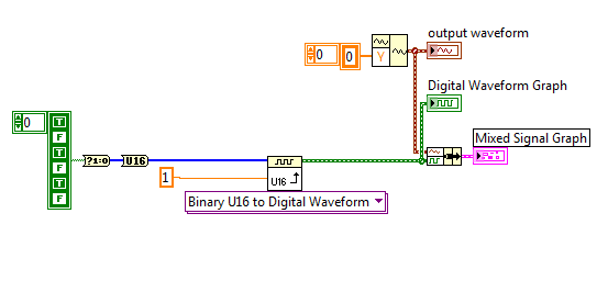
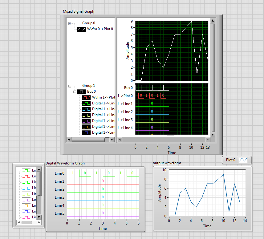
You can implement architecture below, this converts the array to a waveform. Of course if you were after a specific time stamp, then you can use the wave function of construction as well as the function of generation of digital signals. But this should show the basic principle of what you need to see.
See you soon
J
Tags: NI Software
Similar Questions
-
Digital and analog inputs simultaneously - NI USB-6009 and NI USB-6212 - ANSI C
Hello
I'm reading at all times and at the same time analog and digital inputs. Digital and analog samples must be sampled at the same clock and acquisition should be started (triggered?) at the same time (I don't want, after some time, analog reception more digital samples - the opposite is also true).
I found an example (in C source code) "National Instruments\NI-DAQ\Examples\DAQmx ANSI C\Synchronization\Multi-Function\ContAI-Read dig Chan" and tried to run with two USB cards: NI USB-6009 and NI USB-6212. Unfortunately, the two results by mistake, as described below:
DAQmx error: the requested value is not supported for this property value.
Property: DAQmx_SampTimingType
You asked: DAQmx_Val_SampClk
You can select: DAQmx_Val_OnDemandTask name: _unnamedTask<1>
State code:-200077
End of the program, press the Enter key to exit-Is it possible sync analog and digital acquisition in the paintings?
-If so, how?
Thank you
Hello tcbusatta,
Two of these modules, USB = 6008 and USB-6212, support only timed software inputs and digital outputs. This means that you cannot define material timing (like finished sampling or continuous) for these modules. Digital lines can be retrieved or written once to each call DAQmx read.
This means that you will not be able to get any type of synchronization tight between the analogue and digital channels. You will need a Board such as the NI USB-6341 in order to synchronize the AI and DI closely.
-
6009 outputs digital and analog input synchronization
Hello
I work in a program NI 6009. I want to leds by car with outputs digital NI 6009. For example, leads first will be on until what 200 micro seconds then second led will be on up to 200 micro seconds, and then first of all led will be on up to 200 micro seconds. I'll take led with photodedector signals and connect analog output photodedector input NI 6009. I want to synchronize the outputs digital and analog input and separate the first and second led signals the analog input for NI 6009 channel. How can you do with NI 6009? Please ADV
You can not do with the USB-6009 case. Its outputs digital are software with a maximum speed of slightly more than 100 samples per second. The outputs can produce 200 microsecond pulses and cannot be synchronized with the analog input.
You need a device with outputs digital hardware timed or counters that can produce a pulse outputs.
You can synchronize a bit digital output and analog input recording signal on an additional channel to HAVE. Will allow you to see the photodetector and LED the drive with the same schedule and such resolution as described by the sampling rate I. The maximum sampling frequency of AI on the USB-6009 case is 48 kHz that is shared by all channels. If you have two lights to led and photodetector two signals maximum sampling rate would be 48 kHz/4 = 6 kHz which is barely fast enough for your 200 US signals. For more than 4 channels, it won't be fast enough.
I suggest a simple oscillator circuit building and use it to clock a flip flop. This will give you alternating signals to drive the LEDs. You can use a line to reset the flip flop to give you control without the need for high speed.
Lynn
-
Digital and analog gain in Script mode
Hello.
5422 module can change the voltage Vp-p order of 05:54 V.
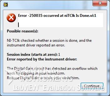
But when I use the property node - digital Gain, after setting the 1.1 V and return to its previous value (V 1.0) occurs the following error:
And when generating a signal of amplitude of 1.1 V signal very distorted.
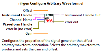
In niFgen configure Arbitrary Waveform VI it is a Gain parameter to control the standard signal (which I understand). Is there something similar for the Script mode?
How to access the analog Gain?
And in general, how to properly use the analog and digital gain in Script mode?
I apologize for possible errors, but the example is not yet complete.
Max O.
Developer of software and engineering,
TeSLa.
Hi max_i,.
Since the ownership of digital Gain help file:
"Specifies a factor by which the digital signal generator multiply data generated before the conversion of an analog signal in the CAD." Saving digital greater than 1.0, the product digital time gain the data generated must be in the range ±1, 0 (assuming that the floating point data). If the product exceeds these limits, the signal generator cuts out the output signal, resulting in an error. »
Digital gain requires the data, being always standard-1 to 1V. The output of 'Ladder' to 'normalise Waveform.vi' here is generally superior to 1, which causes this error 250035. If you search for the property similar to the entry of 'Gain' on the ' configure Arbitrary Waveform.vi ', I advise to use the 'Gain' on the tab 'Arbitrary signals' property in the property node.
Looking at your code, it seems that you try to build pretty standard signals (sine signals). Is that this will change in the future to more complex waveforms? If not, I wouldn't recommend watching one of the examples in the example LabVIEW finder, I find "Sequence of Arb basic Fgen" quite useful. If you want to make scripts as well, I would recommend the example "Fgen Arb Script".
Thank you
David B
National Instruments
Technical sales engineer
-
Digital and analog simultaneous inter channel delay
I need to a simultaneous analog input 1 channel and 1 entered digital who intend to make possible acquisition of maximum speed. Of course I expect no delay channel inter if the two entries on the edge of clock sample even sampling. But this example shows unexpected behavior. Restart acquisition regularly shows different delays inter channel. I hope there is someone there to help out me. See the included example.
I asked the support of National Instruments and they came with an adequate solution.
Time t (0) stamp in the waveform is NOT the start time of the acquisition but it is the time the buffer is read.
To demonstrate this applies the same "pulse train" to the two channels and t (0) all forms of wave at the same time of departure. Observe that the edges of both signals match exactly. Because a single channel is a digital input, we make the logic of levels of tension into account.
Thanks to Henk Talsma
National Instruments
Engineering applications -
Digital and analog generation and acquisition using USB-6251
Hi all
I have to actually synchronize a 6251, USB and USB 6366 Board. I have a vi, which is good that now I am able to use the 6366 as the master and as slave 6251, attached tie. The master generates a digital trigger for (generation synchronization) pulse and the acquisition of the signals on both cards, analog signal ramp and acquires signals. The slave acquires only a series of signals after outbreak.
I want to have the 6251 as master and as slave 6366. The vi attached the other way around as I mentioned above. When I try to use the 6251 as the master, I get an error asking me to specify the clock source (I did the material and some changes in the program as well, as export properly 6251 at 6366 clock).
Thank you
SANJU
Thanks for your reply jonathon,
But in your code below, I coudnt get the Outpput internal PCI-6251/ctrl0...
but I hardwaired the o/p (PFI 12) meter... .and generated a signal meter on this port, I used that as the clock...
Thank you
SANJU
-
Switch between outputs, digital and analog input
Forgive me, I'm sure that there is a simple answer to my problem, but being relatively new to LabView, I do not know how to proceed.
With the help of producer/consumer achitecture I am trying to accomplish the following:
Producer
- Relay nearby
- Read the voltage
Consumer
- Compare the voltage to the expected value and append the true/false value in a table.
It will be run 8 times then wait for input from the user through the dialog box run then 8 times.
My question/problem is how I set up so that the digital analog in and out are timed correctly and get a sample of AI after each relay is closed?
Material used is the cDAQ, (2) NI9481 & NI9221 (1)
Attached, is the vi that I came with this day and a diagram to illustrate the intended application.
Any help is greatly appreciated.
-
Synchronous Digital and analog I/O daqmx
I have 2 PCI - 6254 s in a linux machine and I am trying to sync the analog input (ai0:1) with the incoming digital data (port0) data. I fed a sample
clock to Dev1/PFI0. (I currently use a little the e/s from one of the boards installed) Somehow, I can't align the analog and digital data. I know because I use digital data to reverse the polarity of the analogue data still incoming digital data (print buffer) are correlated with what is happening in the name of the analog data.
If I use the AI/sampleClock internal as the common Terminal analog and digital data seems functional and are repeatable.
Thanks in advance for your suggestions.
The problem is that the two tasks are not guaranteed to start at the same time because they are not sharing a common start trigger. In other words, there will probably be a nondeterministic number of samples of phase difference between the two acquisitions. Unfortunately, the digital I/o on this forum does not support any which trigger feature you can not use just a common starting trigger. Probably the best thing to do in light of what you have described so far is to use PFI0 as the AI sample clock and change the clock for your digital/Dev1/I/SampleClock task. You must then make sure you start your digital task before the task to HAVE it. This should actually slave of your digital clock to the clock of the analog task and actually start both at the same time. Given that each task physically uses a different signal than its clock (PFI0 vs an exported version of AI/SampleClock), there will be a small amount of latency between the two. However, this should be the order of tens of microseconds, so I do not have a significant impact. Also, as the digital task is actually controlled by the clock of the analog task, it will actually start and stop the analog task you called stop task on the digital task. I hope that this will not be a problem for your application.
-
writing digital and analog/PDM
Hi I have a PCIe6351 and try to read a digital port starting with a trigger and activating an analog trigger acquire analog data
is there a way to do it and write a single file in a PDM
in general, this is what I need, but for now I can not write digital TDMS when I try the collapse of the program without error message
Each channel to a TDMS file can have a different data type. What do you mean "the program collapses? Have you tried to write to different groups in the file?
If the data cannot be written to the file at the same time (in other words, if data is written sequentially in the file), you can do with the TDMS recording feature built into DAQmx: http://zone.ni.com/devzone/cda/tut/p/id/9574
-
Windows 7 monitor recognizing as digital and analog
I have Win7 Pro 64 bit, a monitor Acer X 223 and a Radeon 5850 Videocard. I use a single DVI - D cable to the DVI port of the monitor to the video card DVI port.
However, when I go to 'Control the resolution Panel\Appearance and Personalization\Display\Screen' he monitor correctly under the heading display, but it says "(analog)" next to it.
I entered the monitor settings and made sure this 'digital' has been checked and not analog. I've updated to the latest Catalyst drivers. I'm looking for suggestions.
Hi Swede88,
Please see article with some useful information:
http://Windows.Microsoft.com/en-us/Windows-Vista/set-up-a-TV-signal-in-Windows-Media-Center
I hope this helps!
Debra
Microsoft Answers Support Engineer
Visit our Microsoft answers feedback Forum and let us know what you think -
Isolated ground and analog ground in Multisim
What is the availability of isolated or analog grounds in Multisim? Multisim allows 2 main types of designs, standard ground (can also be called grounding, represented always net '0') and digital terrestrial, but sometimes in a design, you will need several references to the ground for the different areas of design, including a ground Earth or chassis point, digital and analog ground terrestrial and sometimes ground isolated.
How that this can be accommodated in a modeling Multisim and the point of view of layout?
Kind regards
Patrick Noonan
Business Development Manager
National Instruments - Electronics Workbench Group
50 market St 1-
South Portland, ME 04106
Phone: 207 892-9130
E-mail: [email protected]Here are examples:
Other reasons Example.ms10 - example of Multisim illustrating how to connect and measure, CGDN, IGND and V_ISO and ALWAYS
Isolated from Source and Earth Example.ms10 - another example showing IGND and V_ISO measured relative to the Earth (0 net)
Special_Gnds.Prz - update database file - creates the new family of "Special_GNDs" (Multisim 10.1)
Thanks to the original user who have requested them.
Kind regards
Patrick Noonan
Business Development Manager
National Instruments - Electronics Workbench Group
50 market St 1-
South Portland, ME 04106
Phone: 207 892-9130
E-mail: [email protected] -
6143 - PCI or PCI-6133: simultaneous reading of analog, digital, and counter
Hello Board,
I want to use a PCI-6143 or 6133 to acquire permanently synchronized values ports analog, digital, and counter on the same device.
I use vb.net to build an application that reads the values of the device buffer and stores them in lists for later use.
By reading some other threads I discovered, that all the S series devices are able to use a source of material for the release of the digital ports.
Here are two among them? What meter ports, they suffer from the same problem?
Software trigger is no option because the sampling rate must be accurate.
Thanks in advance for the answers,
M.B.
Hi M.B.
6143 does not support Correlated DIO (i.e. clocked by the hardware), the 6133 (see-> digital I/o--> Timing). As a result, synchronized doing of entry works with the latter. Acquisition of meter in the buffer is available on both devices. The 6133 also authorizes analog and digital triggering.
To synchronize these tasks, you need to export a clock signal (sample clock HAVE for example) and take to the DIOs and counters for an acquisition in the buffer. An example for synchronization of AI and DI is given once you install the DAQmx driver in the
Please let me know if you need more specific information.
Kind regards
Peter
-
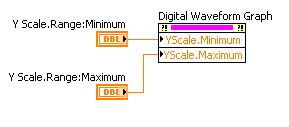
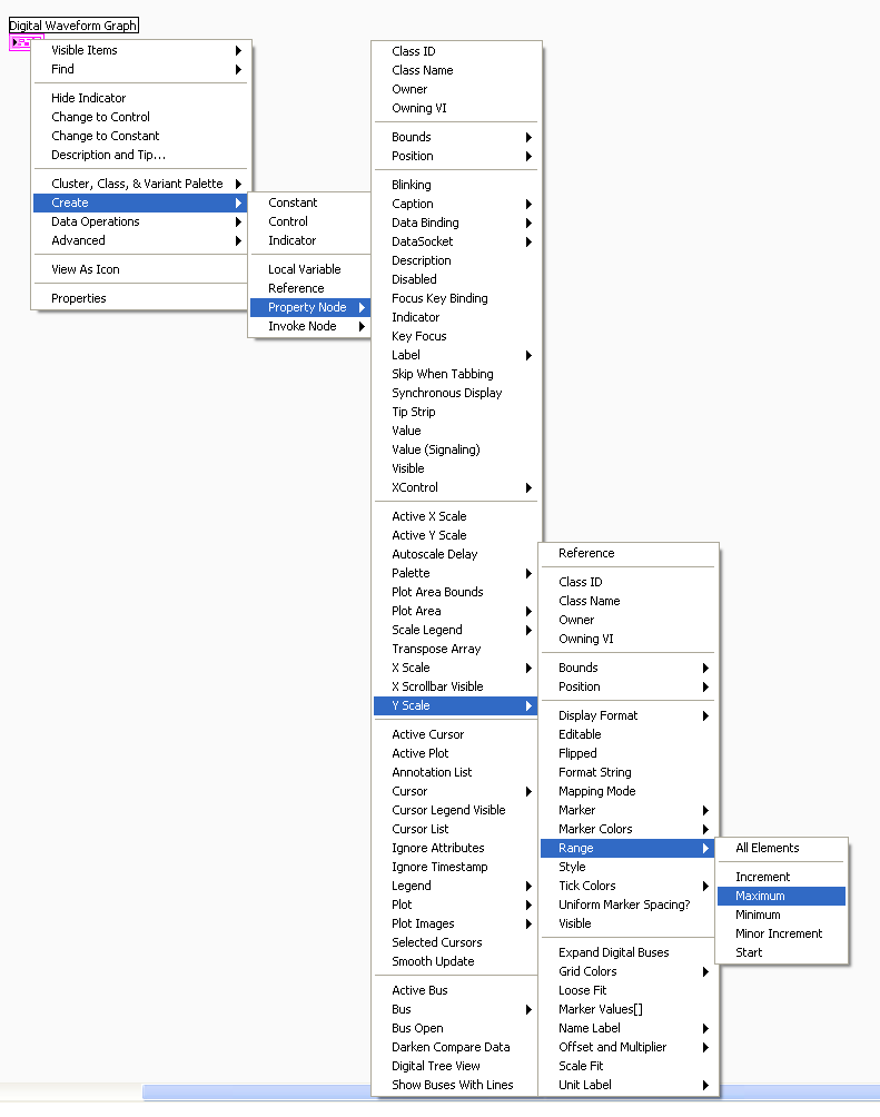
Is it possible to scroll on the y-axis of a graph of digital waveforms?
Hello!
I use LV 8.5.1 and I want to draw 64 signals on a graph of digital waveforms.
But if the graphic is too small, I see not all signals, and if I enable auscale on the Y axis, so the signals are not recognizable.
Is it possible to activate the scrollbars on the y-axis?
Thank you.
Hello!
Try to use the nodes property Y scale with a slider horizontal/digital control. As:
Find it here:
I hope this helps!
-
help understand the digital and graphical waveforms
Can someone explain to me how digital waveform working with NOR?
I did a channel physical and wired to a DAQMx create channel then I have it connected to a NSamp of 1Chan ereading Wfm DAQMx and then wired it to a graph of digital waveforms.
I put digital and graphical digital waveform playback in a loop.
When I run it, it seems to me only to get 1 sample on the graph per loop iteration.
The desired output is to add each digital sample as a function of delay which can connected and or scrolls in time to examine what is happening with the signals.
Where is my mistake?
My VI is attached.
Any help would be greatly appreciated!
Also another quick question, is there a 'comment' as a command / / c or ' in VB? Thank you.
Hi Henry,.
Thanks for the post! It seems that you are having problems with the acquisition and the graphic representation of digital data using DAQmx and LabVIEW. You are right that the type of program you have returned a single sample every loop iteration, because you make an acquisition without buffer, timed by the software. This means that the program reads a sample for each channel, whenever the DAQmx reading VI is called, which will depend on the speed of the software will run. In addition, when you view this data, the chart will only display data acquired for this iteration of the loop (that is, in this case, a single sample).
To accomplish what you want will take some extra work and overhead costs in the software, but you can essentially use a shift register and accumulate samples that your program runs. There is a practice done just VI to do this kind of thing with digital signals and is called DWDT Append Digital Signals.vi (this can be found in the palette of functions in respect of programming"Wfm Digital Waveform"). I created a small example which you should be able to run that does this. What actually happens is that the waveform is rewritten each time with new data added in addition to the data passed in. To be able to scroll back and view this data, I turned off automatic scale on the x axis (if it is enabled, it will constantly increase and tries to show all the data at the same time) and selected just a data window to display. In addition, I added a horizontal scroll bar to scroll through the review data.
And to answer your question about the code comments in LabVIEW, this can be done with a clear Structure of the diagram. You will find this structure in your palette of functions in respect of programming' Structures. Using this structure, you can select a part of your block diagram to disable and switch to the active state of wire through the or add different features that will run. Hope this helps and good luck!
-
BluRay HDMI'd to the TV, TV audio digital-to-analog converter: no audio signal to the receiver
I have a BluRay BDP-3100 connected to the TV via HDMI.
I can hear audio (DVD, Netflix, etc.) very well just the TV speakers.
Have TV audio out audio output digital (optical) > (RCA) digital audio converter > receiver for playing on the sound system.
I get no audio through stereo receiver, DVD or Netflix, only a heartbeat noise. Funny thing is that I can hear YouTube with this configuration only.
All the other audio (cable, Xbox) works very well with TV audio out through receiver converter.
HEY Santa, thank you.
Steve
Try to go to the Audio settings of the Blu - ray player. Replace the Digital Audio output PCM and BD Mix Audio setting to Off.
1. Press button on the supplied remote control.
2. go in settings (toolbox icon) by pressing the left arrow button.
3. press the down arrow button and select Audio settings.
4. Select the Digital Audio output and set it to PCM.
5. Select the Audio BD mixture setting and place it on the off position.
If my post answered your question, please mark it as "accept as a Solution.
Maybe you are looking for
-
How can I remove the automatic log on some sites
I allowed firefox to remember the user name and passwords on some pages. How to 'remember the United Nations' these passwords?
-
Why is there a bar at the bottom of firefox with google, amazon, games, icons etc. on it?
The bar appears on many different web sites, he began to appear toda (January 7, 2013). How can I do doesn't seem not more?
-
How can I remove Yahoo as a search engine for the bad written URL?
I've installed a plugin that put Yahoo as my default search engine.Meanwhile, I could remove most of it and I'm able to use Ixquick again.But when I get a bad URL in the url bar, e. g. motsilla.org, me always looking for Yahoo.How can I remove this?I
-
Source for 2 GB memory for NB100-12 has
Can someone tell me where I can get the upgrade of memory for my NB100-12 2GM has? How much does it cost? To install it, I have to remove renovate 1 GM and replace it with the new memory or what is the procedure?
-
Boolean condition defect Xcontrol
I did an XControl. The ability of the State contains 3 Boolean values among other values. One of the Boolean values, one I've defined, giving. Even if I put it right and select 'make default current value' then 'Apply Changes' and then 'save', I c