HIGH FREQUENCY OSCILLATOR circuit
I need to generate barcodes random using a timer 555 operating at high frequency and connected to a pair of JK Flip flops of installation as a 2-bit counter. May I ask is my correct circuit?
You answered your own question. If you try to run it outside its maximum frequency, you may have irregular gusts. For reliable operation, use the 555 (or no matter which component) in the specifications. If you need a higher frequency, you need a different design.
Tags: NI Software
Similar Questions
-
REGZA 40 "LCD TV emits noise high frequency
A few months ago, I was lucky to win this TV, a 106 cm LCD Regza HD display.
I was very happy because I could never afford it myself, and I am very happy with its performance in general.I found however is that it emits a high frequency noise that triggers tinnitus in my hearing. (For tinnitus are a squeaking noise acute heard by people who have damaged their ears, sometimes called ringing in the ears).
I guess that my hearing is already sensitive listening to lots of live music over the years, but I think that this noise is excessive.
I think that a monitor of this size is by using a good amount of power and maybe feeding could be too work itself.The monitor makes this noise at a constant level even before the start of the sound of the TV show.
I'm curious to know what the suggestion forum users to reduce the background noise?The monitor is still under warranty because it is only 6 months old.
I wanted to be prepared to discuss with the Toshiba warranty people if the forum users can suggest, first, what could be the cause of noise and on the other hand, the possible ways to address the issue.Thank you petekey4
Hello Pete
As you can see it's Toshiba computer forum and I do not think you will find a lot of people here who want to discuss LCD Toshiba TV.
In any case, if the TV is new and with valid warranty the best option for you is to contact the service people and let check your new TV. -
Satellite R630-145 - high frequency beep
Hello!
I'm of the Russia. Excuse me for my English. I have a problem. My laptop beeps. High-frequency sound (noise) breaks out of aperture for fees. When the portable computer fresh tone gets stronger.
How it can be fixed? Is it a serious problem?
Help me please.
Hello
Can you please explain what more this question beep?
When your laptop begins to emit beeps and what exactly happens? -
Re: Satellite R630-130 - silent high frequency squeak
I have Satellite R630-130
I hear a grinding of high-frequency quiet boring when I put any device in USB (mouse, for example).
The location of Squeak is the "caps lock" key
When CPU loading more than 50% or I'm in the BIOS the squeaking is disappears.How to cure that?
Hello
Hmmm, I read about a very similar problem in this forum and only the update of the BIOS might help.
http://forums.computers.Toshiba-Europe.com/forums/thread.jspa?threadID=52506&start=0&TSTART=0The same high pitch noise was noticed and discussed in the thread above.
It was related to the frequency of the processor (C4 noise) or something -
Portege R700-172 high frequency twittering
Hello
anyone experienced a high frequency of the Portege chirping. I admit just a few days. Twice I had such a sound and wonder what it is (it is not the typical fan noise.)? I disabled speakers, but this wans't ' the source of it t...It will be difficult to address this issue on the forum.
Look closely at what will happen in the future, and if this keeps happening again and again I recommend you contact the nearest Toshiba service provider and ask for help.
In general your Portege should bring up some strange noises. -
Hi people,
I have a challenge I'd like to discuss with you and hope to have some ideas and maybe a solution.
I have a systems acquisition (DAQ) Multifunction National Instruments NOR-PCIe-6353 means X-Series!
I would like to generate and measure signals pulse width modulation .
DRIVER:
OUTPUT:
FREQ: 0, 1 Hz - 1 MHz
Duty: 1-99%
Change the setting on the fly
(This works very well and is implemented)
ENTRY:
FREQ: 0.1 Hz - 40 kHz
Duty: 1-99%
Method of measurement: period of semi / ContinuousSamples / AsyncCallback
Here, I have problems I am running only on an Intel Core 2 Duo CPU E8500 @ 3, 16GHz.
And I want to run 2 PWM_IN and PWM_OUT 2
Low frequency work fine!
0.1 Hz - 20 kHz
It is a loopback with
myCounterReader_1.BeginMemoryOptimizedReadMultiSampleDouble (2, myCallback_1, myPWM_IN_1, myPWM_IN_1_Data);
Data = myCounterReader_1.EndMemoryOptimizedReadMultiSampleDouble (ar, on myPWM_IN_1_Data_actualNumberOfSamplesRead);
A higher frequency do not work very well!
20-40 kHz
I get exception Code of State-200279:
Attempted to read samples that are no longer available. The requested sample was already available, but has since been replaced.
Increase in the size of buffer, most frequently the reading of data or by specifying a fixed number of samples to read instead of reading all available samples would correct the problem.
Property: Value of NationalInstruments.DAQmx.DaqStream.ReadRelativeToRequested:
NationalInstruments.DAQmx.ReadRelativeTo.CurrentReadPosition
Property: NationalInstruments.DAQmx.DaqStream.ReadOffsetRequested value: 0
Task name: NI1_PWM_IN_ctr0
State code:-200279
40 kHz, period is 25us = 12, 5 HighTime and 12, 5 LowTime 50% DutyCycle
This means that each 25us I get a reading of 2 samples the HighTime and the LowTime
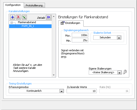
I charge my task of Max, so here's the Setup (sorry its german):
1 can someboby you explain to me what the MemoryOptimized?
2 Zu lesende values means that the size of the buffer 10 is not much but increases the size of the buffer to say 10,000 needing help on
a longer time!
3. playback of data more frequently is not possible because the data are under tension, because it is
4 specify a fixed number of samples I der number is HighTime 2 and LowTime
5. I have does not start and stop the task! Is it better to start and stop the task each time while I still may have a new buffer?
I hope someone has an idea for!
By
Steven
Reading with 50 software we period - bad idea, you will jump impulses. Try to use DAQmx Read Overwrite property, set it to "crush the unread samples" - it will overwrite the impulses without error.
-
6035-E high frequency noise reduces the resolution of 14 bits.
Dear Technical Support Group OR and MF DAQ,
I don't get the complete 16-bit on my DAQ 6035 - E cards and 6034-E resolution because of the high frequency noise.
The Test Panel and the actual catches show 1.2 mV peak-to-peak noise with entries is is failed the GA right input in differential ended mode and single connector - Test Panel screen grab and connector attached picture.
With a range of +-10V, noise LSB + half expected specified in the manual should be only 305 microvolts (20/65536) which is four times less than what I see.
So far, I've been scanning (a channel) to ten times (60 KHz) the rate I need (6 KHz), then SavGol the filtering and sampling downstairs.
The problem is that I need to sweep the four channels that now exceeds the capacity of 200 KHz of the card and also results in huge quantities of useless data.Have considered buying a new USB DAQ with better record, I fear that all products OR suffer the same flaws and gave the purchase.
Please, share your ideas.
Thank you.
GPSman salvation,
Looking at your control panel test plot, it would seem that there is a discrete steps on your axis is between - 0.0019 and - 0.0012 or 700 µV. Then you can see that there is about a little more than 2 discrete steps to your signal, which brings value to about 300 microvolts, exactly as the resolution makes clear.
You can also find that there is a specification of noise and precision in specification. You can find for a single point, the accuracy in the +/-10V between 1,085 millivolt. This is on page 4. This would allow your signal of +/-1 mV of the expected value, the test also indicating panels.
Does that help?
best,
-
given high-frequency sampling one at a time
Hello
I'm using LabView 2011 for resistance measurements. The express vi DAQ assistant is placed in a while loop and it acquires 1 sample (on request).
Each sample is acquired, it is compared to a set point. If the resistance value is greater than the set value, a task is executed. If this is not the case, no action is taken.
Now, I would like to increase the frequency of acquisition of say 5 kHz. As before, I wish the DAQ to give each value because it is acquired and compare it with the desired value. However, only one point acquistion is limited by the speed of the while loop (which does not exceed a few Hz per second when I use the software-timer.) If I use 'continuous samples' at 5 kHz, data acquisition does not give these samples one at a time. It seems to acquire until the buffer is full and then released several samples at a time. It is therefore impossible to compare with the set value.
Is it possible to get data at a high frequency and do compare to the set value, one at a time?
The code is simple enough to do this.
But the problem, it all comes down to how fast all of the other code in the loop takes to run.
The first problem is that you use the DAQ Assistant, which provides a lot of extra load in the loop, especially if you don't set it up properly. (And we can't say because no code is set to look at us.
You should try a real code DAQmx where launch you acquisition continuous samples before the loop, acquire exactly 1 sample in the loop. Then close the DAQmx task once the loop ends. See if keeps.
Why do you need to do this? Note that all instant Windows might decide to fly a second or two and go and do something else like a virus check. If you need at that moment (how exactly do you need that?), then Windows is not the right system for this run.
-
Generate digital waveforms of high frequency
Hi all
I have some problems. Today, I am generating several digital high frequency waves with my DAQ (PCI-6251) card. The duty cycle of the waveform must be adjustable.
The required frequency is 100 kHz.
To do this, I have tried several solutions:
(1) I used counters in the acquisition of data to generate waveforms, and it worked fine. However, I have only two counters. In my application, I need to at least three waveforms with different cyclical report;
(2) I used a 'loop' and structures 'case' in labview to build the model of waveform and then feed them to the digital I/o. However, the problem with this solution is that the frequency of the wave generated cannot be high.
(3) I used a 'digital' generator in Labview to generate waveforms and then feed them to the digital I/o. In this case, the time base is from an external source (200 kHz). However, with this solution, the cycle is not adjustable.
Please give me some advice on how to make these waveforms. Your assistance is appreciated.
OK, so I may be wrong, but after mucking around for a bit, I realized that the regeneration should be automatic - in other words, if you a pattern to the right and then just leave your VI work in a while loop, you will find that the generation is continuous. Discover the correlation dig write metered in the finder for example Labview. You can leverage this as you get the cyclical report you are looking for. You can split the signal down what you write a single period consisting of a series of 0 and 1. In other words, if you want a wave of 100 kHz with a cycle of 20%, you write a pattern of digital waveforms a 1100000000 at the rate of 1 MHz. Using this technique, the resolution of the cycle will be limited by the on-board clock speed (80 MHz = 0.125%).
Let me know if this makes sense - I am unable to reproduce this on my desktop and have never had to do this before.
Cheers, Matt
-
6722 to higher frequencies (about 3.125 kHz)
Hallo,
How can I control the PCI-6722 with higher frequencies about 3.125 kHz? Is it possible to use Labview? How? If it is not possible, how can I control the map to higher frequencies and visualize the information in Labview? I have not found a link to get manuals etc. that help. Links are welcome.
Thank you
Verena
The PCI-6722 does not support the entry of digital waveforms. It's digital lines are static (unbuffered), and every acquisition of waveform of them must be software controlled. Since modern multitasking operating systems are not deterministic, this translates into large amounts of jitter in when samples are collected. If you need good digital waveforms entry, you will need a different card. However, the 6722 has two counters/timers, so if the function you are trying to run is less their capabilities (for example to determine the frequency of a digital input signal), you should be fine. Let us know which task you want to accomplish and we can point you in the right direction.
-
Help the spikes of voltage high frequency Counting
Equipment: NOR USB-6229 (250 ksps / s analog in., 16 bit DAC, 32-bit counters, and internal clocks)<= 80="">
LabView 14
Problem:
I have an experimental app where I need to count the points of tension (entire #) caused by electrons striking a sensor. These tips can be as frequent as 500 000 heads of charge/sec. The tips aren't going to be the same tension every time, but they will be visible above the noise, so I need allow the user to select a threshold voltage that triggers a true count rather than the tips of noise.
Attempts:
To count such a high frequency, I gather that I need to use a counter entry to read fast enough, HOWEVER, I wasn't able to find a way to define a threshold of voltage for a counter entry because I think they expect a TTL signal anyway, which I won't. To set the threshold, I realize reading of analog input can be triggered at a point chosen, which is great, but the Analog Input sampling rate is only 250 kech. / who will not catch count each in my project.
I have a program that uses the channel count edges and it is accurate to 3% of the # expected charges. I was looking at him just with a function generator and the program does not count unless the signal voltage is higher than V 2-3 who does not work for my application. I'll post what I have. Someone know how to trigger at certain levels of tension using counters, or know a way to filter through the noise to get real tips?
Thank you!
You will need a device with a sampling rate of greater than 1 MHz analog input or you will need an external reference. With the external comparator, you can use output to set the threshold, although the user would not be able to see the signal or the threshold, only the analog account result.
Lynn
-
SQL help, how to group in column A and then get a higher frequency in column B?
Assuming that the following table, operation represents each type of operation of transaction
Employee table operation another column c
' < ' id1
' < ' id1
' < ' id2
' *' id3
id1 ' / '.
question, for each operation, which employee do the most? which employee do the 2nd most?
I thought I need to group by operation first, then get the frequency of the employee and get top 1, or at the top of page 2 of higher frequency.
But I'm struct and don't know how to write sql code.998408 wrote:
Assuming that the following table, operation represents each type of operation of transaction
Employee table operation another column c
'<'>
'<'>
'<'>
' *' id3
id1 ' / '.question, for each operation, which employee do the most? which employee do the 2nd most?
I thought I need to group by operation first, then get the frequency of the employee and get top 1, or at the top of page 2 of higher frequency.
But I'm struct and don't know how to write sql code.Welcome to OTN. OPS! Posted in the wrong forum. Just after in {forum: id = 75}. Before posting it close this thread as answered marking.
If someone answer is useful or appropriate, please mark accordingly. *
-
NI9219 - Possible to read a single sample per read? (ADCTimingMode set to high frequency)
I'm trying to collect samples every 0.1 second to a NI9219.
I put in place, and then convert a DAQ Assistant code, because I had to change the AI. ADCTimingMode at high speed. Sampling frequency is set to 10 Hz, and read samples have the value 1. It's in a while loop. However, each iteration of the loop is back 10 samples each one second, not 1 sample per 0.1 second.
The screws are attached if it helps, LV2011 format.
Thanks in advance to those who take stabbed to enlighten me as to why it is!
ACK, the entry 'number of sample' of the DAQmx Read VI had wired upward inadvertently. Do not take into account!

-
Real-time display at the high frequency of data acquisition with continuous recording
Hi all
I encountered a problem and you need help.
I collect tensions and corresponding currents via a card PCI-6221. While acquiriing data, I would like to see the values on a XY graph, so that I can also check current vs only voltage/current / time. In addition, data should be recorded on the acquisition.
First, I create hannels to analog input with the Virutal DAQmx channel create, then I set the sampling frequency and the mode and begin the tasks. The DAQmx.Read is placed in a while loop. Because of the high noise to signal, I want to average for example every 200 points of the current and acquired for this draw versus the average acquisition time or average voltage. The recording of the data should also appear in the while loop.
The first thing, I thought, was to run in continuous Mode data acquisition and utilization for example 10 k s/s sampling frequency. The DAQmx.Read is set to 1 D Wfm N Chan N Samp (there are 4 channels in total) and the number of samples per channel for example is 1000 to avoid the errors/subscribe for more of the buffer. Each of these packages of 1000 samples should be separatet (I use Index Array at the moment). After gaining separate waveforms out of table 1 d of waveforms, I extracted the value of Y to get items of waveform. The error that results must then be treated to get average values.
But how to get these averages without delaying my code?
My idea/concern is this: I've read 1000 samples after about 0.1 s. These then are divded into single waveforms, time information are subtracted, a sort of loop to sprawl is used (I don't know how this exactly), the data are transferred to a XY Chart and saved to a .dat file. After all that's happened (I hope I understood correctly the flow of data within a while loop), the code in the while loop again then 1000 samples read and are processed.
But if the treatment was too long the DAQmx.Read runs too late and cycle to cycle, reading buffer behind the generation of data on the card PCI-6221.
This concern is reasonable? And how can I get around this? Does anyone know a way to average and save the data?
I mean, the first thing that I would consider increasing the number of samples per channel, but this also increases the duration of the data processing.
The other question is on the calendar. If I understand correctly, the timestamp is generated once when the task starts (with the DAQmxStartTask) and the time difference betweeen the datapoints is then computed by 1 divded by the sampling frequency. However, if the treatment takes considerable time, how can I make sure, that this error does not accumulate?
I'm sorry for the long plain text!
You can find my attached example-vi(only to show roughly what I was thinking, I know there are two averaging-functions and the rate are not correctly set now).
Best wishes and thank you in advance,
MR. KSE
PS: I should add: imagine the acquisition of data running on a really old and slow PC, for example a Pentium III.
PPS: I do not know why, but I can't reach my vi...
-
Generation of data and acquisition of high frequency problem
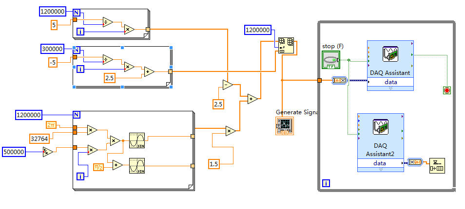
The fitting requires a fishing signal (32,764 KHz) saw tooth (0.3 Hz) signal output to drive the laser and acquires the signal from the output of the detector. I use the NI USB-6356 data acquisition with the speed limit of 1.25 MECH. / s.
I put the generation mode like "Samples continues", samples of writing/reading of 1.2 M and 500K (Hz) frequency in the DAQ Assistant. I also tried 500K and 500K.
The scheme of vi is illustrated in the following figure.
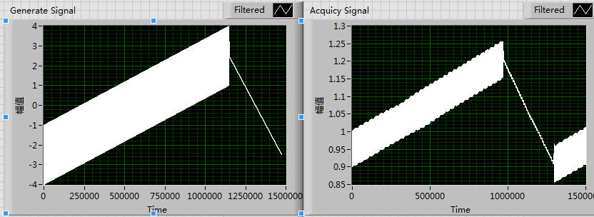
Of the front plate, the generation of signal is normal, which may be seen in the left side of the following figure. But signals a lot of periodic fluctuations that will appear if the right side of the figure. In addition, the siganl acquist go all the time.
I think it's maybe a few errors with my setting of the sampling frequency, I tried a lot of time for a change of pace, but it seems unnecessary.
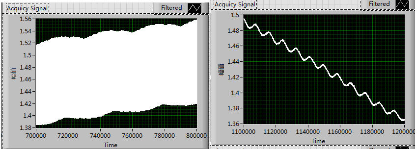
These fluctuations exist not only in the growing period but alos can be seen in the declining period, which is shown in the following figure:
I tried to solve this problem for almost a week and try a lot of different rate, but all fail.
Could someone give me any suggestions please? Thank you very much!!
Thanks SOSOSO much for your reply immediately every time!
This is my first time to write the Labview program with data acquisition
The attachment is the field of Vi.
I'll read the Web page that you offer, thank you very much once again!
Maybe you are looking for
-
The module will not activate with restart of Firefox. Vertical toolbar 1.0.9.1
I first tried vertical toolbar that is displayed in the search list. It helped, but the developer said this was not necessary more and me directed by a link. He had an add-on Mozilla on which I clicked. He says that you need to restart after a restar
-
Secondary asynchronous dynamic distribution
Hello A little, I have a problem with the help of screws of class member in a secondary school. Take a look at this project, I joined to the VI for an example of what I'm trying to do (in LV 2011). Basically, I want to decide based on a user selecti
-
What is agent of Acresso software manager and how do I get rid of him?
Acresso software agent manager attempts to access the internet, what is this program?
-
Video clips/photos download on 'My Documents'
I could not download pictures from a memory card, the camera directly, either by a card reader. I don't know if the problem is with the computer itself or Windows XP
-
No popup of parental controls (can't do anything this parental control need permission)
I had on my computer one day and there was no photo in the round back of the start screen so I tried to reinstall windows vista, but the screen has become weak as need my permission, but then he returned to normal and has nothing I restarted and tyie