High speed continuous measurement of encoder with sampling frequency of 1 kHz
I am able at all times the position of a linear encoder using a PCI-6602 counter card, and I need to know how to set up so that the counter rotating at high speed, but the data is inserted into the buffer at a frequency of 1 kHz. I am able suddenly to a hydraulic cylinder, and I am not concerned about the event recording to high frequency except to the extent where they throw off the number considerably if the equipment does not run fast enough to detect all the impulses of the encoder.
Now, I think is that the external sample clock signal control (routed internal pulse output counter) time rate whereby the equipment detects the impulses of the encoder and the rate at which it inserts data into the buffer. With a pulse 100 per inch encoder and a sampling frequency of 1 kHz, the extended final position of the cylinder is turned off by +/-0.15 inches, which is unacceptable.
I need calculate a speed of this information, so I prefer not to use software timed sampling to control this (it's more difficult programming for other reasons as well - several asynchronous measures). Any ideas on how to configure the hardware to count faster than the speed at which she inserts counties in the buffer?
OK, you're clearly on the right track here, so I will focus on some details.
1. How do you know that the +/-0.15 "differences are * measurement error rather than * error of movement? Why wouldn't be an accurate measure and a proposal which can vary slightly from the nominal value?
2. I wonder some all electric noise and defects that may produce false edges. The fact that the behavior was better by using a sampling rate limited (200 kHz) in the digital inputs may be that some of these flaws were so short that they were never captured.
I did a ton of work with the Commission to 6602 encoder and I can certainly confirm that count equipment is sensitive to the edges in a few tens of MHz. (I know its 80 MHz for edge counting, but I think I remember that it can be of the order of 20 to 40 MHz to accommodate the time of signal propagation extra of the quadrature decoding circuit).
A small point of clarification. You're talking about the speed at which the meter "works to. The value of count is a register whose value is changed completely by the circuit, * independent * of the sampling frequency. If you enjoy with material-clocked County in memory buffer or interrogation of software without buffer not a bit for circuits that increments / decrements the value of the counter register. (In other words, I am completely convinced that you would get commensurate with position end even if you took only 1 sample software-polled after the end of the move instead of sampling at 1 kHz all the way through.)
So, if the value of the counter is disabled, it is because the circuit detects producers of County of the edges that shouldn't be there. Something you can try is to set up digital debounce filter for input lines of the PFI corresponding to the encoder Source inputs and to the.
-Kevin P.
Tags: NI Hardware
Similar Questions
-
Change the value to trigger record data for 1 s sampling frequency of 50 KHz
Hello
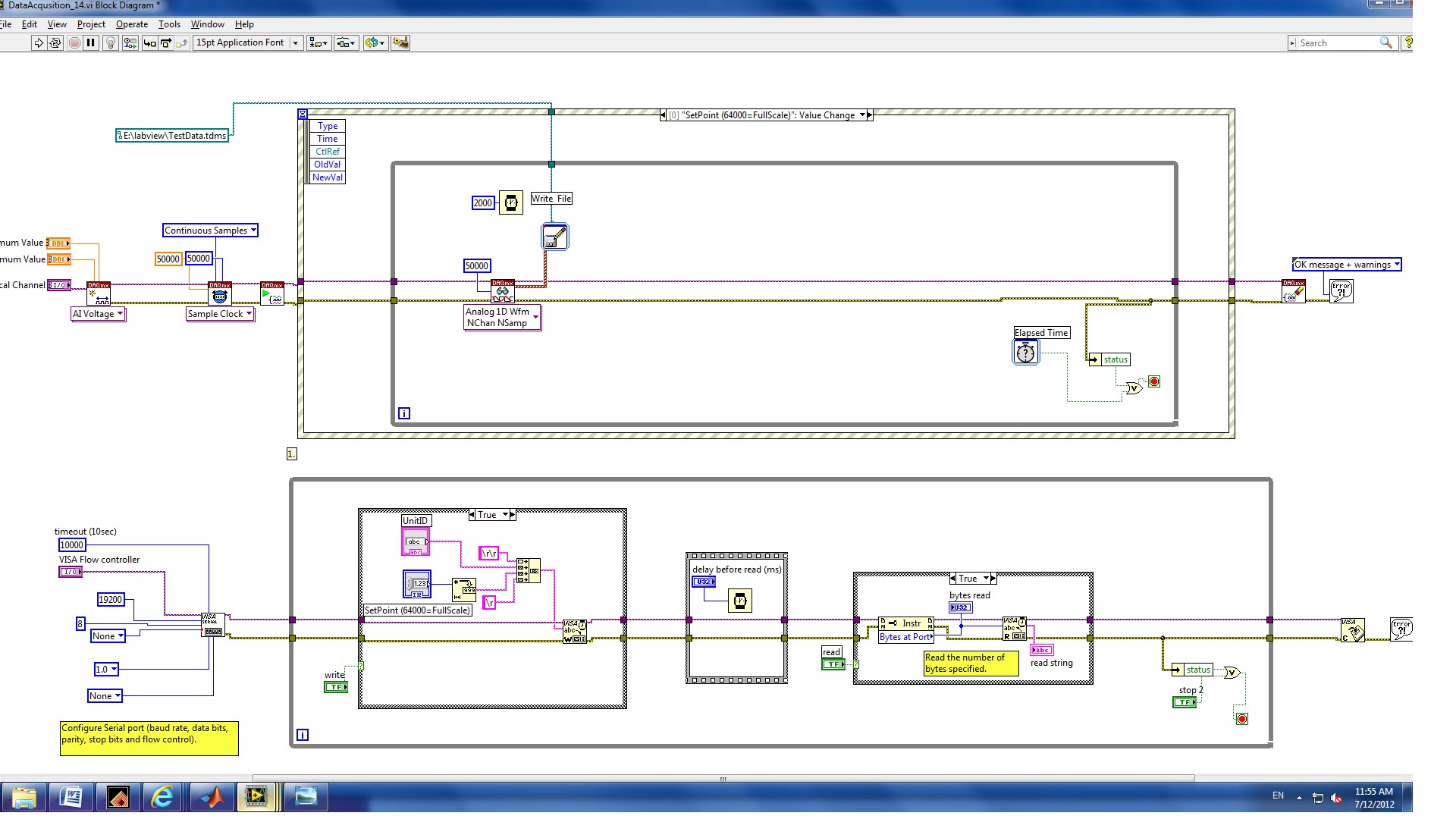
I have a VI with NI9215 and cDAQ-9178 chassis hardware. The function of the VI came out an instruction to RS232 interface and record 1 second of data every time that the set point is changed.
The procedure is
(1) modify the policy to the flow regulator
(2) wait 2 seconds.
(3) record of 4 channels for one second to the sampling frequency of 50 KHz.
At present, the problem is for the first edition of this program, two seconds (rather than) data was saved and corn, the error message 200279.
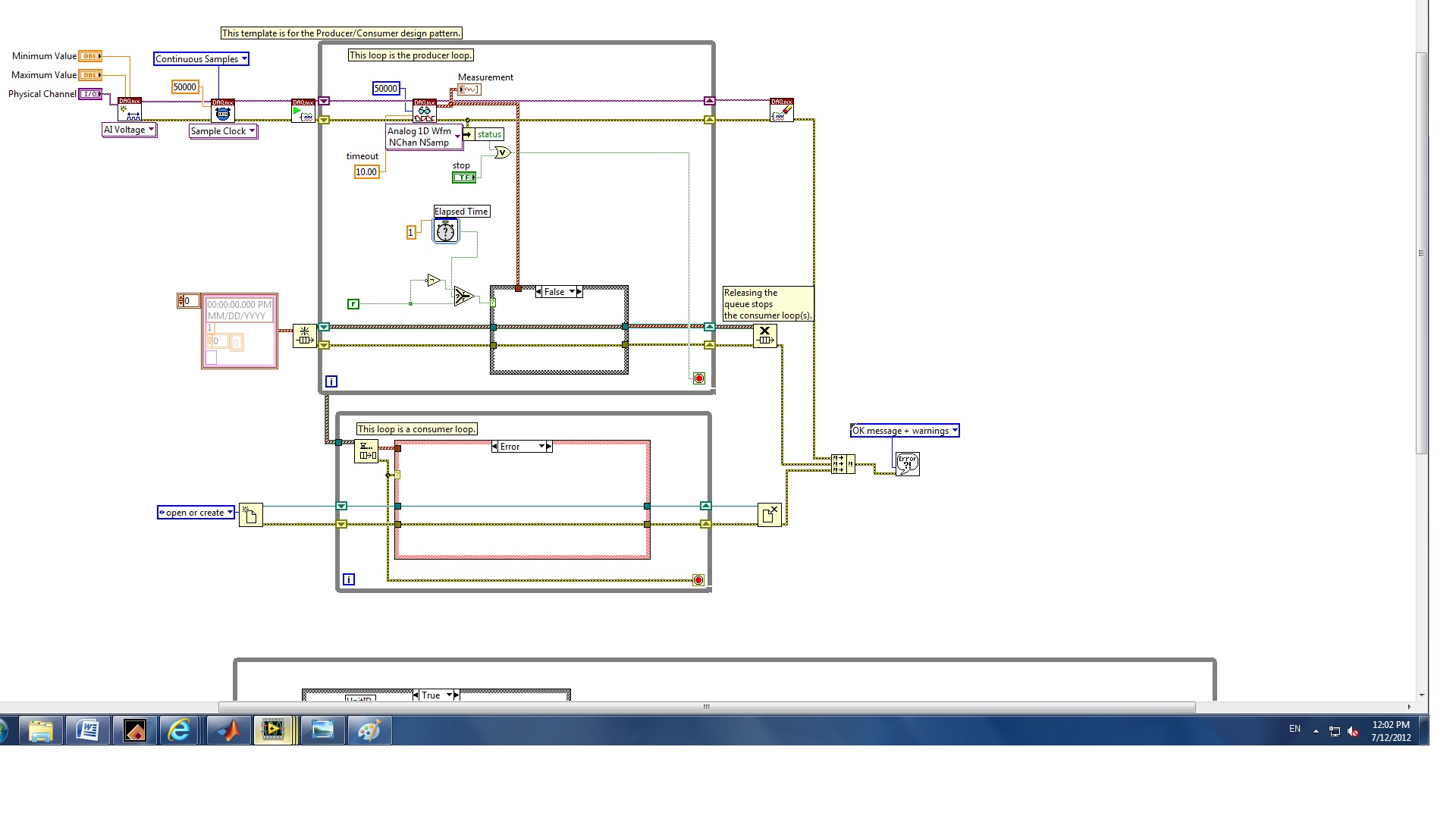
II. I revised for the second edition of the structure of the producer and the consumer who can increase the speed of the buffer.
The question is how to configure the trigger to start the backup of data and limit data save for one second whenever the set point value changes.
(1) which edition is best for my application?
(2) how to trigger the data record?
(3) how to record only a second of data?
I also checked this announcement and the elapsed time seems not to work for this case.
Any help would be greatly appreciated!
Melody
Hello
you have not used properly the nodes property.
1. replace the case structure in the first loop, with DAQmx features, with a structure of the event. Change the event fires for a worth of control of the setpoint change.
Edit: as stated in your first post, use the structure of the event, but put inside the while loop.
2. DO NOT connect error output from the stop command property node. Replace it with a local variable for the stop button.
Try these and let me know.
-
DAQmx task Read DAQmx with sampling frequency of 10 Hz produced much too much data
I have a simple configuration with a strain of channel 4 OR-9237 amp holds a carrier of series C of WLS - 9163 (wired ethernet mode) - Details probably does not matter.
I used MAX to create a DAQmx task associated with which all four gauges samples. The calendar setting is "Scan Loads" is continuous sampling, 2 k buffer (read samples) and 10 Hz rate. I guess that this task would generate 40 data values per second - 10 for each channel.
I have a simple loop of reading using DAQmx Read.vi that works always (without any stimulation time). Playback is set to read all available data and then pump it into a table.
In the attached example, I also added a few words of debugging to stop the loop after N iterations.As the loop is programmed with a 0.2 second period, I expect each pass of the loop to read about 8 samples or 2 samples per sensor. Instead, I get hundreds each passage. It's like reading has substituted the sampling frequency specified in the task of the unit. I absolutely need data to be material to the rhythm.
Where have I lost?
Thanks Adnan,
I changed your example I selected 'Strain gage' entry analog and then lowered the minimum and maximum thresholds to +-1-2. What happens is that each other in the loop, I 2048 samples or zero samples. The display flashes a whole line and then it clears any other past.
In response to your second post, I understand that the loop cannot run quite right that I select. I think that, but at a sampling frequency of 10 Hz, I have to sleep on the software side for nearly a minute before I built 2 K samples.
I played with the frequency of sampling, assigning to various values from 0.1 to 10000Hz. The behavior is the same until I approach the high rates where available samples remains to 2048-4096 sometimes, the display becomes continuous.
Ahhh, Darn. Yet another search was this link that points to the root of my confusion. The 9237 can taste arbitrary rates using its internal clock. Duoh! I wish that the pilots are smart enough to warn you if there is a discrepancy between the selected sampling rate and capabilities of the device
-
To begin with, I am very new to labview and unfortunately on that my first task is to build something rather complicated for a project that my company works. Fortunately it is especially followed rather than control critical processes.
Currently, I have a cDAQ with modules, DI, AO, and TC.
cDAQ-9133
NEITHER 9472
NEITHER 9421
NEITHER 9263
NEITHER 9205
NEITHER 9212
I'm currently running read-write for all 5 of these modules in parallel while loops and analog and digital inputs/outputs modules that all work as expected. Each loop requires 1 sample per channel through the wizard DAQmx etc for each module and I got can interact with all the asyncronosly inputs and outputs which at the moment is the goal. I can switch power switch for each module save memory, or if the need arrives later.
My problem is that the module TC (NI 9212) when tilt on which allows the acquisition of sample 1 loop seems to take much, much longer to collect samples. I have played with different acquisition parameters and can seem to get a continuous flow of data when you use streaming samples, or even when specifying N-samples but I come in questions where the "application cannot catch up with the hardware.
I tried to find an optimal number of samples/sampling, rate, etc I can get an update of temperature more than every 1 to 2 seconds, but if I set the number of samples that are high enough to apparently get a constant flow, what ends up happening waveform graphs seem to lag behind the actual data, and that's where I get errors. I only want 1 sample per channel per cycle anyway. Yet once, all the other modules in the cycle with less than 100ms delay between acquisitions but the module thermocouple ends up being 1-2 seconds. It's okay because in our application temperature should not rise/drop very quickly but its boring nonetheless.
I have the acquisition set up for the same (NI 9212) thermocouple module was like my modules of analog and digital inputs (NI 9205 and NI 9421) take 1 sample every time the task is called so I'm having a hard time understand why do the same for the TC module introduced such a delay. Max sampling rate is supposed to be 95 samples/s/ch, so I guess that the delay must come from call the task over and over again in a loop.
Synchronization and how you have configured the 9212?
In the case of high resolution, it can reach 1.8 samples/s. see page 7 of the plug technique here for rates for the supported modes:
http://www.NI.com/PDF/manuals/374389a.PDF
-AK2DM
-
Xincrement is not agree with sampling frequency
I use two PXI-5114 scanners that are being synchronized. I am taking 5 seconds worth of data. I have = 1e3 sample rate and record length = 5e3. I get only about 1.3 seconds worth of data. I looked at the actual length of the record and the actual sampling frequency outputs and they said the same thing as the façade made. I looked at and then the info out of the Cluster.vi of Fetch NiScope Multi Wfm and he had the same record length, but the value of Xincrement is 262e-6. This fits with what I get. Any ideas?
Thanks in advance.
Hi AT1,.
Thanks for posting. What you see, this due to the fact that the minimum sampling rate of the PXI-5114 is 3.81 kech. / s. The digitizer will force any value less than 3.81 kech. / s up to this value, so a record of 5000 samples take 1.31 seconds to acquire. If you are looking to acquire 5 seconds worth of data, I recommend to increase the length of record about 19 050 samples, which should be about 5 seconds worth of data. Let me know if this would work for your application.
Kind regards
Joe S.
-
Impulses per kilometre high-speed conversion/measure
We are currently working on a system of data acquisition for an electric boat. We have a GPS speed sender who transmits the speed of the boat regarding the impulses per kilometre. We can get LabView to detect the input pulses, but have no idea where to go from here, with regard to the transformation of this measure in miles per hour or meters per second. Any help would be greatly appreciated. Thank you.
Hi E-boat,
It seems that the task is time just do not get a sample. On your VI reading, you should be able to set the time-out value a much greater value. Otherwise, you could code around the error by deselecting the error and restart the task when that happens. Let me know if you have other questions about this. I'm glad to hear that you are facing up and running!
-
Capture high speed encoder data
Hello
I have a motion control project where I would record the position data. High speed capture is limited with sampling frequency of 2 kHz. But I have to save a lot more than higher speed.
I read that there is another option that connects to the motion control card (I use a card PCI-7358) and the map of data acquisition using a RTSI cable and channels A and B of the routing of the data acquisition card encoder using the RTSI lines.
I have 6143 and 6280, 7358 PCI DAQ cards and a RTSI cable.
Q1. Which card is better to use? 6143 or 6280?
Q2. When I look at the examples, I have seen that its possible to phase has the traffic and signals of the phase B of an encoder for the RTSI line with Signal Select.vi. But I couldn't find an example on how to read of DAQ card.
Q3. How can I contact the encoder position phase has and band B pulses which is acquired from the DAQ cards?
Concerning
Hi serkanb,
The 6143 has no support for measures of encoder quadrature (although you can run a task of count of edge and use the B signal as a line up/down to get a similar effect). If you are interested, we'll find more information here (the 6143 uses the same SC I ASIC that make the E Series DAQ devices).
It doesn't really matter too much since you have a 6280 that supports quadrature encoder measures (he uses the STC II ASIC). To answer your direct questions:
Q1. The 6280 is better (see above)
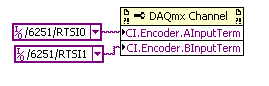
Q2. You need to use a channel DAQmx property node to choose what terminals to use for your task of encoder:
Q3. I would like to start with an example of the expedition:
Help > find examples... > input and output material > DAQmx > counter measures > Position > measurement Position.vi
You insert the property node before starting the task (but after the channel is created).
I hope this helps, if you have any questions do not hesitate to post back!
Best regards
-
Treatment of LabVIEW data and high speed data acquisition C
Hi all
I am designing a data acquition VI high speed of 3 cards acquition of data at the maximum speed. Data cards are PCI 2517 Measurement Computing. The sampling frequency for each card is 1 M samples/second, if the total sample of M 3/second of three cards. Problem is the LabVIEW drivers and the screws provided by the provider works very well just for a single card at maximum speed, but does not support multiple cards at maximum speed. Their technical engineer advised me to write code in c#, C++ or VB.NET for this data acquition high speed. If I use C forever, I would like to use LabVIEW for processing of the acquired data to data acquisition. I came across a few examples that suggest the creation of dll C code and then calling it a LabVIEW. But those who have programs simple and none of them speak in C data acquisition. My questions are,
1. is it possible to call a C data acquisition program high speed of labview and not work in any kind of present of buffer overflow?
2 would it not simple best to use labwindows CVI?
3. is there another alternative solution that I'm missing?
I'll appreciate all the entries.
Thank you!
Nilesh-
It's pretty easy. Arguments for CINrun must match wiring. You can wire your CIN function block and say LabView to generate the C interface code to begin.
Here's my pairs for the ASIO audio project.
All the best,
Terry
-
Synchronization of the inputs and outputs with different sampling frequencies
I'm relatively new to LabView. I have a NOR-myDAQ, and I am trying to accomplish the following:
Square wave output 10 kHz, duty cycle 50%.
Input sampling frequency of 200 kHz, synchronized with the output that I get 20 analog input samples by square wave, and I know what samples align with the high and low output of my square wave.
So far, I used a counter to create the square wave of 10 kHz, display on a digital output line. I tried to pull the document according to (http://www.ni.com/white-paper/4322/en), but I'm not sure how sample at a different rate than my clock pulse. It seems that this example is intended rather to taste one entry by analog clock pulse. There may be a way to create a faster clock (200 kHz) in the software and use that to synchronize the analog input collection as well as a slower 10 kHz output generation square wave?
I eventually have to use the analog inputs to obtain data and an analog output to write the data channel, so I need the impetus of the square wave at the exit on a digital PIN.
How could anyone do this in LabView?
Hi Eric,.
All subsystems (, AO, CTR) derive from the STC3 clocks so they don't drift, but in order to align your sample clock HAVE with pulse train that you generate on the counter, you'll want to trigger a task out of the other. I would like to start by a few examples taken from the example Finder > Input and Output material > DAQmx. You can trigger GOT off the train of impulses, start by Gen digital Pulse Train-keep -you probably already use a VI like this to generate 10 k pulse train. AI, start with an example like Acq Cont & chart voltage-Ext Clk - Dig Start.vi-you'll want to use the internal clock so just remove the control of the "Source of the clock" and it uses the internal clock. From there, simply set the "Source of the command" either be the PFI line generates the meter, or ' /
/Ctr0InternalOutput '-assuming that you are using the counter 0. You'll want to make sure that the start of the task HAVE faced the task of counter I is ready to trigger off the first impulse. They should be aligned at this point. For debugging, you can use DAQmx export Signal to export the sample clock - you can then brought the train line and the PFI pulse to make sure that they are aligned.
Hope this helps,
Andrew S
-
A measure of speed high speed with encoder in quadrature and NI 9401 on cDaq
Greetings,
We use an encoder in quadrature with 360 pulses/turn on the tracks (track A and B) and no trace of Z to measure motor speed at startup. Data acquisition, we use a NI 9401 in 9178 cDaq chassis and a pc with LabVIEW. The problem is that the start-up period is relatively short (less than 1 second), during which we measure speed as precisely as possible. The speed range is from 0 to 10000 RPM.
What type of measurement method that you would recommend.
Here are a few methods that we have already tried:
-Measure with DAQmx CIFreq--> high frequency with 2 counters: speed measurement, but with a very big mistake (+ 166 RPM).
-CIFreq DAQmx--> wide range with 2 counters: good speed data but more slow measurement,
-CICntEdges DAQmx (counting separated the two lanes, speed conversion): very incoherent speed data.
Thanks in advance for your help.
Matej
I would definitely say a 4, the measure of a low freq called option with 1 meter. (Frankly, I've never been
fond of this name because it is useful for freqs much higher than what I expect most people think "low freq".) This
is the method that I almost * always * use for frequency of counter measures. It works really well to capture transitional
variations in speed.
10000 rpm and 360 cycles/rev, you are looking at a maximum frequency of 60 kHz. The frequency measurement mode 1 meter
There will be 80 MHz internal clock by encoder cycle edges, then you will get more than 1000 strokes per measure. The point
that means only 1 number of quantization errors, you can expect<>
Further, you can average overall, say, 10 samples to you give even better accuracy and you could still be a data capture
rate significantly higher than the probable bandwidth of your mechanical system. (The average would just clean the jitter and noise and would not
Hide answer true mechanical characteristics).
-Kevin P
-
Data acquisition high speed (200 ksps / s) with pci-6224 or usb-6211 is possible?
Hello
I need assistance to complete a task.
The task:
Record a switch contacts twists every 5 microseconds (200 ksps / s). DAQ cards I have at my disposal at the present time are PCI-6224 and the USB-6211. The two cards are rated up to 250 kech. / s. I only watch 1 channel that will monitor the voltage.
Here are the settings I use:
CSR
Continuous samples
Sampling rate of 200 kech. / s
Analog DBL1 1 sam chan
timeout of 10 seconds (Read DAQmx)
The problem:
(1) every time I try to taste 200 kech. / s I get an error that reads
Measurements: Tried to read samples that are no longer available. The requested sample was already available, but has since been replaced.
Increase in the size of buffer, most frequently the reading of data or by specifying a fixed number of samples to read instead of reading all available samples would correct the problem.
(2) when you try to taste at a much slower pace of 50 kech. / s, the speed of the loop iteration is not realizing this speed setting.
My question is this: are these 2 cards (PCI-6224 or USB-6211) DAQ fast enough at my request and I do something wrong? OR
I use the wrong hardware to accomplish my task?
Thank you in advance,
Gerardo
The number of iterations has nothing to do with the number of samples if you do it right. You specify the rate and the number of samples you want and number of samples returned. You DO NOT loop 200,000 times. If you ask for 200 000 s/s and 200,000 samples, you will get this number of samples every second. It's really as simple as that.
-
acquisition of data high-speed and simultaneous sampling
I'm quite familiar with the coding for NOR-DAQ boards in Labview. What worries me with labview, is that each tick is about milliseconds. I intend to retrieve the data simultaneously from 32 channels at 2 MS/s/chan using SMU 6368 s. Wouldn't not possible to enter data, on average 20 to 50 samples to get a unique value, perform simple algebraic manipulations on it and send it to the PC / software to approximately tens of kHz? We already have labview code to perform similar tasks, but it is quite slow and limiting the rate of experience. I said that Simulink is slightly better than Labview in this regard, but suffers a poor user interface and that if something C/C++ offers the ability to perform at high speeds with the same cards OR data acquisition. Could someone advise me please on this issue?
You can use your PC! You can use a PCI/PCI-e card as the interface to your computer and it should work perfectly. Take a look at these pages (http://sine.ni.com/nips/cds/view/p/lang/en/nid/10389) for more information.
-
T3i sync high speed with popup flash?
When shooting outdoors with a light background, it would be nice to be able to use the flash pop-up as a fill light (to the shadows on a face, etc..). However, the shutter speed is set to 1/200 when the popup flash is in place, overexpose the scene. Is there a reason why the pop-up flash can't sync high speed like an external flash to allow a faster shutter speed and always get a filling?
Thank you
David
It has to do with the amount of energy is available for the flash. A more powerful flash can more easily manage the sync high speed.
Sync and sync high speed are related to the work the Shutter curtain on any SLR digital. There are two doors. A slides open, and close other slides. The reason for which there must be two doors (instead of one) is because that if there is only one, then the door would slide open, then reverses to slide.
Assume the following scenario were true:
Suppose it takes the shutter a full 1 second door to slide open. If we set an exposure time of 2 seconds, the following should happen if there was only one door.
-l' shutter starts to slide open from left to right, allowing light to reach the pixels on the left edge of the sensor. The right edge is always in the dark.
-as slides of doors, more and more pixels are eposed to light.
-a second later reached the opposite end and all the pixels are exposed to light, but the door must immediately reverse and start close because it will take a full second to slide the door closed.
-the door begins to move and immediately the pixels on the edge of most on the right are in the dark, because they are covered by the shutter, but the pixels on the left edge are still exposed to the light.
-the door has finally reached the edge against a second later and no pixel is exposed to light.
Think to what just happened... the pixels on the edge of 'left' of the sensor got a second exhibition 2... but the pixels on the right edge of the probe were barely exposed for a fraction of a second. You'd have a horrible blow to look.
To resolve this problem, the camera uses TWO doors... begins a sliding open... the other follows a moment later (based on the selected shutter speed) and starts sliding closed. Now, all pixels are exposed for the same period of time, regardless of the shutter speed you use.
But the reality is they are mechanically sliding doors and it takes time to move. Flash sync speed is shortest possible exposure that can be turned where the first door has enough time to COMPLETELY slide open so that when the flash goes off, the entire sensor is exposed and benefit of lightning. The second door can slide THEN closed.
If you do not use flash and you set a very fast shutter speed (say 1/1000th) the second door actually starts closeing long before the end of the first door opening. In fact the second door is "hunting" the first establishes a "slot" which sweeps the sensor.
With this in mind... now think just what a flash how to predict sync high speed.
Assume that your camera has a maximum speed of flash-sync of 1/200th, but you want to shoot at 1/400th.
This means that the first door must begin to open. When he reached the midpoint, the flash must trigger to light the subject - but half the sensor did not lightning. The second door closes as the first door continues to open up. When the first door reaches the opposite edge, the second door will now be in the middle. The flash needs to fire AGAIN - this time to expose the pixels on the 2nd half of the sensor.
This means that the flash should fire TWICE in quick succession and the impulses must be PRECISELY 1/800th second (half or your second 1/400th total exposure times) apartment. No flash would be able to recycle in just 1/800th dry if she gave a burst of the power of the light. In other words, that it must reserve at least half of its power for the second round.
If you increase the shutter speed to 1/800th... now the flash to trigger FOUR times and no single burst may be stronger than 25% of the power of lightning - and gusts must precisely timed occurs 1/1600e seconds, independently of the other.
You can quickly see how this is going to require a flash with a power or you won't be able to finish the sync high speed on something more than just a few feet.
For the light of day, the most brilliant exhibition is going to be the sunny 16 rule... f/16 with the shutter speed, the value in contrast to ISO. So, for 100 ISO, you can use 1/100th sec. To f/8, you can use 1/200th (and now you are still below the max flash sync speed).
-
Fan runs continuously at a higher speed
I have a HP laptop. This problem started a little over a month ago: the fan started to run constantly at high speed and I was afraid that my LT was overheating so I went online to find solutions and the offered was "cleaning". I blow the air frequently, because I have a dog. So without taking it apart, I think it's relatively clean.
After 'cleaning' didn't solve the problem, I have blocked some programs (many) start with the startup of the computer. That worked wonders. Not only the fan seems to 'calm down', but picked up speed and freezing (flash plugin AHHHHH drive) until reduced to a minimum.
Now, he resumed running continuously and at high speed. I went to check and make sure that the start menu had not changed. It seems still good. When I run the Task Manager, it will display an application that is running, but 20 to 30 processes and services from 50 to 60. I have maturities adjust this number if I knew which ones it was safe to stop. I tried Googling some of them, but could not understand what is needed and what is sure to stop and exactly how to do it.
Any thoughts?
M
Rather than guess about potential overheating, download a program to monitor material as one of the following conditions:
As much as that processes and services 'need' to be executed, you essentially already do the correct thing - searches on the names online. If there are specific processes or services that you wish to get more information, provide the names and maybe someone here will have some tips (without guarantee).
You can also right click on one during the process in the Manager of tasks and select Properties. The location of the file (under the general tab) and information on the Details tab can provide clues about what made the process.
-
Portege Z30 16 GB with high speed Port Replicator III and two monitors - resolution
I have a Portege Z30 with 16 GB of Ram, connected to a Toshiba high speed Port Replicator III which is connected to two monitors running in mode extended.
The monitor attached to the first section of the video is 1920 x 1200 running.
However the second monitor is only show support for a maximum of 1280 x 1084.The monitors are identical, and both are connected by DisplayPort cables.
I tried to lower the resolution and save the settings on the first monitor to see if it offered options on the second monitor, but the options remained the same.
At this point, I have narrowed down to 1280 x 1024 so that it conforms to all the monitors but would like to a plus-res solution.
Does anyone know if there is a fix/work-around for this?
If this is a hardware limitation, has anyone tried a USB 3 to DisplayPort adapter in a similar configuration?Thank you!
At the same time using two displayports?
I wonder how it is possible, because of my knowledge it is not possible... as far as I know the Port Replicator III supports two DisplayPorts but you could choose and use one of them...In any case, you can use both with a lower resolution, I guess that this problem can be caused due to incompatible display drivers.
I suggest you to uninstall reinstall or update the display drivers and check if it helps
Maybe you are looking for
-
I use an iPhone 6, 64G. Running iOS 9.3.1 (I3E238); It comes with the music on the iPhone app. My phone was stolen and I restored the replacement using iCloud. Everything works, and all the information has been restored except music. I tried enab
-
the iPhoto on external hard drive library hangs in the print mode
I use iPhoto 9.6.1 on OS X Yosemite (10.10.2). I have a photo library on an external drive. I tried to print a photo several times, but it failed to print. Since yesterday I'm hanging in print for this particular library only mode. I don't have this
-
I want to keep up my vista, but first I want to clean my hard drive, I don't have to return to the top of the original, it is possilble
-
using georeferencing for gps software, since 2 months I invariably "memory insufficient No. 4" when I load a map of en 50 a100 jpeg MB, whereas previously all fonctionnaitparfaitement. This under another computer with XP don't detail attached and dul
-
Original title: isass.exe - application error application faild to initialize properly (oxcoooo142) click on ok to end now screen black with white arrow will not even stop what should I do Reference Dell Dimension 4700c Ihave try F8 F1, f2, F12, and