How do I output a digital signal to an analog signal
Hi all, I use a PCI 6221 with LabVIEW 2010 (no add-on) with the CB-68LPR connection block and I want to use an input signal analog of voltage of between 0 V and 5 V of an LDR to change the brightness of an LED, so I can maintain a stable lighting for a webcam capture feature level image and treatment system.
I can get the analog input voltage of the LDR (set up as a voltage divider circuit) using the DAQ assistant, via the channel of Ain 0 on the use of pins 68 (AI.0), 67 (AI GND) and 14 (+ 5 V) and write it in a graphic and digital display but I don't know how to write the value to a PIN that can be used for PWM I think assistance from pine 40 PFI 13 P2.5 and a digital (GND pin 13).
I looked at the example of code that was written to produce a PWM signal, but these programs don't signal to a device/circuit, they are just "nothing stuff" that the PWM signal to a graph.
Can someone help me or direct me to tutorials/code examples which are of real-world applications?
Hello
PWM can be done in DAQmx using a task of the meter output.
I think that example 'PWM-Counter Output.vi' goes quite a long way to do want you want I think. It is located in the LabVIEW examples of shipping.
I also found here:
http://zone.NI.com/DevZone/CDA/EPD/p/ID/1710
This could be useful a read thus:
http://zone.NI.com/DevZone/CDA/tut/p/ID/2991
Let me know if it's of any help.
Tags: NI Software
Similar Questions
-
How to out high-level digital signal (5V from 1V) on usb-6210?
Hi, I work with a OR usb-6210 and so I did not all channels of analog output that I can use. I hope that I can use the digital output for my application because I am creating a switch I can synchronize my editing. I need 5V output for my device run and currently, I am only able to get 1V.
-Teo
Outputs digital are dip lent TTL of the stent, since, your load is attractive more current that can provide the device and drop the voltage. Please provide information on what you are connected to or look at the other posts where users have had exactly the same problem. You probably just a conductor connected to the digital output.
-
2 digital signals keep using pxi 6544
Hello
I wonder how I can generate 2 digital signals that continues and I will able to make even phase, or different phase 1/2, or 1/4 different phases. And I need them to be able to their output in any channel (free) my PXI 6544.
I've seen examples of generation (no script), but most of the examples shows just how to generate data in parallel. Generating script I use to achieve this? Repeat for the thing?
Kind regards
Yan
-
How can I get digital signals (interface UART) with a microcontroller with NI USB-6008?
I have acauired a few analog signals by A/D (3 channels). I put each scanned data on 3 digital output with a microcontroller. I want to see if it is possible to import these digital outputs 3 to a PC via a USB-6008? It's like the connection of the output to the digital input of the USB-6008 and import the 3 channels simultaneously to LabView? Do I need to use some other hardware like USB-8451 and connect the clock of the MCU to USB-8451?
Saraydin,
The digital I/o on the USB-6008 is a software program only, so unless your signals are rather slow, it probably will not work for you. In general, the procedure would be to connect each signal to one of the digital lines on the map and then set up a digital entry into LabVIEW task to read the three channels. If you use a device that has clocked by the digital i/o hardware, you then your input clock signal and use it as the sample for the task clock. Here is a list of USB devices supporting DIO clocked by the hardware. Also, there is an example that comes with LabVIEW, which shows how to do this. You can get to it in LabVIEW by going to help > find examples. When the example Finder window opens, navigate to hardware input and output > DAQmx > digital measures > Cont read dig Chan-Ext Clk.vi.
The 8451 is specifically for I2C and SPI, and would be great if you try to make one of these protocols, but otherwise I would recommend the devices in the list I linked above.
-Christina
-
How do I configure other digital ports except port 0 of daq 6351 acquisition of digital signals
Mr President.
I can acquire digital signals using 8 lines of port 0, but I have to get the waveform Digital 24-bit. So please tell me how to configure other DIO ports so that I acquired digital signals using these DIO line also
You should be able to create a task DAQmx to read Port0, Port1 Port2. When you read the DAQmx data, you must combine the port if necessary data table.
-
I have a DAQ Assistant configured to read 2 channels at the same time. When I have a graphical indicator of wire to the output, I see 2 signals mixed together. How I divided them into separate signals?
When I wire any type of indicator, it is show that a release of a single channel.
I want 2 indicators showing 2 different signals as expected from 2 channels configured. How to do this?
I tried to use split signal but it end by showing that 1 out of 1 signal two indicators.
Thanks in advance.
Yes you are right. I tried, but I don't have the result.
I just find the path. When we launch the split signal, we should expand it (split signal icon) by top, not the bottom. It took me a while to understand this.
Thank you
-
How to convert an analog signal into digital signal
Hello
How to convert an analog signal into digital signal, such that each sample of the analogue signal corresponding to 1.2V will be represented as '1' digital signal and other samples of the analog signal (which are not 1.2V) will be represented (converted) ' 0' in the digital signal.
And how to view the wavefroms or graphical indicators signals.
Thank you.
If you have 1000 samples and you want to convert to digital, you get 1000 digital values. Attached, that's what I mean.
-
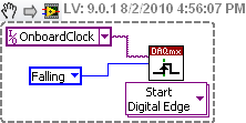
How to generate a digital signal on a negative slope of the clock?
Hello
I need to get out a finished length of the Digital pulse which will begin on request to the negative of the clock slope import (or export).
I try to get the clock, exported or imported, but in any case, I can trigger output signal on the negative slope.
What is the trick?
Thank you
Pawel
What camera you use to build your digital signal. What is the source of the clock? You can attach your vi? Normally, there is a function of data acquisition for configure the trigger where you choose the source of the trigger and the trigger slope (rising or falling), should be declining to a negative slope.
-
How to draw a part of a digital signal
Hello, I have a digital signal, and I would like to draw just the 10 first or second 10% of the curve on a digital chart. Could you please help me on this. What is memory, and the effective, faster way to do this.
Thank you
Use GET subset of waveform:
http://zone.NI.com/reference/en-XX/help/371361K-01/lvwave/get_waveform_subset/#Instance7
There is a polymorphic digital version of it.
-
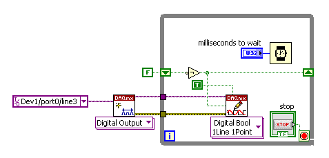
Problem with a digital output in the information of an analog input
Hello
I use a SCXI-1000DC module with a module of the SCXI-1600, SCXI-1531 module and SCXI-1163 module to receive an analog of an accelerometer signal and a digital signal.
I claim that the accelerometer is constantly monitored, and the output is on when I want to, by an impulse that I comand in labview.
I use a rate 25 k and a 12, 5K samples per channel on DAQmx Timing.I notice in DAQmx read, if I put a sample of hight by channel, the output is not there when I want to, and if I put a few samples per channel, I exit when I want to, but the program seems to be slow with the passage of time. I don't know how I can solve this problem!
I'm sorry for my English, and I hope you can help me.
Thank you
Silvia
Hello Silvia,.
If you ask a larger number of samples, the labview diagram will stay longer in the DAQmx Read function, so the while loop runs slowly, and the digital output is updated less often.
I suggest that you use 2 separate while loops: one for the analog input and the other for digital output, so that each loop might run at a different speed.
Best regards
-
How do I output up to 8 high and low?
Hello
I'm still new to Labview, and I can't seem to find a way to do something fairly simple.
I have a device that has 8 entries, and each entry is "lit" by providing a high signal (5V). I would like to use Labview to provide that these high and low signals to these 8 output pins. An additional intracacy is that each channel will have to be activated or deactivated by pressing a button of Labview. What commands/functions labview I should use to provide this feature? Are there related examples in Labview or online? Thank you very much.
I use a NI 9401 to provide these 8 output channels. http://sine.NI.com/NIPs/CDs/view/p/lang/en/NID/208809
John
You can search for examples on how to produce digital signals. Go to help - find examples and numeric type and get labeled examples "write dig Chan". There is an example that will run on the 9401. Then, you can adapt it for your use.
-
MyDAQ - generation of a digital signal and display on an analog waveform graph
Hello
I use the MyDAQ OR generate a digital waveform with a Frequency adjustable. This is implemented in a program, I already wrote it, which generates a TTL 'like' impulse out of the sound card. I display the result on a graph of analog wave form, and I would like to be able to display the digital signals generated by the myDAQ on the same graph. (Not in the same time, one or the other, activated by a button). I've been messing around with tables and conversions, but I can't really do with all this.
It's the vi, I did to generate the digital signal of frequency with MyDAQ. Any suggestions on how to do this if the following is false, would be great too, as I just got the MyDAQ a few days ago. I think there must be a better way, but it's the best I could come up with so far.
Hi Jonny,
The General logic, that you use to create a digital pulse train is very good. This VI you wrote should work and create the pulse train based on timing of software (which is fine because you have not DIO clocked by the material on the myDAQ anyway). However, it is generally advised to start the DAQmx task just before your time loop and then disable the task after the while loop when you press stop.
For reference, there are a few examples of good enough LV that I recommend you watch too much for this application. If you try just to create a digital pulse train, the example Gen dig Pulse Train - Continuous.vi is a good example that uses a counter to create a digital pulse of your desired frequency train. It is generally the preferred method to create a pulse train, if you have equipment available to do (the myDAQ there a meter). Otherwise, there are a few examples DIO who write continuously in a digital line / port.
If you are unfamiliar, you can find the examples by clicking Help > examples find... into LV then navigate to hardware input and output > DAQmx > generating digital impulses or the digital generation.
Also, here is some additional information on the myDAQ and its counters:
Hope this helps.
Chris G
-
No digital signal to headphones Jack S/pdif - Satellite P100-227
I have the Satellite P100-227, I brought a lot of different types of cables and adapters for trying to get a digital signal to headphones s/pdif Jack (the manual says that the helmet and S/pdif share the same socket). I tried a cable optical toslink to an adapter optical 3.5 mm but I can't not all digital audio of this laptop. It seems strange that there are a lot of output video but not audio Digital 5.1?
Why can't they provide a daily normal production as an audio output optical digital toslink?
Hello Chris
I checked the specification for Satellite P100 - 227 (PSPA0E) and it is listed follow Note:
Audio Line out Jack S/PDIF - not availableGood bye
-
frequency of the digital signal 6009
Hello, how to generate the digital signal with frequency 50 Hz using NI USB-6009?
You can take a look at this:
Can I use a generation of impulses with the counters on the USB-6008/6009 case?
-
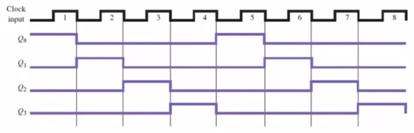
Graph of digital signal using binary numbers.
I need to generate digital signals 4.
I have created a binary number which represents the 4 signals. (I don't know if I integrate it properly).Issues related to the:
1. How can I represents the binary number (4 signals) in a digital chart?
2 - is the right way to generate digital signals?
I need something like this:
Your code is meaningless.
- Why you build an array with one element is there is always only one item?
- Why are you doing floating point operations dealing with whren of integers?
- Your VI does not have a digital signal graph.
Try something like the joint to rotate the pieces...
Maybe you are looking for
-
How to restore the flavacons that turned white in bookmarks after the last update?
with the latest update of firefox, all flavacons in bookmarks became empty. How to restore?
-
HP PAVILION P7-1155: p7-1155 graphics card with hdmi
I need to replace the graphics card for my machine to my hd tv hdmi output. I received a link to a forum that took me to newegg expert. There, I was overwhelmed for choice. I looked at a few of these, as well as comments. PNY cards seem to have a goo
-
It doesn't seem to be an official Yahoo messenger app for android, but there are several "all-in-one" apps on the market. Anyone here have preferences/suggestions for a good?
-
When the computer is, I come back and the screen is completely white. A few times it becomes white at the start.
-
Where is the plugin Eclipse and SDK 6?
Hey community,. I tried to install the Eclipse Plugin of BB with the SDK 6. So I followed THE instructions and at the end with the options in the image! So, how can I get the plugin and the SDK now? I what am doing wrong?