How generate the waveform analog multi simultaneously.
I use the relay Full.vi Gen to generate a waveform.
I want to create another form of wave and start at the same time.
Any suggestion?
Hi turbot.
The easiest way to make the two tasks simultaneously is to have two copies of this task in the block diagram. In LabVIEW, any function that has all its entries ready or a Subvi runs "simultaneously", so no additional real action must be taken to make them simultaneously. However, you must make sure that all entries of all your screws are to be executed simultaneously are ready at the same time (which means a set of functions that generate the wave does not need any input on the other). It's called the data flow model in LabVIEW. Read this for more information: http://zone.ni.com/devzone/cda/tut/p/id/6098#toc0
I would you suggest to use an other sub - VI for opening and reading your file (as well as use a different file for each reading Txt Subvi relay). You can also make your Subvi re-entrant. For more information on screw reentrant, refer to this link: http://digital.ni.com/public.nsf/allkb/98847B4E4C715E6D86256C59006B57CC
I would also say that you pass the path to the main file of your VI by using a control in your Subvi, rather than using the constant you have now.
Tags: NI Software
Similar Questions
-
How to read 3 analog inputs simultaneously with 6070E?
Hello
I wanted to read 3 analog signals simultaneously using cards of acquiring data NI PXI-6070E and Labview 2010.
I can with success read and record the 1 signal (which you can see in the attachment), but do not know and can not find examples on how to read 3 signals simultaneously. Any help, especially a simple example would be great.
Thank you!
Just click on = pull down from the constant physical channel, select Browse and shift-click or Ctl-click here to add other channels. You can also type in new channels with the ai0 syntax: 2 for three continuous channels for example.
-
How display the waveform acquired DAQ card separately in wavefrom graphic
I NI 9239 DAQ card and it has four channels. I need to create a user interface graphic labview in which I need to display all the forms of four wave separately. If I select all four channels of the daq assistant and connect the waveform table all four waves are coming to overlap... I need separately for the treatment... what should I do?
Thank you and best regards...
Try this
-
How convert the waveform on the table of waveform waving on waveform graph
Please answer now...
Your other post indicates it is a thesis, I consider homework. What did you do? What do you mean? What do you get a waveform graph? You have one, or the plots of 10? If you have a parcel, what you get as the data type for the data in the chart? If you have more than one conspiracy, what do you get? What is the data type that accepts a waveform graph? Have you looked to see how that is defined?
For example, let's say you have a parcel on your chart. When you get the data, you get... a table 1 d of values. It's kind of logic, right? Well, what is the type of waveform data? It consists of a starting point, time delta between points and an array of values. Hmmmm... So, what about using the wave function of build? Just a thought...
-
How does the option of multi site
I realize that Muse is not true "adapted" and you need to create a version for each platform, so how this work?
Lets say I created a desktop, Tablet, and the mobile version of my site. How to publish the project so that all three versions are active and how he treats people visiting the site on these platforms. Typo www.acme.com via mobile phone, for example, will take me to the correct version or is at - it a transmission, a code injection should be done to take the visitor to the correct site or are the three versions actually three completely separate versions?
Hi Christian,
Versions for desktop, phone and Tablet for a single site will be in the same file of muse. So, if the site will be accessible on any device, it will be automatically identified and appropriate version will be displayed.
Is attached a screenshot of the plan view to add the phone and tablet on the site.

Kind regards
Neha
-
Import MATLAB generated the file ascii in the Analog Waveform Editor
Hi all
I tried to create signals by the Analog Waveform Editor. I have some Waveform generated from MATLAB and recorded as ASCII files, following the instructions on this Web page OR, but it did not work properly. For example, if I produce a column to fill with 0.5 and import the file into the analog signal generator, all I get is a huge series of random number. I missed a few steps in the import of the waveform?
Thank you!!
Just for your reference, I could almost in half the size of your file just by saving as .hws. Also to answer your last point, you may have issues opening / importing your .txt file because it may have been opened in another program at the same time. Make sure that you have closed it in Notepad or Excel or other programs which may still be locking on the reference.
Kind regards
Jason L.
-
Generate the analog waveform based on the data file
I want to create an analog voltage output that follows I have a data file (excel, csv, text (which is easy)). The data file creates a waveform with equal time between steps (dT =.0034 sec). After the output through all the data points, I want it repeat indefinitely.
What is the best way to create the waveform of a data file?
To create a type of waveform data, calculate the dt by subtracting two values in column 1 and get the array of Y from column 2. If you save the file as a comma separated or tab text file, you can then use the spreadsheet file read. After obtaining a 2D array, you would use the index table and the subset of table functions.
Assuming you use a capture card data OR for the output signal, you can pass a type of waveform data to a writing DAQmx and set for the generation of types.
-
How to build square 3 ph pulses and use them to trigger the two analog inputs.
Task:
1) generate continuous 1 Hz ms 45 pulses on three lines of output offset 120 degrees.
Other neighborhoods, three phases (three outputs) 120 degrees out, but instead of sine wave should be a volt 5ms 45 along with a second ground pulse. I need these impulses to control an external circuit. The tolerance of 1 Hz is loose, but 45 ms must be at 100 us.
(2) measure (trigger) two independent DC voltage over 45 ms 50 ms after each front (leader) amount of each pulse. 45 to 50 ms must be 100 us.
Other neighborhoods, begins each measure 45 ms for the DC source #1 and 50 ms for the source DC #2 after opening (rising edge) of each pulse for total of six measurements per second 1 (by 1 Hz cycle).
(3) an analog output must provide ongoing (to be booked) negative DC voltage to be used as a source of supply for external circuits.
I timely when I can generate the 45 Hz by using CO (0) 1 ms pulses continuously and the trigger I (0) on falling edge. I (0) is hard wired to triggering I (0).
How I do HAVE another (1) and two other lines (two phases) and link them to HAVE (0) and HAVE (1)?
Equipment: LabView 8.6.2, PCI-6221 (37-pin)
Hi behappy.
Thanks for posting and welcome to the forums EITHER! I think we can get what you need with the variety of the 6221 37 pins:
(1) our machines of the M series have 2 counters, so you cannot generate all the impulses of 3 of these alone. A solution would be to use outputs digital correlated.
Unfortunately, the 37 pins 6221 has only two IO digital correlated, so you should use a strange mixture of digital meters and IO to implement three impulses. It would still be feasible - for example, you might use a counter for a time base for the digital i/o lines and the other counter to the third output pulse. You would have to match the beginning of the two counters to ensure the phase of your signals.
2) there are essentially two parts to this question, so I'll try to split:
(i) combine the three impulses together to generate a single sample signal out of. I think this would be doable on a different set of M with a higher number of digital I/o lines correlated using change detection (see the user manual of M series). However, at this stage, we are just out of digital lines correlated to use, and I don't think that's possible on the 37 pins 6221.
If you use the 6221 37-pin, which you will probably need to do is to provide your own external circuits OR three pulses together.
(II) get the 5 ms delay to enjoy your second channel. Since you have already discovered that you can sample the falling edge of the digital signal for the delay of 45 ms, you would just add another delay of 5 ms before taste you your second I. You should be able to do this by setting the clock to convert DAQmx frequency (5ms corresponds to 200 Hz). The clock to convert, it's what actually sampling data (keep in mind that the boards of the M series are multiplexed).
To do this, simply use the property calendar DAQmx node, then select: more > converted > rate.
(3) this one is easy - we have not yet used all channels of AO.
So the 37 pins 6221 is a little less ideal because you have not enough correlated digital i/o to make the generation of pulses or change detection - but he has yet to do the job if you can combine the three impulses yourself outdoors and don't mind not using the additional counter to generate the third impulse.
I hope this helps, if you need any help to find relevant examples, please do not hesitate to post in return. Thank you!
-John
-
How to extract the signal from the waveform of my power level designated?
Hi all
How can I extract the signal of the waveform accroding to the power level? I read the Trigger & Gate .vi, but this vi retrieves the signal duration. I want to extract the signal depending on the power level.
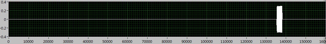
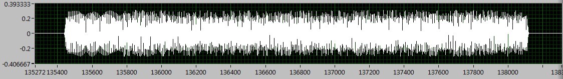
As shown in the following figures, the signal I want to deal with is between 130000 to 140000, if I Zoom, I can see the useful signal is between 135400 to 138200. The question is how to extract the signal in the area?
I tried the sub_NoiseEst_And_Chop_Shell.vi in the example of Packet_based_link also, but this Subvi seems to be a bit slow. Can someone give me the best advice? Thanks in advance!
I'm working on something similar, but have not had time to fully develop.
My idea was to use an envelope detector (low pass filter) and then use a detection of energy VI on the envelope.
Here is where I left
-
How to generate arbitrary waveforms FRO meter
Hello
I have a problem in the generation of the wave as shown in JPG below. Need to generate digital waveforms 2
1. with the help of counter0 - digital waveform will be with pulse 60 (58 - good pulsations and 2 empty pulse)
2. with the help of Freqout - digital waveforms should be to synchronize with a 40 pulse signal 2 signal should be high for then 5 impulses.
I tried model digital generation with Boolean 2D table convert to digital waveforms. But somehow, I couldn't have expected waveform.
If someone could help me in this problem.
Thanks in advance
Vijay
FREQ Out is not able to generate either of two waveforms - it can only generate continuous pulse trains. In fact, even one of the complete M-series meters would be unable to generate your "Signal 1" - you must use the 2nd meter to the signal from the door.
Supported boards of series X buffered output of the counter and could therefore be used to generate a waveform. You can use Freq Out yet, but the X series boards have also 4 full meters if this should be enough resources such as Freq Out is not necessary.
Best regards
-
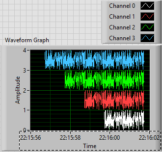
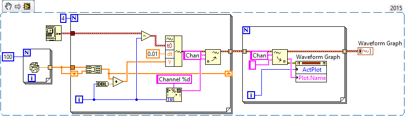
I have a chart single 2D out a conditional of a loop indexing output such that over the rows of the table are not the same size. -Basically, they have different starting and ending points and sizes. -Not so concerned by the endpoints, because as soon as I get correctly starting points, everything shows fall in place.
The challenge is that when I try to have the variable t0 (start time) for each line, the wave of construction vi form would always keep each line at the same starting point.
I used the approach bundled with success (the cluster approach ensures that each waveform starts at different times according to the guidelines of my t0 defined for each line) but then I'm not able to get in the channel names I could make using the graphical approach (wave generation) waveform.
In essence what I get here, I'm losing here.
Because I don't want one of my mentors, Bob and Altenbach have fed up with me I have attached a vi this time

Attached VI shows a combination of the two attempts (first with the waveform graph) and then with the graph of cluster
1. with the first (graphical waveform), I get my channel names as you wish, but the alignment of the wave is not correct.
2. with the second (graphical cluster), the alignment is good, but I can't do the names of channel in the chart, even if they are present in the cluster.
I read some reviews that mentions that attributes can be displayed with waveform and data Dynamics (not clsuters) so I guess that's why.
I saw another report indicating the start time for a waveform 1 d will always remain the same for the rest lines defined for the first line even if changed for the following lines in a loop.
So I guess my question is: what is the way around questions like that?
First of all, let me be the first to the congratulate and thank you for finally posting a code! I'm not 100% certain I understand your question or your code, but I have an idea, perhaps, of what you want to do, so I wrote a little VI who made something simple that could be relevant.
You mention waveforms of different lengths and beginning at different times. You also want everyone to have a unique attribute (although I'm not sure what you want to do with the attribute). So, I did the following:
- Generated an array of 100-sample random to represent one second of a waveform.
- Created 4 waveforms on this 100-sample basis. The first waveform (channel 0) is just these 100 points. The second, 1 channel, is the concatenation of string 0 with the base of 100 samples, or a waveform "double". Channel 2 is 1 string concatenated with the base, and channel 3 is 2 string concatenated with the base.
- In order to trace the four channels that they rest 'on' the other, the waveform has the number of the channel added to it. Channel 3 is 3 + (4 copies of the basis of 100 points), a waveform 400-point random centered around a shift of 3.
- All channels have dt value 0.01 (but I guess I could have varied, as well).
- To make the channels start at different times, I started channel N N seconds before channel 0 (by subtracting the index of the loop, I, T0).
- For each channel, I created an attribute called "Chan" equal to "Channel N" (where N = 0, 1, 2 or 3, as the case may be).
This is the plot that results. Scale X is the absolute time value (no Date) using the 24-hour HH: mm
 S format. You can see that the plots are 1, 2, 3 and 4 seconds of time, and are offset from each other by a second. I used the trace attributes to change the name to the respective attribute.
The code to do this is very simple - I almost don't need to show it, because I think it is completely described by the text above, but this is here:
Now, it was not that much faster that some of your previous posts, when you refused to your postcode, "guess us" what you wanted (but not to not correctly guess), you tried to "push" us in the right direction (still refuses to post code), and no one seemed very happy?
Bob Schor
-
How to record measured analog data on the PC?
Hello
I am a beginner in the real-time hardware. I have the cRIO-9024 controller and the cRIO-9112 chassis. I have a few questions:
(1) I can't see the examples because Labview 2009 shows that The NI Service Locator is not running. I just installed Labview 2009. How can I solve it?
(2) what is the best way to filter the measured analog data? There are hardware module filtering or I have to use Labview tools as filters pint? I would like to read data to the time step 1 Ms.
(3) how can I save measured analog data on the PC? I tried to use 'write to file measured', but he did my program slower and I couldn't get my 1 mS of a cycle. Can I use cRIO-9024 memory somehow and after when the programme is complete to save the files to the hard drive? Maybe it would be faster?
Thanks for any help and examples, whether it would be possible.
Hello Rodzynek,
If you do not have the FPGA module (or just for now) the solution you gave with the filter would be OK. Place a second loop for file IO (and possible your communication to the user Windows interface) would be a good idea. Do not forget that you are using on the function of file create the file path represents the drive of the controller cRIO (which is mostly a c drive). You can send via FTP to the RIO DC (using the IP address) and have a look at the files.
A suggestion to get this file programattically is that the cRIO controller sends the file name of the Windows user interface (after the closing of the record), with the Windows user interface, you can use the FTP functions in Labview to get the measures file.
Best regards
-
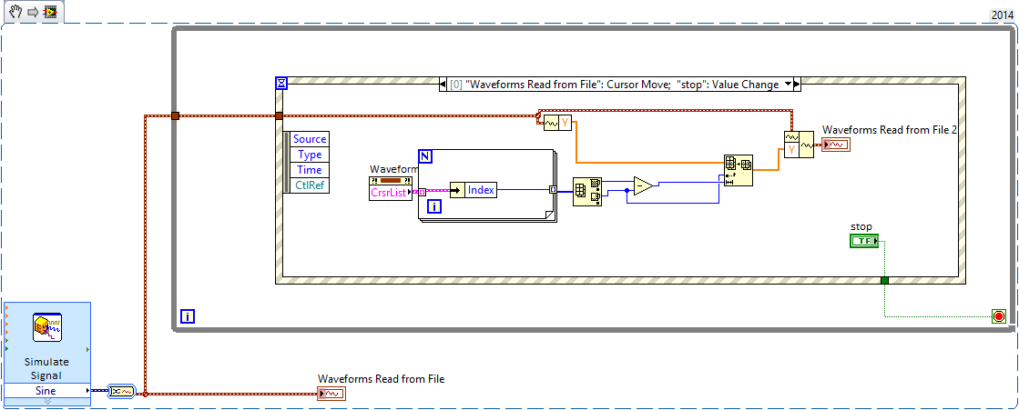
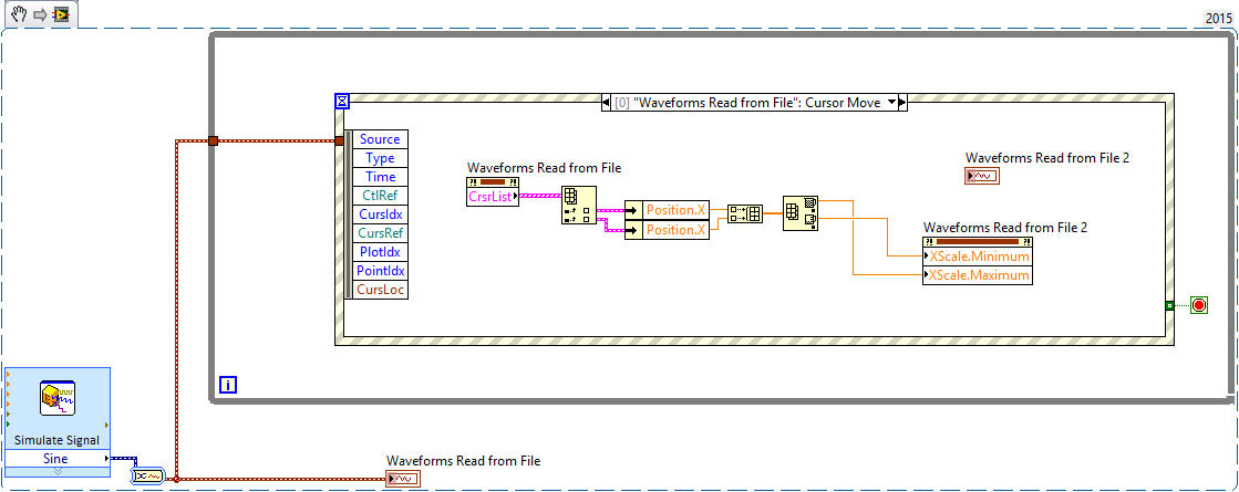
How to synchronize the start time in the waveform graph
Hi all
I just find a solution in the forum to select the data you want in a grap of waveform with cursors, however, I don't know how to synchronize the time of beginning of waveform for the second graph. How can I extract start time of the waveform with the index data?
Something like that? It is a bit gross, but is what I think you're asking, should be able to use it as a starting point.
The Max - Min is to make sure that the cursor is always valid.
-
How to use an internal counter of the cDAQ-9172 for measure PWM and generate the frequency?
Hello
Requirement of my project is to measure 6-channel PWM and generate 5 frequency channels.
Suggestion of engineer OR bought cDAQ-9172 chassis and NI 9423 (8 DI correlated) and NI 9474 (8 correlated DO) for this requirement. I have a few questions
Article:
1 > what should I know to customize my CompactDaq 9172 chassis
http://zone.NI.com/DevZone/CDA/tut/p/ID/9367
I know that this way to synchronize the physical support 32 correlation system pin o for housing 1-4.
=> I'm not really sure how to use these channels synchronization support.
2 > using internal counters on one NOR cDAQ-9172 as a sample for other tasks clock
http://digital.NI.com/public.nsf/allkb/ADFC4DD8C9690232862575B70079FBD4
I know that I can change the ownership of the physical channel so I can get 2 meter outside the frame 6 and 7.
=> I do not think that this solution will be me because I can use only 2 counters with this method.
Could someone tell me please how to fix my project requirement? How to choose the setting for DAQmx screws?
I have experience with measure the PWM and generate the frequency, but with separated against only.
Best regards
Thang Nguyen
Hey Thang.
AHA... for this, you can use the channel property node.
See you soon
Lab
-
How can I display only a part of the scale in the waveform graph
This is the first time I try to use the waveform graph, since now, I used the table of waveform.
The reason why I moved to the chart, it's that I need cursors.I have 2 problem
the first: in the diagram, the graph moves when I add a new data and the scale of the x-axis stay the same size, in the right size I always saw the new data. How can I do that with waveform graph?
Second: How do I say Labview to the day I click on the graph, I need that because when move graphic I lose the day, and to make I need to zoom out, I drag the imprecateurs.
All this must be done programmatically. The LabVIEW graphic accepts tabular data, not only as the table and the graph doesn't have the ability to retain the previous points, like the story of a graph. You will need to retain previous values and then continually update the graph with the old and new values to get a shift register "chart as behavior. Cursors should be written programmatically re of each iteration, since you rewrite the entire graph.

Maybe you are looking for
-
Yes, I know that I have an old iMac to 7 years with a CPU of the stone age.Yes, I know that the OS X 10.4 is exceeded.Yes, I'm aware that my version of Firefox is no longer supported.Yes, I know that some of the plug-ins are outdated. But the system
-
It's a 17-minute video, but except that there isn't anything special about the file I'm trying to save. What is going on?
-
My Media Player 11 says I need a "codec".
I have Vista, and my Media Player 11 won't play CD because he says that I don't have the required "codec" installed. However, I can't find one who will install. I have already installed a patch/file that is supposed to fix the file installation probl
-
DynDNS is showing the WAN IP of my E2000 (192.168.0.3) who is assigned as the intellectual property by my DSL modem. I used to run a client on a PC running on my home network, also with no visibility to my ISP assigned dynamic IP that somehow updat
-
taskbar, icons in notification area
(1) in the notification area of the task bar, volume and network icons are missing. How to add? (2) the task bar hides automatically, how to keep it always appearing on the desktop?