How many samples timed on a single digital output line
Hello
I want to output a pulse of arbitrary shape train on a single digital line (for NOR-USB-6229). The goal is to control acceleration, live performance and deceleration of a motor not not.
To do this, I'm writing an array of samples ' Dev1/line 2' ('writeArray' in the code below), a single sample per millisecond. However, I see everything that happens on this line. What I am doing wrong? The following C code:
int numSamples = 3000;
TaskHandle taskHandle;
DAQmxCreateTask("",&taskHandle);
DAQmxCreateDOChan (taskHandle, "Dev1/line2", "", DAQmx_Val_ChanPerLine);
DAQmxCfgSampClkTiming (taskHandle,"", 1000 / * samplingRate * /, DAQmx_Val_Rising, DAQmx_Val_FiniteSamps, numSamples ");
DAQmxStartTask (taskHandle);
samplesWritten of Int32;
DAQmxWriteDigitalLines (taskHandle, 3000, true / * autoStart * /, 100, DAQmx_Val_GroupByScanNumber, writeArray, & samplesWritten, NULL);
DAQmxWaitUntilTaskDone (taskHandle, 100);
DAQmxStopTask (taskHandle);
DAQmxClearTask (taskHandle);
All responses will be very appreciated!
Petro
Peter,
It is not that these devices do not have access but rather (from the Manual X 622): "the digital subsystem has no its own dedicated internal synchronization engine. Therefore, a sample clock must be provided another subsystem on the unit or an external source. "Choices would include: Any PFI, RTSI, HAVE sample or convert clock, AO, Ctr n out internal and many other signals sample clock.
If you current solution works well you should do!
Tags: NI Hardware
Similar Questions
-
How much noise is expected on 6353 digital output lines?
I'll send a signal to pass a set of relay reed with the port on a pci-e 6353. When the line is low, the noise is ~ 10 mV. When it is high, the noise is ~ 30-40mV. The noise seems to be done through the signal lines in the reed relays.
What is the level of noise that is expected?
I intend to move to electrostatic armoured relay. Meanwhile, the filter mentioned in the manual of 6353 only apply the digital input?
Thanks for the help
Hi Nico,
Here are the results of my 6353 running a DO loop to HAVE (high and low)
So, at the logical level above I see noise on the order of what you described. Logical low my noise is significantly lower. I guess it depends really how noisy your mass plan is and what does the Board of Directors, as well as what is connected to it.
* Edit, I suppose a more legitimate test would be to use an array 2 to measure the output voltage. I still think that this test has some merit by showing that little noise on the line is not uncommon.
In any case, since the lines are outputs digital, the spec just says that they must reach TTL voltage levels (< .4v="" for="" a="" logic="" low,="">2.4V to the logic of the top). I did all the typical numbers for the noise on the lines, but what you see does not seem unreasonable. Have you tried the bypass capacitors by adding to your relay by chance?
Best regards
-
Finished samples timed material vs single-point: different speed?
Hi all
Although I had several questions about this request before that separately have been resolved, there is one last thing that remains difficult.
Shortly:
My application acquires data from 2 analog and synchronous inputs on 2 channels of analog output.
There is a trigger stop set on a PFI-pipe with a single switch. To make of this
I had to switch from single-point over acquition timed work material.
This set works very well when I read not less then a 100 samples once with a sampling of 1000 Hz. frequency (when I go below a sample of 100 to read--> E-200279)
Ideally, I would like to read about 10 samples with a sampling frequency of 1000 Hz.
However, using single-point timed equipment acquisition I can easily do that without a problem. Even just reading
a single sample once with a sampling frequency of 1000 Hz does not have a problem. But impossible to use the block of relaxation of reference as a signal to stop with this setting!
Question:
For me, there are two solutions, but so far I could not work on one of them:
(1) build a stop trigger in an single point of timed material acquisition
(2) change something in the acquisition of finished so that I can read faster.
Any suggestions, what causes the difference between the two speeds to be able to read the data and a way to solve it?
Thank you
Mark
Mark,
I mocked how I think I would like to address the issue and tied it to the top. The general idea is that we use HWTSP for our analog I/o and counter looking edges on our signal "stop". Each iteration of the loop, we check if we saw the stop signal. If we have, then we write zero for the output channels and stop the loop. If this isn't the case, write us the data of your comments, we have calculated. I've added some comments on the block diagram that I hope are useful. I have currently no any material of series E share, so it may not work properly out of the box, but I thought it would point you in the right direction.
I offer this precaution:
Windows is not a real-time operating system. Therefore, it may take the liberty to give as much CPU time to other processes or applications as he likes. As a result, it is likely that you will not miss a few samples (IE, your loop will not go faster hardware issues are examples of clock). I configured DAQmx must return a warning you when this happens.
Hope that helps,
Dan
-
How many virtual machines on a single HBA?
Hi all
I understand a VI3 environment for a client, but I doubt if HBA will be a bottle neck for the performance of the virtual machine. I would like to know how much minimum I should recommend? Two enough a primary and another for failover? can you tell us the load balancer for HBA? I read that we can have several number of VMs communicate via a single HBA, however, there will be performance problems? Can anyone share their experiences and their recommendations?
Thank you
Rahul
I've not seen HBA as a bottleneck, especially with the 4 GB HBAs now commonly available.
I only dual port HBA in our blade servers and servers of U 1, I ran 2 x single port HBA.
Main SAN issues, I've had have been a doubtful avalanche Transceiver and a motherboard fault on a Server Blade.
Otehrwise HBAs themselves were enough sound that's why I am not too concerned about the unique dual-port HBA's on the blade.
A lot of the design is subject to redundancy and how much risk / single points of failure, you are willing to tolerate.
-
Generate the pulse signal signle on the digital output line
Hello
I am now writing a program using c# and DAQmx.
I have a NI PCI-6514card and I want to send a signal for half a second to a single line of output.
I know how to write online by using the DigitalSingleChannelWriter object, but I want this signal, disappear after a period of time.
Thanks in advance for your support.
J.. Gasser
One thing is certain:
C:\Users\Public\Documents\National Instruments\NI-DAQ\Examples\DotNET2.0\Counter\Generate Pulse\GenDigPulse\cs
It is on Vista.
On XP, I believe that the path is:
C:\Documents and Settings\All Users\National Instruments\...
-
How many devices can I have on my iCloud account
How many devices can I have on my iCloud account. Sometimes I find my apple TV new does not work and it is not the network, and not applications.
Looks like 10 devices (source - how many devices can use a single account iCloud?)
-
How to secure the wiring of digital output BNC-2090
Hi, I'm working on using the digital output of data acquisition to control the digital DAC input, but I have a problem on how to fix the wiring for the digital output of the DAC. When I plug the cable into the hole, it is vaguely related. Any suggestions on how to fix the wiring are appreciated.
Thanks in advance!
It is a spring terminal.
Try to push in the orange tab with a screwdriver while pushing in the thread. Release tab to release the wire, and it must grab and hold the wire. It may be a case involving Orange instead of push. You should be able to understand.
-
How can I write a digital waveform to the digital output (traditional DAQ)
Hello
I use a NI 6023e, PCI, with 8 digital outputs. I generated a digital waveform. How can I write for a specific digital production line now?
I only have Labview 7, so I can't use DAQmx.
Thank you very much
-
How to configure the digital output of the pci terjeta 6023E in LabVIEW 8.5?
Hi, I have a card PCI-6023E and LabVIEW 8.5 and I need is to configure the digital output on the card, but did not.
My idea is to get a port of digital data on the map and control by a pwm small dc motor.
I wonder what are the modules with which you can do.Hi skudero,
Probably the web page tracking and the attached example will work.
PWM in software timing using a digital output line
Concerning
Charley - NIB - SR 1368189
-
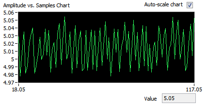
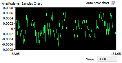
Well, I thought I had everything figured out, but we have finally had time to go to our lab and test it and there seems to be a problem with the output digital here. I'll look at what's the point of this VI, then describe the problem
Analog input is entered and analyzed as digital outpt is sent several lines (3). The digital output is used to send a single, user‑defined delayed pulse TTL with other instruments like triggers. I put this program to create an array of digital waveforms for each channel, each of them are of the same length as the analog input. '1' is inserted in the appropriate place in the table, in lieu of a value of '0', creating the required table. This table would be written on a digital line (1 channel, samples of N). Three of these subVIs are used here, so three signals various tables are created and writtin in its respective lines when the program runs, the analog input seems to work very well, but that a single digital output is executed. I need all three lines to write simultaneously.
I use a USB-6221 with LabView 8.2
I have attached all the files needed to run this program, and if the 'LabView programs' folder is saved on the C drive, I think that the paths of the files must be correct.
Thanks in advance
Hi Chris,
Hello and I hope that your well today.
Thanks for your updates.
I think that my being better if we start from the beginning.
1 could you try the example Correlated Dig writing with Counter.vi from the Finder of example of NOR?
It produces output meter as the time base for the digital output - to get clocked at digital output. Don't you see the waveform being printed on your outings that match the graph of digital waveform on the front panel?
If not, try to use one of the other examples, as Scripture Dig Port - this is a single VI just to send a single value for each digital line. If this does not work, there is a connection problem.
2. If we got this far without problems, then the next part would be to change the waveform so that you could write the data that you want to...
The digital waveforms can be made a boolean table, then using the array of Boolean DWDT to Digital.VI to convert into the type of digital waveforms. The waveform will have X number of samples. Therefore, at each clock pulse, you will produce 1 sample on each channel. So if you set the rate for 1000 and the number of points to 1000 (samples) it will display the waveform on a second. (as his continuous the DAQmx will make a loop through the buffer and start out of the waveform again).
Note, have you seen the palette of digital waveforms? It is located under waveforms and has more vi like the Boolean DWDT to digital.
Please let me know how you go.
-
clock calendar - digital output
Hi all!
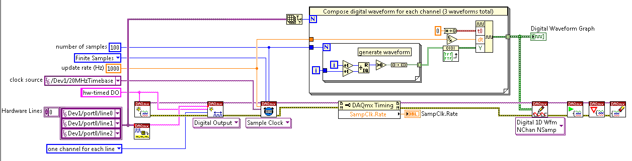
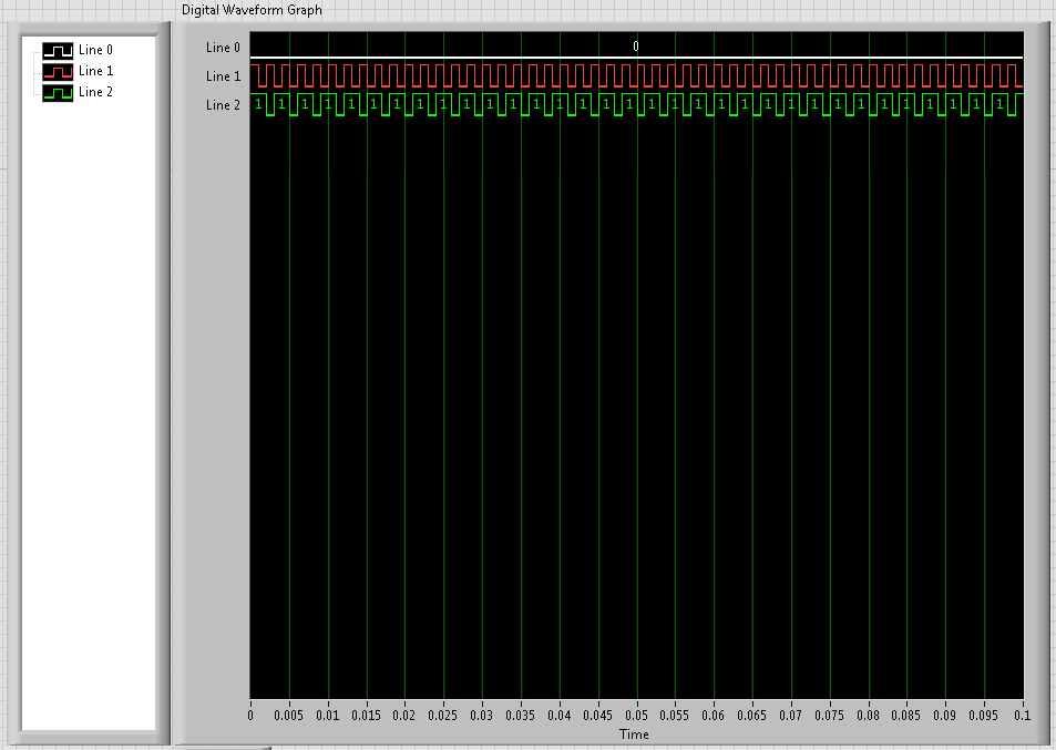
I need timing equipment impliment on a few digital output lines. That's what I have so far:
I didn't get an oscilloscope for her yet, but I'm fairly certain that it works. Please note that in this example, I use a PCI-6115. I have 2 questions:
(1) make what I do look reasonable at a quick glance?
(2) I'm kinda mistified by the entry of clock source to the example of the clock function. The analysis that I read just still confuses me. I understand that the clock is what dictates the sequence of material. I do not understand how to choose the appropriate clock source correctly. More specifically, in the above example, I've only had the program work when I chose "20MHzTimebase". What is c? Why this work?
When I try to select ' Dev1 / / SampleClock ", I get the following error:"attempted to perform a route when the source and destination are the same point."
When I try to select "Dev1/PFI0" or "RTSI0/DEV1", I get a timeout error in the wait_until_done.vi--> it does not appear that the waveforms are executed.
That means the PFI and RTSI acronym for, and why they appear as options when you select a source of the clock? Furthermore, why have they not worked as a clock source?
I would be very grateful to anyone who could clear things for me a little. Thank you!
Have you read the http://digital.ni.com/manuals.nsf/websearch/01C075FB9478F94A8625786A007435BA? manual The definition of PF and RTSI are here. They are designed using external clock signals. You have the choice of using the internal clocks of analog output (20 MHz) or external clocks. If you do not connect the RTSI bus or PF what, whether you have no clock so no data will be output. Selection of as source does not work because it is not a source. You provide a source for it.
-
How to send a pulse only to analog output
I send a function rect through to the ao, thorugh the transmitter transducer, then a receiving transducer through AI. Although I'm kind of a signal, I can see that there is something wrong. What I think is happening, is that the pulse is transmitted continuously while I want it to be sent once. of the received signal, waiting for the signal to reach 0.2/1500 s as the medium is 0.2 m in diameter and the speed of the sound probagation through it is around 1500 m/s. So, with these considerations, I have the following questions:
1. How can I configure the wizard daq output to send only 1 rect function
2. read permanently or for a period of time
I have attached the output and input along with a photo of my VI signals
Thank you
Hi Macane,
For a unique configuration of generation/acquisition, you would set your DAQ Assistant to finish instead of continuous and calculate how many samples is your only impulse you send. For the acquisition, you can configure a finite acquisition of trigger reference analog where it will begin to capture after your signal is received, or if you do not want a triggered acquisition, you can set the number of samples to acquire. For example, finished task sampled at 1 kHz to 2000 samples would correspond to a second acquisition 2.
You can configure all the wizards within the express VI data acquisition by double-clicking the VI. I hope all goes well!
-
take the digital output USB-6001 always high or low in c
Hi all
I am new to the NI DAQ interface. I have a USB-6001 and I am trying to use this device to control some flowchart in C. What I want to do is:
* set digital output lines with high and low intensity and change their status as needed (in C).
I tested the device NEITHER Max--> Test panels and found that the device is capable to do that. Then I try to do in C. I have checked hace examples and function I use is one called "DAQmxWriteDigitalU32". I have problem in the understanding of its input parameters. I tried something with my own knowledge, but it does not work as I expected. Here is a test I did:
data uInt32 = 1;
Int32 wrote;
TaskHandle taskHandle = 0;
DAQmxErrChk (DAQmxCreateTask("",&taskHandle));
DAQmxErrChk (DAQmxCreateDOChan (taskHandle, "Dev1/port0/line7", "", DAQmx_Val_ChanForAllLines));
DAQmxErrChk (DAQmxStartTask (taskHandle));
DAQmxErrChk (DAQmxWriteDigitalU32(taskHandle,1,1,10.0,DAQmx_Val_GroupByChannel,&data,&written,));taskHandle = 0;
DAQmxErrChk (DAQmxCreateTask("",&taskHandle));
DAQmxErrChk (DAQmxCreateDOChan (taskHandle, "Dev1/port0/$line0", "", DAQmx_Val_ChanForAllLines));
DAQmxErrChk (DAQmxStartTask (taskHandle));
DAQmxErrChk (DAQmxWriteDigitalU32(taskHandle,1,1,10.0,DAQmx_Val_GroupByChannel,&data,&written,));I just want to set ' Dev1/port0/line7' and ' Dev1/port0/$line0"at a high level, but only ' Dev1/port0/$line0' answer me. The second parameter of the DAQmxWriteDigitalU32 function is numSampsPerChan. If I replace (currently 1) with a higher value, such as 100, I see that "Dev1/port0/line7" sends a number of 1 output, then back to 0. So I guess that the problem is just that I understand not all parameters for the DAQmxWriteDigitalU32 function. Is someone can you please tell me how I can set up a line of digital output 1 or 0?
Thank you!
Hongkun
Hello
I finally find a way to do it! The feature works very well, and my problem was not set the data value to write correctly. It seems that if I want to write a 1 to the port0/line1, I put "data = 2 ^ 1" rather than "data = 1", because by default it is the second bit of the port.» Similarly, "data = 2 ^ 7 ' high level to port0/line7. I find that this setting is surprising when you want to control an individual line. It seems more reasonable when you control the whole port. In any case, is to solve the problem!
Thanks anyway!
Hongkun
-
USB-6211 - digital output not supported?
Hi all
I can't use the USB6211 device port... I use daqmx with Delphi7 API functions.
First of all, I tried this:
DAQmxCreateTask('', @TaskDO);
DAQmxCreateDOChan (TaskDO, PChar('Dev1/port0'), ", DAQmx_Val_ChanForAllLines);
DAQmxWriteDigitalU8 (TaskDO, 1, 1, 1, DAQmx_Val_GroupByChannel, $FF, @written, nil);I had an error in the DAQmxWriteDigitalU8:-200012 (= digital output not supported). (???)
OK, I tried to disable autostart option based on DAQmxWriteDigitalU8 and insert a 'manual' start in the code:
DAQmxCreateTask('', @TaskDO);
DAQmxCreateDOChan (TaskDO, PChar('Dev1/port0'), ", DAQmx_Val_ChanForAllLines);
DAQmxStartTask (TaskDO);
DAQmxWriteDigitalU8 (TaskDO, 1, 0, 1, DAQmx_Val_GroupByChannel, $FF, @written, nil);
DAQmxStopTask (TaskDO);Now, I got the same error in DAQmxStartTask:-200012 (Digital Output not supported, once again). (?????)
I don't understand.. 'Digital output not supported "? USB-6211 has 4 lines! What is the problem?
I want to just turn on and off the lines from code...
-Cs George-
Well, finally I figured out...

Here is the solution:
DAQmxCreateTask('', @TaskDO);
DAQmxCreateDOChan (TaskDO, PChar('Dev1/port1'), ", DAQmx_Val_ChanForAllLines);
DAQmxWriteDigitalU8 (TaskDO, 1, @dummy, 1, DAQmx_Val_GroupByChannel, @bitmask, @written, nil);Digital output lines are on port1! Corrected parameter.
And the part of the interface of DAQmxWriteDigitalU8 had to be changed (in nidaqmx.pas).
I don't know why, but the AutoStart (dummy) parameter in the DAQmxWriteDigitalU8 function is ignored: function always starts task automatically, regardless of the value of autostart. But this isn't a problem for me.-Cs George-
-
NEITHER 9205 digital output configuration with DAQ Assist
Hello
I have two NI 9205 Analog Input Modules which I have configured to read from each of their 32 channels. I used the DAQ Assistant help generate the vi which contains the task out - DAQmx event and also the DAQmx Read vi.
I used the Wizard twice, once for each module 9205 and then put the playback functions in a sequence structure so that only read would be carried out at the same time. It all works very well!
Now, I want to add in the code to wait in a loop before all loop containing playback functions, so that the user can press the GUI to send a logic 1 to the unit under test, and after it is sent immediately starts collecting data.
The DAQ Assistant Help does not recognize the module 9205 when I try to set up a task to write a digital output. 9205 a 1 digital output so why is the wizard does not recognize this? I also tried to create a task manually, but I got stuck.
Someone please help. I can reach the source if needed, but I thought that the descriptions above were sufficient.
Thank you
Gary
Hello
You are right it shows a line in this user manual, and in fact, you have found an instance where an important piece of information was left out of the documentation. This digital output line is actually only available when you use a cRIO chassis. It will not work with the chassis for the acquisition of data compact 9172. Here is a knowledge base that explains it. I'll also go ahead and file a request for corrective measures so that this note be included in the next version of this manual. Thanks for the comments.
Chris
Maybe you are looking for
-
I signed something where I will get an email from them when a certain offer arrives. The problem is, however, I get a lot of spam on my email address, so I have disabled notifications to send with the exception of my VIP. The other problem is that I
-
Should I get a Macbook Pro or an iPad Pro to use for the next two years while I do my A-Levels?
Hi all! So I am currently doing my GCSE, I'm looking to my future at school aka Sixth Form (A-Levels). I won't be carrying massive files that weigh tons and can easily broken / lost files kept in the breast, as do the current year. However, I checked
-
setting has been changed, so I have no header on all screens. How to make a comeback?
-
Best Option to support multiple versions of an application
We have 50 + versions of an application we need to sustain indefinitely for legal reasons. Today if a previous version is required, an administrator must uninstall the current version and reinstall the old version on the user's PC. We want to simplif
-
Passport for blackBerry lock screen stuck
my passport for blackberry is blocked on the lock screen and does not allow me to enter my password once it comes to enter the characters appearing on the screen keyboard. I tried to restart and reset the phone via the volume and power buttons, but h