How to acquire the signal to very high sampling frequency
Hello world
My name is Luke Ho. I am trying to acquire the signal with Labview (Sthelescope). The signal comes from sensor acoustics, then filters and amplifiers to adapt to ADC rank (0 - 5V). Thus, the maximum frequency of the signal is 40 kHz.
According to the Nyquist theorem, I sampled at least 80 Khz signal.
Is there a sampling frequency devices like that? or y at - it another way of better? I used the Arduino before, but it was about 10 kHz.
I need your advice.
Thank you all and have a nice day.
holucbme wrote:
Thanks for your recommendation
But is it possible without USB Data Acquisition, it is quite expensive for me.
This is the cheapest option to NEITHER. I tried to look for options to other companies, but more I found in the same price range, or not answering is not your condition of sample rate.
Tags: NI Software
Similar Questions
-
How to extract the signal from the waveform of my power level designated?
Hi all
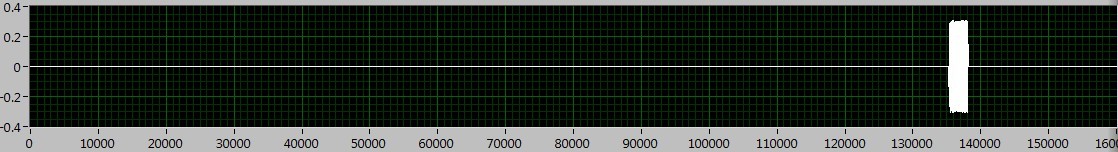
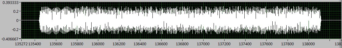
How can I extract the signal of the waveform accroding to the power level? I read the Trigger & Gate .vi, but this vi retrieves the signal duration. I want to extract the signal depending on the power level.
As shown in the following figures, the signal I want to deal with is between 130000 to 140000, if I Zoom, I can see the useful signal is between 135400 to 138200. The question is how to extract the signal in the area?
I tried the sub_NoiseEst_And_Chop_Shell.vi in the example of Packet_based_link also, but this Subvi seems to be a bit slow. Can someone give me the best advice? Thanks in advance!
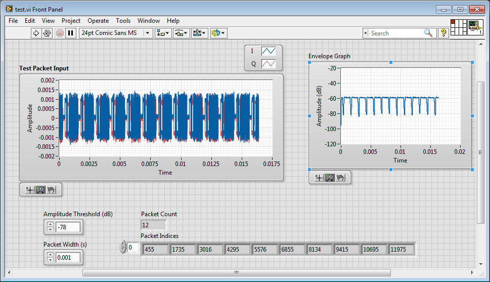
I'm working on something similar, but have not had time to fully develop.
My idea was to use an envelope detector (low pass filter) and then use a detection of energy VI on the envelope.
Here is where I left
-
I am facing a problem with the beep.vi. I have a DAQ program, which acquired the signal and compare it to a threshold value. When a signal is out of range, a Visual and sound alarm has occurred. I use the VI beep.vi to generate the sound. Everything works fine except the sound alarm. It gives the table 1 d of type mismatch. I tried to fix this by placing it in a box structure. But it still does not work. If someone could help? Please find attached my VI. Best wishes to all visitors to the Forums of Discussion OR.
Ihab El-Sayed
published here: http://forums.ni.com/t5/LabVIEW/Playing-sound-based-on-exceeding-a-threshold-value-1D-array-data/m-p...
-
How to find the Web sites of high quality backlinks?
Original title: how to find quality backlinks?
Updates on the algorithms research of new google forward a site spammy that build a bad backlinks. But how to find the Web sites of high quality backlinks? Could we must spend a lot of money to get their links?
Please help me.I want to increase backlinks to my site
Hello
I recommend you contact Google support for assistance:
http://support.Google.com/bin/static.py?hl=en&page=portal_groups.cs
Hope the helps of information.
-
How to acquire the catalogue of convenience store to operate ms fix?
Original title: attach it to microsoft
How to acquire the catalogue of troubleshooting I need to exploit the ms program fix
Hello
1. what Microsoft Fixit you trying to use?
2. what convenience store catalog are you referring?
If you are having problems using Microsoft Fix it tools, I suggest you to send your request in the Microsoft Fixit forums for assistance.
Let us know if you need help with Windows related issues. We will be happy to help you.
-
How to trace the signal acquired against the clock all the time fixed by using Graph XY?
Hello
My goal is to trace the signal acquired against the clock all the fixed time dynamically. In General, it is like trace the waveform of the signal against the clock in a graph, but don't keep the recent 10 min waveform. My current approach is to get the timestamp by a VI and the express VI to use XY graph to make the plot. The result keep all data in the history which is not what I want. My question is that how to achieve my goal?
Thank you very much
Hao
One way to show the last ten minutes of data is to use a graphic instead of a graph. Set the size of the history of the ranking for the number of samples you acquire in ten minutes.
If you want to use the graph XY, you will need to manipulate the data yourself. If you don't want data from the last ten minutes and you want to throw all the old data, set up a circular buffer sized to hold the ten minutes of data. Once the buffer is full (after the initial ten minute break) adding a data point removes the oldest point. Make the buffer of a 2D with X data table in a line and the data Y in the next line. A queue with loss can be used in recent versions of LV to implement a circular buffer. In older versions, a driving force would be a good choice.
Lynn
-
How to acquire the generated signal?
Ladies and gentlemen, I am a novice in LabVIEW even if I practice solving problems more or less difficult, I got NOR cDAQ-9178, possess an entrance connected with output channels and after a plan of work on the signal acquisition and production separately, I decided that I could successfully combine the two plans and get the system of acquisition of generators. Hell I didn't know it wouldn't work. There are probably many things im doing wrong in this case, so no finance or support directly with the .vi is attached to the message would be so appreciated. Thank you.
One thing I think is that your generated frequency is not suitable with #S and Fs you have configured. Try #S = 10 k and Fs = 100 k.
-
How to select the signals from the output of a DAQ assistant
Hello!
I am a new user of Labview 8.5 and I work with a USB-6210. I have two different instruments connected to the same USB device, half of the channels are used for the transducers of pressure where I only need reed and record data, while the other half are associated with TCD detectors where I need to perform an analysis of the signal to get and save the data. I'm in the first stage of construction the block diagram, once I have defined each of the signals that its correspondent of channel using the DAQ assistant, I need to select and separate the signals coming from sensors of pressure from those who come by the TCD detectors, before that I can continue to draw the block diagram. I am using the function select Signal, but I don't know how to do this. Can you get it someone please let me know at least in which manual, I can find a good explanation? I have read the getting started and the LabView user manual, but they have not been very helpful so far.
Thank you!
I fixed it. As you say, I had some mistakes in the thread, but it's working now. Thank you very much for your help! It was very useful.
-
How to test the signal strength of an Airport Express, which extends a network?
I am trying to understand how my Airport Express is actually help to expand my network, and if I should move somewhere different. Any help would be appreciated!
Current situation: my base station is an AirPort Extreme in our apartment computer room; for the internet, which is plugged into the wall. The wifi network is extended in the living room via an AirPort Express (version 7.6.4). There are on the same cabinet as the AirPort Express to Apple TV. The Airport Express has an optical cable connecting to a sound bar (which has an additional HDMI connection to the TV).
I don't really know if the AirPort Express Terminal, he does something useful. The network is set to be extended, best I can tell: Airport Extreme network Mode is "Create a wireless network", and network Mode of the AirPort Express is "extend a wireless network. But still, the wifi on my iPad and iPhone signal strength seem to fall much in the living room. Apple TV usually broadcasts music from my desktop computer (in the computer room) well enough, but if I try to play music from my computer via the Apple Express at the soundbar, the connection is terrible and fall. (Which could be a problem with wifi, or could be an aging Airport Express question, could be a cable problem or might be a sound bar problem...)
An example of what worries me: if I go to the Airport utility on my iPhone and a glance at the Airport Extreme, it has 4 Wireless, including Apple TV clients. But if I look at the AirPort Express, there sometimes a client wireless (iPhone), but never shows the Apple TV: even if the Apple TV is about 30 cm of the Airport Express. It's as if the 30cm distant to the Airport Express connection is weaker than the connection of two-rooms-distant Airport Extreme, but I am probably wrong that.
In any case, is there a way to test what speed is through the AirPort Express, compared to through the extreme? I tried to use applications like CloudCheck on my iOS devices, but those only measure the speed of my network, and it is unclear whether or not he uses the Extreme or Express.
Thanks in advance and all apologies if I used (almost inevitably) 'Express' when I should have used "Extreme", or vice versa, somewhere at the top.
One way to see the strength of the signal is the Alt (option) key while clicking on the WiFi icon in the menu bar.
But you see not directly related to the airport of arrival. Also the Airport utility does not give much information.
You can see a lot more with the free app (Appstore) called "WiFi Scanner".
The problem could be that the place you have chosen for the Airport Express can be better: it should be somewhere in halfway (in force) between the Real and where you sit with the iPad/iPhone.
-
How to calculate the signal / noise from the graph?
In my current project, I read a periphera voltage signal. the signal lead noise even after filtering. So, to identify the necessary data, I averaged the signal.
I have attached the file with an image of graphics. In this graph, the recorded data are drawn black and medium online graph is plotted in red. Now, I have to calculate the ratio of signal to noise to specify with these peak values. How to do?
As the signal passes through zero, be careful in the way you set the signal / noise. For sinusoidal signals, that ratio is defined as the RMS value of the noise (the signal with the desired sinusoidal signal deleted) divided by the effective value of sinusoidal component.
First of all I would like to subtract the average value of the raw signal. The difference is the noise. You can set the signal / noise. A RMS calculation might work. If you have a mathematical model for the desired signal, a fitting for this model can be useful too.
Lynn
-
How to acquire the values of CFP 1800 use FP read via RS 232?
Hello
We have an application in which there is a provision of the redundancy of the system. By redundancy, I want to say that I have a CFP-2120 and a host PC. Both are accquiring real-time AI module using concept shared Variable values. Each of these variables is linked with a particular channel of the Module & will acquire the data automatically. Initially when the system is Ok, the PC acquires data from the PSC 1800 using ethernet. Now, suppose that the ethernet connection has been lost, now that the PC will not be able to acquire. At this point, I want my PC to acquire data from the PSC 1800 using RS 232. In this case the binding of the variable with channel won't be of such use. I think that in this case, what I can do is to accquire data .vi FP READ and update the variable by plugging the variable for each channel.
What else will be the solution. Can someone tell me if my colleague and I are on the right track or if the best solution is here, please share with us.
The move will be highly appreciated.
Thank you best regards &,.
Samriddh Sarbalhi
Hello
You're going in the right direction for creating redundancy for you system controller PSC.
Here is the link for system redundancy with two components:
http://zone.NI.com/DevZone/CDA/EPD/p/ID/5997
I hope that this should help.
Anuj Bhansali
AE
NEITHER the India
-
How to display the signal on a waveform graph in Labview Signal Express?
Hello
I want to display a signal in Signal Express 3.0 in a "waveform table", but don't know how to do it and I think that it may be impossible?
In Labview, there are two ways to view data, a 'waveform table' or a 'waveform graph. The great thing with 'picture of waveform' is that it allows you to set a length of history and you can see the data move to the left (option graphic strip) that samples are recovered. It works perfectly.
In Signal Express I can only select "Graph XY" or "Waveform curve" by doing a right-click of the mouse, but I can't select "table of waveform. Is it really true that it is not possible to view data in a graph of waveform "with Labview? (1 analog signal during streaming, 100 samples to read at the rate of 1 K)
Thank you in advance,
Enrique
Hi Enrique.
You are right that there is currently no graphic waveform in SignalExpress. The thing nearest you can join, is saved data under a log and then he looks one when recording (which I know this isn't quite the same interactive behavior).
For your last comment, you wrote 'waveform curve', but I guess you meant 'picture' here as well.
Sorry about that. We recently received this request, then perhaps in a future version.
Phil
-
Compound of button: how to return the signal of a component to another
Hello, I am quite new in BB10 development. I have a question:
I'm doing button image with text. My idea was that I will create custom component consists of two components:
ImageButton
Label
Label will be the button Image and contain customizable text
It basically works, but it seems that swallows Label click signal and it is not propagated to the ImageButton control. I tried to put
setFocusPolicy (FocusPolicy::None); for the label, but it does not work.
My questio is: how to do it correctly? Should I capture signal clicked() on the label and send it back to the ImageButton control?
Thank you
Tom
Hello!
This can help you!
Refer to overlap touch policies in
https://developer.BlackBerry.com/Cascades/documentation/dev/touch/touch_propagation.html
OR
See how to create the source for the Timer class
I think so
The control signal can be connected to the signal of another control.
-Rezé
-
How to optimize the signal from my router?
When Im in a room on the ground floor, hence my router is in I can barely get a signal on my iPod Touch and the Xbox! I was wondering if there is a way to optimize the signal from my router so that I won't have no connection issues... PS. sometimes resetting the router help, but not as much as I'd like.
Try these settings.
Access the routers admin pages. Connect via a wired computer to 192.168.1.1 with your browser, the empty user name, the password "admin" (everything that you change too).
Disable UPnP. Under settings wireless Beacon interval 75, RTS and Fragmentation threshold to 2304. Try channel 1 or 11. Save the settings and reconnect.
-
HAVE high sampling frequency of trigger
Dear community
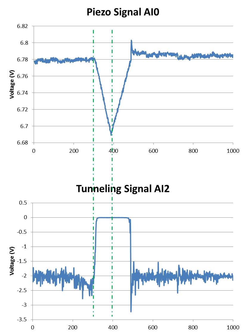
I am using a microscope to tunnel effect from here feeding two voltage signals on my map of acquisition of data USB-6212 (Labview 2013 SP1). A voltage signal is the voltage applied to a piezo in the microscope (AI0). This signal drifting slowly over time and it is noisy. The other voltage signal is a tunnel current is converted into a voltage (AI2) signal (see attached photo):
Ideally, I would like to record the two signals between the lines dotted in a .txt file whenever the event of tip in the top image rises. This should be about every second during a day.
So far, I've written a VI that calculates the moving average of the piezo signal and if the piezo voltage exceeds a certain percentage of the average running it fires a command 'Save as file'. The VI works well for a frequency of 100 Hz, but when I go to 20 kHz, the trigger does not work properly. I am also only watching a lot of a number (in this case, 1000) and if there is a trigger signal in these samples of 1000. So if there's a signal around 0 or 1000 I cut and split into two files that I want to avoid.
I don't have much experience with Labview and probably broke every rule of design in the book.
My question is if there is a smarter way to automatically back up the signal between the same dotted lines at high frequencies of sampling?
I thank very you much in advance!
Hi Mario,.
I rewrote the portions of your VI to improve performance (we hope). No need to three queues. No inquiry unless there is a trigger occurs.
I'm confused by the outbreak that seems to detect the edges of the piezo signal high side, even if the tip is in the negative sense. I modified this logic (eventually) get a threshold top-side of the signal of tunneling.
It is unclear what might happen to 20 kHz. The example shows a constant 1 kHz sampling rate and 1 K samples treated by loop. If the sampling rate is changed to 20 kHz, then the loop will have to run to 20 Hz in order to keep up with the acquired data (@1 K samples per read).
I hope that the joint allows VI (not tested).
Maybe you are looking for
-
I have a HP pavilion a4313w number model. I have only one VGA port for a monitor. Is there a way I can plug a HDMI TV instead of my monitor?
-
CTRL F4 closes Firefox, cancel all downloads
When he has that one tab, using Ctrl-F4 closes firefox and cancel all downloads. This happens when the erasing of a few tabs and pressing Ctrl F4 a little too long. ALT F4 gives a warning that firefox download yet, just Ctrl F4 isn't fair. CTRL F4 is
-
Journal of faxes on hp6500 e709n
I try to print only the sent fax log and increase the number of transactions at more than 30. Calls currently all receipts going to the fax has hit the journal. Help
-
Warning: you are connected to two computers.
I was working in my account to windows live hotmail and when I tried to open an email (at least, I think that's what I was doing at the time). I got a pop up message that says I was logged into two computers and my email was not available and I have
-
Hello My system crashed because the pci.sys file. Can you help me? https://www.dropbox.com/s/zvno60rz2l3fyj8/041514-31559-01.zip Thank you. João Vieira