How to break a digital input continues to arduino into pieces
Hello
Basically I have a shift register parallel-input series output connected to an arduino UNO, which is interfaced with labview. The exit of shift register is fed into pin Digital arduino with eight inputs 1 or 8-0. what I'm trying to do is to assign each bit of the digital pin of the arduino to a LED on the front panel in labview. For example, if there are four 1 and 0 to read the arduino pin ovens then four of the conduit must be on and four must be turned off. Any help would be grately appreciated.
Thanks in advance.
You already have the table Boolean number. This is the part I was worried to find you. Table of Index to get the Boolean individual out of the picture. And Index table is expandable, you only call him once in this case. Expand it just to have 8 items and wire up your LEDs.
Tags: NI Software
Similar Questions
-
How to combine several digital inputs for playback?
Hi comrade Labview users.
I just started using LabView and I am very new to it. I know him understand how it works and you have something to work, but I need to be more effective.
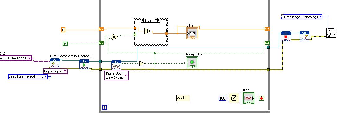
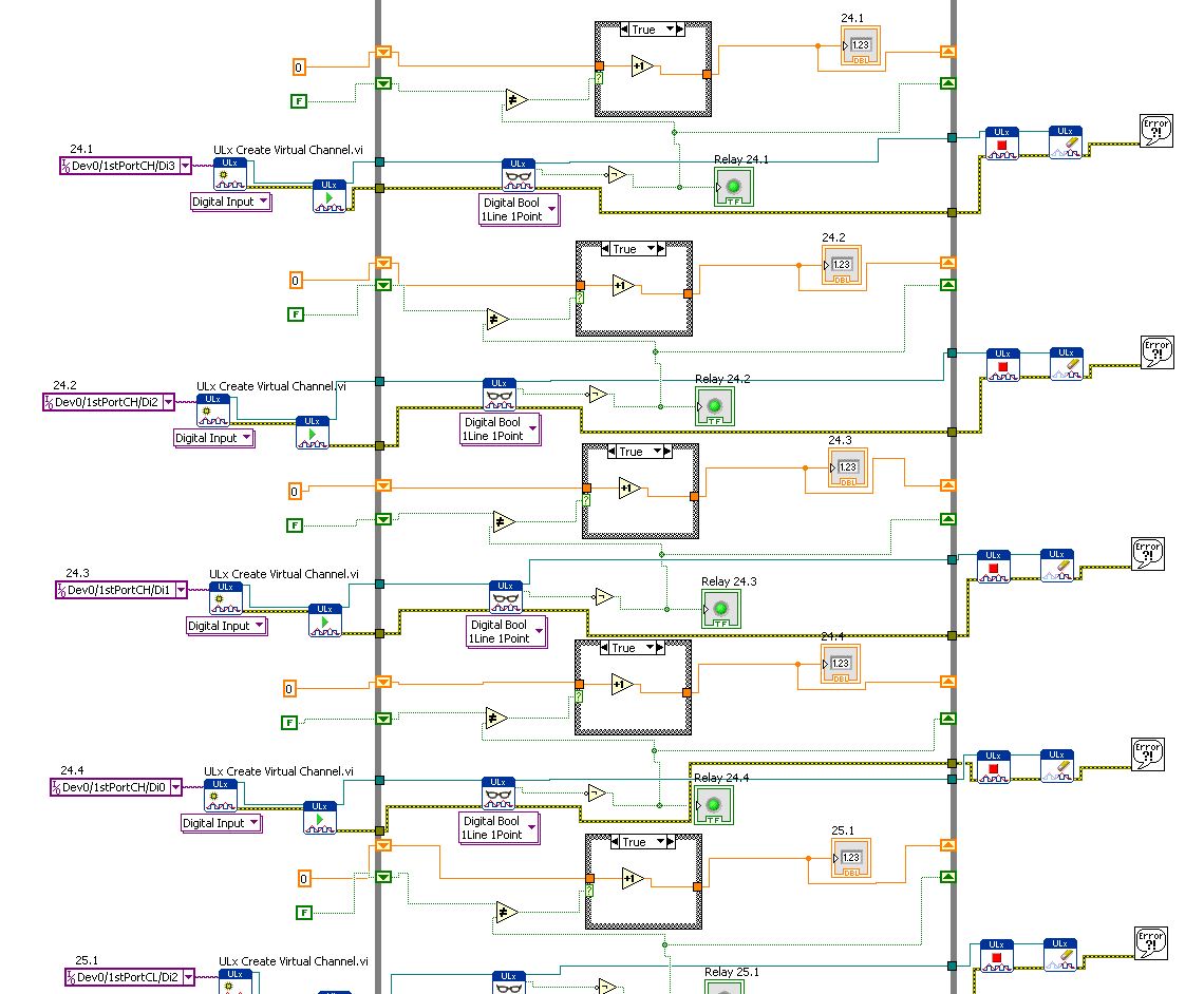
I use DIO96H - USB DAQ Measurement Computing, which includes 96 digital inputs. I use the DAQ to acquire the activations of relay and record the number of times the relays flips.
Basically, I created a digital input read and then copy & pasted 95 times... it works but I know that's not the best way to use LabView.
How can I change the digital input (Di1/1stPortA/dev0) in multiples so that it iterates through all 96 channels without copying and pasting the same pattern over and over again?
Leon
You have the correct polymorphic instance for playback? Once again, for the material OR it would be a NChan Read. There should be a similar choice if I remember correctly.
-
How to count the digital inputs of the sensor
IImsmd MicrosoftInternetExplorer4 normal 0
I use a PCI 6221 OR-DAQ device and I want to count the total number of times that a sensor is activated. The sensor is connected to a digital line.
Tadhg salvation,
If everything you want to count the number of times where the sensor is activate, the best way to ensure this is to use a line from the meter, in the case of the 6221 try pin 37, Cnt 0 Src/PFI8. And take a look at the example of counting code digital Events.vi that you can find from the Finder example under Hardware Input and Output > DAQmx > Counter measures > County Digital events.
Alternatively, if you use a digital line, just read the line, and if the sample is true variable increment held in one register at offset, similar to the Count.vi DI attached
I hope this helps.
-
How to use the digital inputs? (PCI-6010)
Hello
I have a PCI-6010 card and I tried to use a pulse generator in one of the channels of entry without success, I m using panels of 'Test' in MAX.
How can I configure dthe hardware to make it work?
Thank you
APOs instalar a ultima versão labview refazer tudo bem mouse conexoes as w.
Any forma, obrigado pela a definition.
-
Hello
How can I avoid digital input from the user in a form (text) PDF field?
I want the user to be able to enter any character, except 0,1,2,3,4,5,6,7,8, and 9
Without displaying an alert or a sound, I just need any input digital diseable.
Thank you.
Enter this code in the script custom typing your text field:
If (event.change) = event.rc (/ \d/.test(event.change)) == false;
-
How can I set up a digital input task to read continuous samples?
I am trying to create an exclusively digital task that will make digital readings at a rate timed by the material using a PCIe-6509. However, when I try to put the task timing as follows (which works on a PCIe-6509), I get the following error:
Requested value is not supported for this property value. The value of the property may be invalid because it is in conflict with another property.
Property: NationalInstruments.DAQmx.Timing.SampleTimingType
Required value: NationalInstruments.DAQmx.SampleTimingType.SampleClock
Possible values: NationalInstruments.DAQmx.SampleTimingType.OnDemand, NationalInstruments.DAQmx.SampleTimingType.ChangeDetection
Task name: DigitalInputTask
State code:-200077
The relevant parts of my code are:
public class DigitalInputReader: IDisposable
{
public DigitalInputReader()
{
dataReadyHandler = new System.AsyncCallback (DataReadyEventHandler);daqmxTask = new DigitalInputTask();
daqmxTask.Configure (Globals.NI);daqmxTask.Control (TaskAction.Verify);
daqmxTask.Control (TaskAction.Commit);daqmxReader = new DigitalMultiChannelReader (daqmxTask.Stream);
}public class DigitalInputTask: task
{public DigitalInputTask(): {base ("DigitalInputTask")}
public virtual void Configure (NiConfiguration niConfig)
{
<= niconfig.digitalinputs.count="" -="" 1;="">
{
String physicalChannelName = niConfig.Device + "/ port" + niConfig.DigitalInputs [i]. Port.ToString () + "/ line" + niConfig.DigitalInputs [i]. Channel.ToString ();
String nameToAssignToChannel = niConfig.DigitalInputs [i]. Name;DIChannel ch is this. DIChannels.CreateChannel (physicalChannelName, nameToAssignToChannel, ChannelLineGrouping.OneChannelForEachLine);
c. InvertLines = niConfig.DigitalInputs [i]. InvertLines;
}
var signalSource = "";
This. Timing.ConfigureSampleClock (signalSource, Globals.MachineSettings.SampleRate, SampleClockActiveEdge.Rising, SampleQuantityMode.ContinuousSamples);// Globals.MachineSettings.SamplesPerChannel);
}
}The last call to Task.Timing.ConfigureSampleClock, it's which throw errors.
Of the options available, or SampleTimingType.OnDemand or NationalInstruments.DAQmx.SampleTimingType.ChangeDetection provide the same precisely timed calls that I am familiar with the analog input interruptions.
How is it possible in a digital task? I mean, it seems that I could set up another task to do call by material for the production of a clock signal and use the ChangeDetection synchronization mode, but this seems a bit complicated for what should be easy to do. What Miss me?
Update: I thought about it. You cannot call ConfigureSampleClock when the digital input card is a device of 650 x, because these devices have any automated examples of clock. They are configured to run in mode default finite samples. You must make all sample synchronizing with these devices in the software.
Be cautious, however, because the .NET timers ensure they put any faster than their scheduled interval. In practice, they are usually 5 to 10 ms slow by tick. This means that if you want to read samples every 100 ms by sample clock, you'd end up reading all 108 ms samples. All counters based on the elapsed time and number of samples would be away after a few seconds of it.
Instead, you must do one of four things: write a doggone driver that runs in ring 0 and interfaces with the PCIe card in the required interval (i.e. on NC, not you, in practice), tolerate the inclination of the clock, use a multimedia timer as an interruption audio or video that is more likely to respond to the correct interval, or , my solution, an accurate clock allows you to set the interval of the timer. I wrote the following code to the timer:
var CorrectiveStopwatch = new System.Diagnostics.Stopwatch();

var CorrectedTimer = new System.Timers.Timer()

{
Interval = targetInterval,
AutoReset = true,
};
CorrectedTimer.Elapsed += (o, e) =>
{
var actualMilliseconds =;Adjust the next tick so that it's accurate
EG: Stopwatch says we're at 2015 ms, we should be at 2000 ms
2000 + 100 - 2015 = 85 and should trigger at the right time
var StopwatchCorrectedElapsedMilliseconds = newInterval +.
targetInterval-
CorrectiveStopwatch.ElapsedMilliseconds;If we're over 1 target interval too slow, trigger ASAP!
<=>
{
NvelIntervalle = 1;
}CorrectedTimer.Interval = NvelIntervalle;
StopwatchCorrectedElapsedMilliseconds += targetInterval;
};I hope this helps someone.
-
How can I measure the time between the two edges of successive increase, using digital input...
Hello
I'm trying to measure the time in seconds between each two successive rising edges on a digital input.
So far I managed to detect the rising edge, increment a counter at each rising edge and take the time during which the increase is edge
all I need now is subtract edge currently rising from the previous era of edge rising to calculate (T), which can be 1/frequency and display in real time for the user.
but I do not know how to do this

Can someone help me please!
Note: while I am in a position varies between 200 ms - 2 seconds
-
How can I measure the time between each two successive increase edges, using digital input?
Hello
I have tried two measure the time in seconds between each two successive rising edges on a digital input.
So far I managed to detect the rising edge, increment a counter at each rising edge and take the time during which the increase is edge
all I need now is subtract edge currently rising from the previous era of edge rising to calculate (T), which can be 1/frequency and display in real time for the user.
but I do not know how to do this
Can someone help me please!
Woah!

Sorry Apok, but your code becomes much too complicated and salty. I don't think that all records to offset or Boolean conversion/operators are necessary at all.
If you want to measure the time between two keys so it's another (much less complicated) way. It simply records the time when press button in a registry change, then compares the two.
-
How to count the pulses with digital input on 6351
Hi all experts in Labview,.
I just got my USB x series 6351 and it works fine, but I certainly lack of labview skills to use it to its full potential.
I would like to read digital pulses with several digital inputs and count the number of pulses each T interval in time. All impulses that I entered on any edge of the clock are not synchronized and can occur at random times during the tests. Basically I have an oscillator of square waves can I modulate the frequency. I don't want to use the meter as inputs as I'm limited to only 2 entries (if I use the option 2 input meter for metering of pulses or frequency). The input frequency can range from 0-1 kHz and goes 0 - 3V. So not too fast, and I shouldn't make too many mistakes trying to get the count of pulses and then back out the frequency in accordance with article ni.com on counters.
I would like to read the 8 digital input channels and get the number of impulses for each channel. I searched high and low for help online but can't find examples that have been useful. Anyone have any ideas on how to go or direct me to a resource? Thank you very much in advance!
Are you worried about getting the number as a physical operation timed? It would be nice to acquire a digital waveform and then postprocess on it to detect how many events took place? I've attached an example that shows how you can accomplish this. It reads a digital waveform and then uses a detection of crete VI to determine how many pulses occurred. Should be a few adjustments to your particular signal. The VI I use seems to count events twice (probably count each edge), so counting it gives should be reduced by half in order to work.
-
DAQmx: set up a digital acquisition continues with start and stop trigger
Hi all
I write because I can not find a solution to my problem.
As written in the title, I just want to do an continuous (continuous sampling) a digital line. The fact that it's a digital line instead of an analog is no big deal, I guess. I want to start the acquisition on a rising edge of digital trigger (PFI0 for example) and stop acquisition on a trigger too (forehead down on the same signal (PFI0 even then) or a new front amount). This way I could precisely control the time of acquisition or of the start or stop other devices.
Since this is a digital acquisition, you need to do first "something": create a fictitious analog input task and get the clock back to the digital input. I setting this analogue of the task to start on a trigger. It works but I can't find a way to stop it on another trigger.
Do u hav no idea how to implement it?
Finally I have not found an easy way to break cautiously the VI to wait for a trigger (in case you want to start an acquisition with different settings for example). Do you use the task to Abort or is it better to set a deadline to playback digital channel VI until the outbreak occurs?
Any help would be appreciated!
Thank you
Config: LV 2010, latest version Daqmx and USB card or 6251.
Hi Chris,
One way is to use counters as Kevin described. For me, it's usually easier to create the dummy task that has the timing engine (as I HAVE), but it depends on what resource you have on your board you will not need
 .
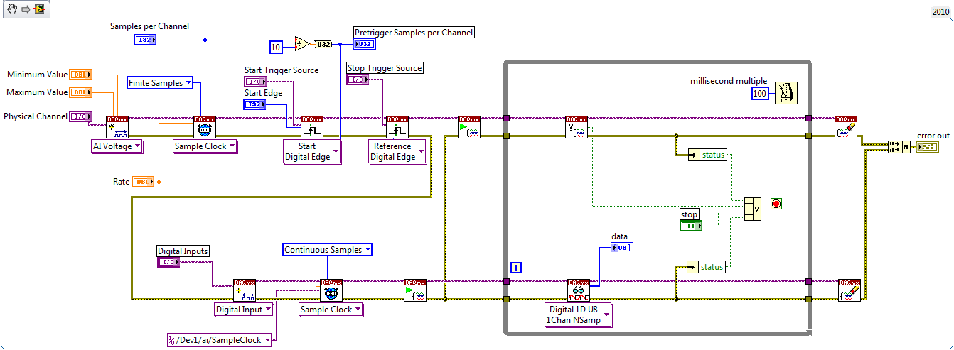
.In fact, the example is the same thing that you need to measure continues - just what you need to do is remove the counter part and replace the trigger reference to be external (your stop trigger).
with this approach, you should be able to do the continuous measurement - I noticed that you need DI - in fact with few changes you should be able to use this example. DI does not have its own timing engine, that's why you should use the external sample clock. If we use the example to create dummy HAVE to provide the sample clock, and we start DI task until we start to HAVE fake, then we can get pretty much continuous clock which begins start trigger and stop the trigger of reference.
Take a look in the change - once again, I have not tested, but logic seems to be OK.
with sincere friendships.
s9ali
-
How to get Dolby Digital 5.1 sound on Qosmio?
I wonder how to sound Dolby Digital 5.1 Qosmio. Whenever I play an original DVD movie, all I can get is Dolby Prologic 2. Have a link with DRM? I use Thomson mini plug opto cable. Home Theater receiver accepts digital input but does not have 5.1 sound. The movies that I download with DRM removed HD forums gives the same results. Where is the problem?
Thank youHello
The line line and S/PDIF audio headset uses the same output.
It is possible to connect the audio/video receiver via SPDIF optical cable.
http://www.LaCie.com/products/product.htm?PID=10739 -
Problems with the digital input/output
Hello
I have a little problem with my card PCI-6143. I would use two connectors digital one as a starter and one as an output. Now, I have the problem that I do not know how I address them. The input works as I want but not the output.
As an example. I call my channel output on this name: Dev1/port0 / line0:0.
With this call, the application works very well. If I change the output channel to Dev1/port0 / line4:0 I get an error that the values can be read and 0 and 1 are valid values.
I hope that the call is right, I wrote that out of my head.My questions are. Is it correct to call a single digital channel with this name?
I'm not sure because I do not understand what these means 'line' and if I allocate really single channel or more.
The second question is, can someone give me an example of how I assign two digital channels (how to address them)?
I know it's maybe an easy question, but I can't seem to get it corrected.Hope someone can help me.
Best regards
The syntax that you use is intended to select several channels: the numbers are the initial and final channel in a subsequent channel list. Thus, written Dev1\port0\line0:4 means 5 lines are included in the read/write (FWIW written 4:0 has the same effect). It is redundant but good writing line0:0, which means a single line, but you can write to Dev1\port0\line0 which is simpler.
This is a help page on this topic.
-
Hello
I am relative new to LabWindows.
I have a program that starts when I press a button. The program controls a motor. Now I press a button on the motor and the program must cease (Safty Stop). The button is connected to a digital input on my card (PCI Express 6343). Now, I have the question, how do I program the interruption? I know not how do in CVI (controls the digital input whenever the program runs).
I hope someone can help me.
Best regards
The starting point must be to look relevant examples that NEITHER provide:
ReadDigChan - ChangeDetection.prj
and
ReadDigChan - ChangeDetectionEvent.prj
However, I must advice against using a PC as a "Safety Stop". As a general rule, the PC are completely inappropriate to the core functions of security, unless you follow the standard IEC 62304 relevent to the letter. Tip: it's hard to do with a PC. To implement safety functions such as emergency and interlocks stops you buy much better a specialist dedicated safety relay and following the instructions of the manufacturer. If life-threatening energy (either electric or medcanical) may be present, then consult a professional engineer.
-
Hello
After reading everything that specifications and manuals, I decided to ask a general question.
In the data sheets, user guides I've read, in general, there are two warnings for DIO:
-Do not connect the outputs digital circuits which operates above the limits.
-Do not drive the line with tensions outside its operating range.
Generally speaking they tell me I need to know when dealing with output and voltage when dealing with entries. So I have this question, can I wire a power supply for digital inputs directly without exceeding its "beach of normal operation and without any protection circuit? In fact, my feelings, this is not possible. But why certain documents produced clearly mention that the impedance internal inputs while that of others is not clear those? How can I determine if I can connect a signal directly to an entry (for example USB-6525 indicates a current limiter circuit, but I don't see a clear explanation in the datasheet USB-6251)?
As long as the input voltages are within specified limits, no damage will be the DAQ hardware. Logic devices often have two lines of non overlapping input, one for low input and high input. If the input voltage lies between the beaches, the performance of the device can be unpredictable. Also, check your power supply to make sure that this doesn't not exceeding when turned on or off as that could exceed the DAQ limit.
Lynn
-
Hello world
I use an NI USB-6501 and I'm trying to understand how to read the entries.
I used this card to generate output using the example vi write Chan digging, it works fine.
Now, I'm trying to use the example of reading dig Chan vi to read an input voltage. But it seems that, by default, the map reads 5V (a 1 logic) as entered on each pins, even if nothing is connected to them. I tried to connect the output to the input, use a relay to see if it detects a change in the entry, if we send a voltage or not, but it changed nothing. It still reads 5V anything.
Can someone help me understand how to be able to read an entry? This problem has happened to someone else?
Thanks in advance.
Frédéric
If you dig through the data sheet, you will see that there is a 4.7kOhm shoot all digital inputs. So with the floating inputs you will get a high (logic 1).
As Dennis have already said, wire your digital output directly into your digital input. So everything that you set the output that you will read on the entry. I don't know what you do with a relay.
Maybe you are looking for
-
How can I remove a category that is unwanted on the homepage of iPhone Safari? I click on "Safari" and popular, new, Google Maps, Yahoo, Wikipedia are still there. Now another site, I have visited is also displayed. How can I get rid of him?
-
P6-2380EA: what graphics card is compatible
You are looking to play Elite space sim and need to know what graphics card is compatible and works well.I am naïve.
-
OfficeJet Pro L7580 - 'no Scan Options '.
I have an Officejet Pro L7580 - I just started getting the 'Scan Options no' when I try to use the scan on the Panel button. Also, I can not open the HP Solutuion Center software to scan from computer. I tried the HP cat help... worthless and unins
-
Help, why no device after installing win 7 on new E5-411 showing?
Recently, I brought an E5 Aspire-411, in Thailand, with a Linpus Linux operating system. I installed my favorite OS Win7 x 64. I managed to install the hardware drivers. The strange thing is that there is no bluetooth device in Device Manager. Is thi
-
Hi all I have configure 802. 1 x with ACL downloadable on IOS version 12.2 (52) SE and 12.2 (55) SE4, I found that there is a different behavior. On 12.2 (52), I need to create a default ACL and apply to the ACL on the interface. On 12.2 (55) SE4, th