How to change the frequency of sampling DAQmx during execution?
Hello guys. I'm using LabVIEW in the measures of the frequency response function. My application requires the sampling rate to change according to the frequency of the signal during execution.
I tried to do it with a "structure of the event" and it works well when I change the rate manually via the front control but it backs do not work when I set up the sampling frequency to vary automatically (just a frequency sweep). Photos below:
Why not the structure of the event feels the change in the value of "rate"?
Thanks in advance for your help.
Lucas
Hello
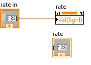
In "automatic mode" to change the sampling rate, the calculated rate is written in the local variable (as illustrated in the code). Structure of the event does not change value in the local variable as an event.
In order to make the structure of the event to recognize the change in value of an indicator such as event: write the new value to the property "Value (Sgnl)" corrosponding node to rate indicator (see figure below). This will make the structure of the event accept the value change in the indicator as event.
Note: Use architectures such as producers and consumers for such applications, which makes the application readable and expandable.
See rear queries if any.
Tags: NI Software
Similar Questions
-
How to change the frequency of tracks in multitrack session?
Hello!
I have a question and hope you can help me!
I created a session of multtrack with 2 tracks. How can I change the frequency of them? I mean each track has a frequency of differrent and I use hearing CS6.
Please help me!
Thank you very much!
If by frequency you mean sampling frequency so you can edit the audio file by double-clicking on the item in the multitrack and then right click once you are in the edit mode and select 'convert sample type"and you can change to say 48 k say 44.1 k or something else.
If you mean, by frequency, pitch so you can do this by again taking the clip view editing and in the menu select Effects > time and Pitch > Pitch Shift
-
I have a vi that:
-Locate the USB port that RS485 communication device is connected
-sends a command to each sensor
-reads a response from each sensor
-performs a calculation on the answer
-saves the response to a file of measure
I used a flat sequence to query each sensor. I am trying to find a way to modify this vi in order to increase the frequency of sampling on the sensors. Currently, it takes 2000ms for question 4 sensors and write tot the measures file. Anyone have any ideas on how to speed up by programming? I am concsidering on the purchase of a device USB DAQ (USB6000) and rewriting of the vi. I was wondering if there was some tweek I caould make on the vi.
Thank you!
I meant put the time-out on the line, then the reading will be either timeout after 200ms or read the 2 bytes. Whichever is faster. Then deletes this 200ms waiting you. I have attached your vi to show you what I wanted. I did not notice that it is a hardware or wither then you might want to look in the data acquisition functions. It will clean up your code and are very easy to use.
-
How to change the frequency of images for an Actionscript program?
Hello
I read that the Timer() calls accuracy depend on the frame rate of the movie, they play in (which makes sense because they are Flash, after all!). I'm working on a project in pure ActionScript 3.0 and I wonder how I change the pace of this project, I don't mind to increase it to about 50 fps so the Timer() calls can be pretty accurate.
The base class, it is executable, currently in this project is an extension of the Sprite, but that could change if necessary.
Thanks in advance!
David
It is the Stage.frameRate property. You must Access the scene via a DisplayObject. There is also a compiler option: by default-frame-rate
-
How to measure the frequency of NOR-DAQmx RPM tasks
Hello
I'm trying to measure the frequency using the NI DAQmx task and then convert it to a RPM if possible.
I have the following material available to me.
I have a block SCXI-1327 terminal, as well as a 6289 PXI multifunction data acquisition Module SCXI 1126.
I wired in a mag ai7 sensor on my 1126 and then of the passage of an object metal I get a range of 6-8, so I am able to read the mag sensor.
What I'm trying to do is somehow convert this analog measurement a RPM using the NI DAQmx task only.
Any help would be appreciated.
Hi, smooth,
Yes, you would select linear, then put in the result of this calculation of the slope.
The Manual recommends a minimum frequency of at least 15 Hz for setting low range. This card is not really designed to measure the frequency for a single pulse over a long period of time.
The number of LAPS down (assuming one pulse per turn) that we recommend that you measure with the 1126 is so 900 RPM. If you need measure low revs, and you cannot increase the number of impulses per turn, you could consider either read the signal as an analog waveform, or if it's a digital pulse, using a counter to basic task. In this way, you can use any method you want to handle the situation where there is only a single pulse in a long time.
-
HOW TO IDENTIFY THE TYPE OF ACTIONSCRIPT CODE DURING EXECUTION
Is it possible to get the version of actionscript in flash movie that is to say, if AS1.0 or AS2O or AS30 during execution?
It is possible to detect the execution if a movie is of the type AVM1 and AVM2.
AVM1 means all the movie clips targeted before the Flash Player 9. [AS1 or AS2]
AVM2 means video clips focused on Flash player 9 or higher. [AS3]
The following code detects the version of the clip.
var img = _loader.getChildAt (0); _loader is a loader loading an external swf file object.
If (img is AVM1Movie)
{
Alert ("avm1 movie...");
}
on the other
{
Alert ("avm2 movie...");
}
I don't think you can distinguish if the movieclip is AS1.0 or AS2.0. because, at compile time, the AS2.0 code gets converted to AS1.0 code.
-
How to measure the frequency of sampling (s/s) in LabView FPGA?
Hello
I am trying to find a way to measure the sampling frequency (s/s) during which I read from analog input in LabVIEW FPGA. I know that the sampling frequency is specified in the data sheet of the module HAVE, but I want to measure in LabVIEW.
Any suggestions?
A screenshot of the example code would be greatly appreciated
Hey phg,.
If you have some time loopand in this loop, you export a sample by iteration of loop via an I/O node. You can't out two samples on the same I/O node within an iteration, it's always one!
So if your loop takes 1 second to run you have a sampling rate of 1 Hz output. The same goes for sampling of entry. How long your loop takes to run can be calculated as explained above.
Samplerate [s / s] = 1 / [s] while loop
-
How to lock the frequency of sampling for 5673 and 5663
Hello
In general I try set the transmitter and the receiver. It seems easy to lock the carrier frequency, but no matter what I do, I seem to have a drift in my sampling frequency (order of 1 ppm).
Is the sampling clock in the digitizer 5663 linked to the same reference like OL clock? ... I didn't know that I needed the mechanism TClk here since I don't care for delay...
Any thoughts are greatly appreciated. Here are some details.
I use the 5673 as transitter and 5663 as receiver. I noticed as follows:
1. when each use a "reference clock Source' = OnboardClock I have a carrier notable offset to the receiver (for example carrier 5.8 GHz has ~ 7 KHz offset) and that's fine.
2. when each use a "clock reference Source" = clock, with the physically attached chassis PXI, I see no delay perceptible carrier to the receiver.
3. what 5673 uses 'Reference clock Source' = OnboardClock, using 'Reference clock Source' 5663 = ClkIn (ClkIn/Out physically attached), I see no delay perceptible carrier to the receiver.
-
Try to set up the e-mail function analysis. Using the button on the printer, I go as far as to go to outgoing SMTP and then I get an error message that the user name or password is incorrect. I don't know what is the right user name or password.
I want to get rid of whatever information incorrrect and redo information. Nobody seems to understand the problem. Any help?
Please use the Forum from HP Support. I brought your question to the team within HP. They are likely to ask for information from you to get your information or product serial number. Please search for a private message from a contact HP identified. Also, remember not to publicly display (numbers series and information).
If you are not familiar with messaging private forum please click here to learn more.
Thank you
Omar -
How to check the amount of memory used during execution of the program to save data in the table?
Hi any idea how to read or check use all memory space by accumulating the table with the data?
My program works like this: -.
(1) values are acquired and displayed on the table
(2) the values are acquireduring the next event and appear in the next row in the table.
(3) and this continues...
Please notify
Thanks in advance
Hi astroboy,.
You can use 'Flatten channel' to get the size of your data.
Mike
-
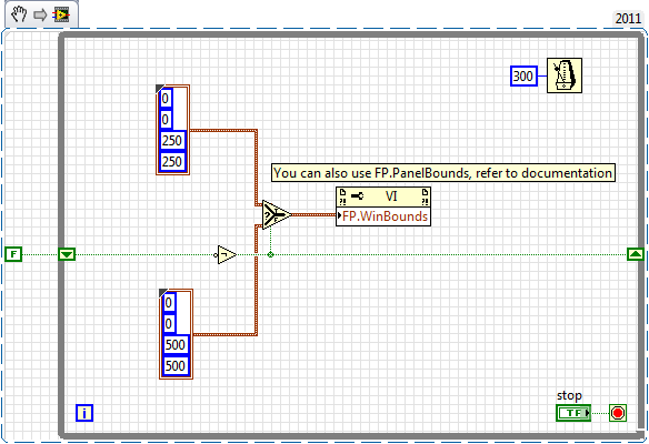
How to change the runtime of height and width of the front panel
How to change the front height and width during execution. Basically, I want to decide height or width according to some parameters that I'm in the moment of execution.
Ed johnsold was first

-
Change the frequency AO AO DC voltage scanning scan?
Hi all
I am very new to labview, but find the forums and examples extremely helpful. I probably spend 50 + hours to familiarize myself with tutorials and general information, but I am at a point where I need your help.
I'm unable to change the example "AO frequency sweep" found here (see custom_sweep_1.VI) to allow me to sweep the voltage. My instinct is that I don't need of the ' waveform buffer generation VI ' and that I should be able to remove the associated entries since I'm only interested in a sweep of DC voltage. It is also called create_log_frequencies.VI, and I'm fairly certain that I can use it as written and simply change "frequency", "tension". My work of the custom_sweep_1 changes are attached as custom_sweep_Voltage.
The problems I am having with the edition of custom_sweep_1 are:
(1) I don't think I understand very well how or if the parameters associated with waveform buffer generation VI relate to a sweep of DC voltage.
(2) an extension of 1): the loop depends on the samples and Cycles by buffer and I don't know how / whether to replace these values
(3) the .VI DAQmx Timing (sample clock) receives its sampling frequency of output waveform buffer generation VI, but I think I can use 1/scan time to replace this (?)
(4) the DAQmx Write.VI gets waveform buffer generation data, but if I can get around this VI and AO tension of wire directly to write DAQmx then I think I can use minimum voltage as my entry of data (?)
(5) after the implementation of these changes, the custom_sweep_Voltage runs, but I get error 200609:
"The possible reasons:
Generation cannot be started because the size of the selected buffer is too small.
Increase the size of the buffer.
Choose the size of the buffer: 1
Minimum required buffer size: 2"Task name: _unnamedTask<3A>"
I also note that I tried other ways to create the sweep of voltage DC VI:
(1) I have tried change the tracer IV example (found here), but it's much more confused than change the frequency sweep.
( This tutorial and sample 2) block diagram looks like straighforward, and I also work on understanding what Assistants DAQ 1,2, 3.
Any return would be great. I think it is clear that at the very least, my poor understanding of 'buffer' is if the cause of my confusion about the change of frequency scan, please do not hesitate to share any information you have.
Thank you very much for the help,
-Esperanza
Additional information on my project/progress using labview follows below:
My final goal is to determine whether or not the resistivity of a sample of organic driver changes over time. For this I want to compose a VI simultaneously sweeping the output voltage DC-5 to 5V periodically during 24 hours and measure the voltage drops to my load resistance (to determine the current in the circuit) and the sample. I use a USB 6259 DAQmx and that you have correctly configured my circuit. I work two screws that I created with the DAQ assistant and by changing some of the examples, I found online. Output voltage (of an AO) but I have to manually select the voltage value. The second reads voltages in three samples of interest and writes the data to a PDM file. If you've read this extreme sensation and still make a contribution, my next goal after finding how to sweep the voltage is to combine this with my VI measure VI. I think it will be relatively simple, but still, I rejoice in all your comments!
I solved this problem. I have changed my approach to be similar to the last link in my post. AO frequency scan approach is much more complicated that I need. Thanks for the help.
-Esperanza
-
DAQ Assistant don't update the buffer size to change the frequency
Hi all
I use DAQ Assistant inside a loop to write a signal in a module output best 9262 OR a cDAQ-9174. I generate the signal with the express vi simulate Signal or with a simple loop using indexing. The problem is that when I change the frequency, using the same sampling frequency, I have a different number of samples to write the cDAQ does not seem to update the size of the buffer, so no my signal gets written in. The result is the first sine wave is nicely written, but each after that gradually get cut off on the edges. I traced imput signal that I generate, so I know that it is generated with the right size and frequency of departure, what ever it is, still works, it is those more later in the loop who have the wrong size aparently buffer. I tried to reset the cDAQ by adding a different DAQ Assistant at the end of the outer loop with the stop bit the true value, it makes me just the error "resource not available.
Any ideas?
I'm using LabVIEW Base development system new V12.0 32 bit.
Thank you
Matt
Idea:
Get rid of the DAQ assistant and use the DAQmx API. The DAQ Assistant is there to support the limited functionality and base up a dirty experience and running quickly. The report of the API offers more funcionallity and DAQmx property nodes allow greater flexibility. DAQ Assistant is just too limited for your needs. (you can't paint a masterpiece with crayons)
-
How to change the language of NI MAX (from German to English)
Hi all
I recently installed a package NI DAQmx for work with Labwindows. By mistake, it was installed in German.
Now I can't find how to change the display language to English.
What I have to reinstall the software or can it be done through some options?
Thank you
Roussel
I don't know about the new versions, but in the past, I was able to change the language by changing the regional settings of the operating system (see here).
If you wish, feel free to give your kudo to this idea.
-
How to change the chart of FFT Power spectrum
Hi all
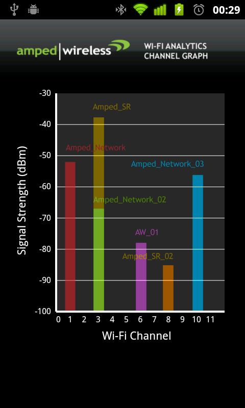
Could someone help me in Labview? I got a result as shown in Figure 1. However, I want the graph to resemble Figure 2 that we can define the range of frequencies for each channel in the y-axis and maintain the amplitude for the x axis.
How to change the chart?
Figure 1
Figure 2
I have the range of frequencies for each channel, which are:
Channel
Frequencies
Channel 1
2401-2423
Channel 2
2404-2428
Channel 3
2411-2433
Channel 4
2416-2438
Channel 5
2421-2443
Channel 6
2426-2448
Channel 7
2431-2453
Channel 8
2436-2458
Channel 9
2441-2463
Channel 10
2446-2468
Channel 11
2451-2473
Could only change the graphic on the front panel or have to change inside the block diagram?
Your answer is really appreciated.
Thanks & best regards.
Maybe you are looking for
-
Hello, those in about 3 days, I lose network connectivity on my laptop with Windows XP SP3. When I ping no matter what page of the console I get the following error message: show PING failed, error code 1450. I tried to use the option of repair in my
-
Original title: Olympus VN - 480PC Digital Voice Recorder Media Player I recently bought a new computer from DELL (Inspiron ONE 2320 with Windows 7) desktop and I connect my Olympus VN-480PC Digital Voice Recorder Media Player with the PC (to downloa
-
Why am I being asked to format my hard drives?
I have a problem, I asks me to format my drives that I've used, one is a USB that I have used before with the same stick of memory, the other is a memory card reader that I've also used before when transferring my photos, why this happened and how ca
-
How to remove windows 7 dual-boot keep windows 8?
I recently started my pc to double. Now, I want to keep Windows 8 only and delete windows 7. Please tell me the way without any harm to my pc or win8
-
error when starting application switching.
error when starting application switching.You are running version 120.15.12010000.3 adstrtal.shadstrtal.sh: the base connection could not be established. The database is out of service or applications provided credentials are wrong.USE: adstrtal.sh <