How to configure multi analog channels inputs in a single task
Hello I want to acquire two signals of the two channels (input 1 analog acceleration; analog input voltage 2) without using wizard DAQmx because I have to use standard vi I use usb NI 9234 any suggestion please I tried with a chanel and I got good result but when I try two delivery channels I errors please hep me
Hi Broutchoux,
What are the errors you get when you run your code? This is a mistake-50103? As long as your acceleration and your task of voltage use the same synchronization settings, you can combine the two channels in a single task. This should fix the error you receive. The article below has a picture that shows the configuration I describe:
With the help of different Types of Global DAQmx channels in the same task
http://digital.NI.com/public.nsf/allkb/3296BA2AEF586B7386256D6D00528E3D?OpenDocument
Tags: NI Hardware
Similar Questions
-
How to convert the analog voltage input form data to True and false (0 = fasle 0: 1-10 = true)
I want to use for LED or photo
10 V to ai0 reciece ex to see the LED or photo on front panel
Help me please
As part of the comparison, it should look like this.
Freelance LV cited above, you must provide additional information to get an apt solution
-
How to read / write several channels at a time target real PXI with a Board of 6259
On a PXI real-time target, I was able to access more of a channel at a time. The attached example illustrates the problem, when the second analog read occurs, I get a 'resource is reserved error '. It is my first challenge in real time and do not know how to proceed. In the end, I need to read three channels of analog input and analog output channel in the loop in real time. Thanks for any help.
Yes. You need to put the two analog inputs in a single task. There is only a single clock for reading of the analog inputs. If you use it for a task, this clock is reserved and the other task cannot use it.
That means connecting it to an analog output channel must do with it? If the ai0 is not connected to anything, why you try to read it?
The reason why you see something on this channel, it is that you see the residual value in reading the other analog input channel. When you have an open circuit, the amplifier may not load or unload by another value, if you see a ghost of the other channel. The entry for the land of analog unused thread and you'll see that the reading is zero or very close.
-
[fpga] Configuration of analog input or 7965R
Hi all
I have a card FPGA NI FlexRIO (SMU-7965R) with an adaptation module (NI 5733). I'm using Labview real-time 2012. My measurements are dominated with harmonic sound of 60 Hz, which is most likely due to the ground loop. I try to put my analog inputs (as opposed to the CSR, NRSE) differnetial mode to try to overcome the ground loop. I came across this link which explains how to configure the FPGA input channels-
http://digital.NI.com/public.nsf/allkb/08EF26D2E9041BC6862570E0001E442E
However, the installation program of the RIO device for my goal of opening, I found that there is no option to choose the channel configuration (as shown in the attached picture). This means that the analog channels are in differential mode by default? If this is not the case, how can I change?
Any help will be greatly appreciated.
Hello!
This KB is in what regards R, not FlexRIO product line series materials. I know it's a little confusing because the 7965 has an indicator of 'R' at the end of the model name, but the R simply it is a product with an FPGA that is programmable by the user.
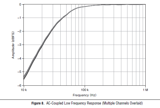
Unfortunately, the adaptation modules FlexRIO 573 x are all only ended then we will not be able to change to the differential. What is the frequency of the signal you're trying to measure? Another option would be to set the 5733 coupling AC mode, which would give the frequency response following, dramatically eliminating any sound below 10 kHz.
-
How to measure multiple analog input at the same time.
I tried to do a VI that controls a motor with two buttons. If I press the buttons, the VI took the analog signal from the buttons and the engine is running. Each button covers the different direction - to the left and to the right.
I need to enter the two report in the VI at the same time, but I can't. If I run the VI, VI takes only a random signal. I want to know what are the problems and how to solve them. Please help me.
You must use a single task for both channels. See if that helps.

-
How to write table values to analog channel?
Hi all
If I have a table of values, is it possible to write these values as an analog voltage and then stop writing when he arrives at the end of the table? If so, how does do this?
I have attached my code that generates a table of frequency swept sinusoidal voltages and I write that out to my analog channel, when I consult my output however, I get the same display of sinusoidal repetitive time and time again. I expect for example:
writing of wave of 1 Hz, 2 Hz, 3 Hz etc...
but I'm getting the 1 Hz wave over and over again, I selected samples in the sample clock and pretty much done a lot of trial and error and still no luck
 . Any help would be appreciated!
Daniel
Hi Daniel!
Take a look at this example (you can find examples of LabVIEW):
Gen CONT tension Wfm - Int Clk - no Regeneration.vi
Here is an another VI I did (see table). It is slightly different from the example of the LV and it should help you.
It could be that useful...
Julien
-
I use Labview 8.5. and the NI USB-6210 device.
I want to display the analog channels over the continuous acquisition.
I can use the table of waveform or waveform graph. Waveform allows you to eat a history buffer. This function is very interresting and useful for my system, but I can't change this value to programming (if I do not mistake!). So, I was wondering if I can also use the waveform graph, but I do not have how to make a circular buffer to replace function "history buffer. I have to use the waveform as a data type.
What is the best solution for my problem? I would like to know if my solution is good (graphic use of waveform) and if anyone has a solution to make an effective circular buffer with the waveform data type?
Thanks in advance, best regards, Daniel
There is an example that comes with LabVIEW called "XY table". It shows you how to create a history for a XY Chart buffer. The size of the history can be changed on the fly. You can adapt the VI "graphic buffer XY ' to work with a data type of waveform." This type of data consists of 3 elements: start on time, delta t and table of values. The only thing that you should be buffering is the array of values.
-
How to read the analog inputs of one Board of R for (PXI-7851R) series
You can guide me please with the steps for reading of the analog inputs of a series a. card I use as the target fpga PXI-7851R.
Have you looked at the examples provided with LabVIEW? There are examples showing how to read the analog inputs.
-
Storage of samples of several analog channels (life-long)
I use a USB6356 to read 5 analog channels (more digital input port A)) simultaneously until you press a stop button. The idea is to represent all the signals captured on a temporal scale after the acquisition.
I am convert and storage of the 2D array that is captured in each iteration of the loop in another 2D array in order to have an output of 5 table lines (one for each input signal).
However, Labview can not handle so much treatment in so short a time table (I think that the main bottleneck is the 2D Transpose VI table) and accidents very soon (I have to kill the entire process and restart Labview). Is there a better way to do this?
See you soon
Your problem is that you have horrible memory management here. Whenever you add in the table, more memory is allocated, then the table is copied. You are basically out of memory.
1. use samples of N, N channels, 1 table D of waveforms for your Read DAQmx
2. change your chart to a chart and move it to be inside the loop. Maintain chart, a story, so you can still see the X last samples on it (1024 by default).
3. save your data in a file. I recommend using the DAQmx configure connection before starting the task. This allows the stream directly to a TDMS file for further processing.
-
How to configure SCC-Ci20 ISP with SCC-68
I'm trying to measure a current analog signal using scc-ci20 scc-68 and pci-6221.
I used the scc-68 for analog measurement signal voltage using analog terminals, so the scc - 68 and pci-6221 are well configured.
What I did:
I added the scc-ci20 "measure and explore automated" under the scc - 68, CSC - mod 1
In the software labview in the DAQ assistant, I added a new channel for current measurement and physical channels appearing were "aio, ai1' which is the channel of the Terminal screw 1 Module and not of the scc-ci20 terminal block.
Also, I connect to the meaning of the Al to Al GND.
I don't know, if the DIF in how to configure the current module or how I connect the resistance to the Terminal Board and the scc-68 port.
Hi Egptos,
The SCC-CI20 channels are grouped in a differential measurement that is able to fill two separate loops, so the ai0 ai1 and. AI0 is the bundling of channels 1 and 2 on the module, who complete a circuit, and ai1 represents channels 3 and 4 that complement a second loop. The resistance of shunt used by the module to take the current measure is incorporated in the module.
-
How to display A / V (line) input in Windows Media Center
I am running Windows Media Center on Vista and have equipped with a Hauppauge TV card. It has analog (NTSC) TV input, digital TV (ATSC) and a composite video & audio. TV tuners work very well. How to choose the A / V input line to display? There is no "enter" of the remote control button. I know that the signals are there because I get a picture of the video and a slice of audio using Win - TV (really crappy software).
In the Windows Media Center Setup, it says:
Cable
Satellite
Antenna
Is it possible to have the A / V input see the place as a 'channel '?
Thank you;
Andy W.
Hi Andy W,.
You can't see the Audio/video entry up as a channel.
Reference:
http://support.Microsoft.com/kb/942375
http://Windows.Microsoft.com/en-us/Windows-Vista/TV-on-your-computer-understanding-TV-signals-and-TV-tuners
http://Windows.Microsoft.com/en-us/Windows-Vista/what-should-I-know-before-adding-TV-tuners-to-use-with-Windows-Media-CenterBindu S - Microsoft Support
[If this post can help resolve your problem, please click the button 'Mark as answer' or 'Useful' above]
This message. [Marking a post as answer, or relatively useful, you help others find the answer more quickly.] -
How to set up digital channels to change values on the trigger and the counter in c#
Hello world!
I work with the driver NI - DAQmx 6025 and want to know, how do I configure the digital channels in c# for control lines different ports by trigger rising "PFI0" and the meter "ctr0.
digitalWriteTask = new Task();
digitalWriteTask.DOChannels.CreateChannel ("Dev1/Port3 / line0:7", "", ChannelLineGrouping.OneChannelForAllLines);
digitalWriteTask.Control (TaskAction.Verify);digitalWriteTask.Triggers / / how to configure to change Digital line on rising "PFI0"?
digitalWriteTask.Timing / / how to configure to change Digital line on County "ctr0?
-------------------------------------------------------------------------------------------------------------------------------------------------------------------------------------------------------------------------------------------------------------------
Hi an alle!
Am mit dem OR-DAQmx 6025 und möchte like wissen, die ich wie digital channels in c# konfigurieren muss um einzelne Ports der Leitungen auf dem Trigger "PFI0" und dem Zahler "ctr0' anzusteuern.
digitalWriteTask = new Task();
digitalWriteTask.DOChannels.CreateChannel ("Dev1/Port3 / line0:7", "", ChannelLineGrouping.OneChannelForAllLines);
digitalWriteTask.Control (TaskAction.Verify);digitalWriteTask.Triggers / / Wie konfigurieren, um den logical Pegel eines feature pine bei der der zu winds PFI0 goods?
digitalWriteTask.Timing / / Wie konfigurieren, um den logical Pegel eines pines beim ctr0 zu go digital?
NEITHER told me, with the NOR-DAQmx 6025 driver not supported!
ICH habe von NOR learn, dass dies mit der 6025 OR AQmx supported wird nicht!
-
Exception on the creation of a second task with Analog channels?
I'm getting an exception '{error =-50103 = "is reserved for the resource specified. The operation could not be performed as specified.\n\nTask name: _unnamedTask<5>\n\nStatus Code:-50103 "} ' when I call Control(..Commit) on a task with Analog channels, I just created."
At the time of creation, I have another task set and running in the "we demand" move that uses another set of analogue channels in the same card to acquisition of data (NI6229).
Is there a limitation on the number of tasks that can use analog in the channels of a single card?
Thank you
Go Paul
Because the analog inputs share a unique clock, you can have only one task running. You can have as many channels as you want in a single analog input task, however.
-
How to read 4 similar channels at the same time with the MCC
Hello
with the mcc libraries and a card PCi-6034 classic (by calculation of the measure), I want to read 4 analog channels at the same time. I have a "scope" with 4 channels. How to read 4 channels at the same time with the mcc?
MF
Hello MF.
Thank you for using OR support. I guess you try to program in LabVIEW. Where exactly did you get the MCC library of?
-
How to measure differential analog signals
I read the hand signals and measure single-ended and differential, but I still don't know if a method is appropriate for my applications. Basically, I connect a BNC to one of the analog channels. The NLC has the real signal in a single thread (internal male) and land in the other thread (external shielding). I connect different components to different analog inputs so that they cannot share the same field (or the negative terminal). What is the best way to acquire this kind of data. It seems incremental settings on Panel (BNC-2090) different records between, say, ai1 and ai9. I don't want that because I want to record the difference between the two wires that are connected to the ai1.
Who said that a differential signal is connected to two different BNC? You need to look at the manual? The diagram in figure 2-2 is quite clear on the connections on the way in which the shield is connected in differential mode.
Maybe you are looking for
-
I followed the instructions in all the other threads, and nothing has worked. I tried safe mode and that doesn't work anymore, I went into the page permissions and all enabled for this page and still no luck.
-
Toshiba Canvio Alu unrecognized hdth305ek3aa
I used the usb drive mentioned above on Vista and Windows8.1 without problems. To save storage, I deleted some of the files it contains.Now that the drive is still recognized in Vista without problem.But when using Windows 8.1 the usb in the toolbar
-
BUSCO los drivers of hp pavilion 17-e187nr mi
Hola estoy buscando los drivers mid tower hp pavilion 17-e187nr are her busque in the pagina e even don't con mi number producto y encuentro el producto pero no los contains drivers cambie el windows than tenia muchos problemas por y restblesi pero a
-
When I go to start-run and type ipconfig it happens only for a second. How I keep reading?
When I go to start-run and type ipconfig it happens only for a second. How I keep reading?
-
Are there 3 partitions in iconia W510 win 8, primary, restoration and mbr partitions?
Are there 3 partitions in iconia W510 win 8, primary, restoration and mbr partitions? I'm freezeups and other defects. I tried recovery and saw what looked like 3 partitions. tried to format the C: drive then tried to reload the dvd.still system's gl