How to connect Labview to PLC Modicon Quantum (140 CPU 311 10) with Modbus
I was wondering if someone could give some tips on how to connect Labview to Modicon Quantum plc (the card is 140 CPU 10 311). I am eager to serve a Labview HMI to control the controller that is used to implement the control PID with a VFD. Currently I can communicate via Modbus to the API for programming using UnityPro XL, but I have no idea how to connect Labview. I read the article on place OR "connect Labview to any PLC via Modbus", but I don't know yet. Any help will be greatly appreciated.
Hey Greener.
Communicate with the PLC via Modbus usually requires the Datalogging and Supervisory Control (DSC) Module to have this feature available in LabVIEW. The white paper which indicated you using this module, which may explain why you can't get the communication at work. If this is something you don't have, and purchasing a license is not an option, then you might be able to use Modbus unofficial libraries to get the functionality you need. I have included a link below to a Modbus for LabVIEW library that you can try.
DSC module:
http://sine.NI.com/NIPs/CDs/view/p/lang/en/NID/209851
Modbus Library:
http://www.NI.com/example/29756/en/
Kind regards
Ryan
Tags: NI Hardware
Similar Questions
-
Hello
I try to connect LabVIEW to controller using an OPC server of NOR. Its a controller logix (Allen Bradley) L23E Compact and I find it difficult to obtain the device driver. Please help me with this topic and a link explaining how it would be useful to connect labVIEW to PLC.
Thanks in advance,
Sunil
Hi Sunil,
Regarding the driver: See the taken list supported device & driver plug-in for NOR-OPC Server
Regard to the connection in LabVIEW: You have two main options that depend on the question of whether or not you have the LabVIEW DSC Module. As seen here, you can either use variables shared with DSC to access your OPC tags, or you can simply use DataSocket VIs contact them directly as an OPC client. Some documents that may be useful by adding your specific hardware can be found here and here.
I hope this helps!
-Greg J
-
How to connect Labview to a USB sensor without existing driver?
Hello
I'm currently trying to a pressure transducer Omega PX409 USBH will display a reading in Labview. The transducer is USB connected, and the software that provides the Omega shows a reading and therefore indicates that the sensor is connected to the computer. However, it is not recognized by Labview or NI MAX. Although the pilot NI VISA Wizard recognizes the USB connection, it I cannot install the INF files that it generates on my computer. I'm pretty stuck on how to proceed in order to write a driver that displays the data in Labview. Any help would be appreciated!
malsko15 wrote:
Yes, I have updated the drivers FTDI and am able to contact my device via Hyperterminal. How can I integrate Labview into that?
Well, you have your hardware tested and working, half the battle is won.
Series communications are quite simple in LabVIEW using VISA.
Here is a small example of how to write and read from a serial device.
-
How to connect a Dell's VGA screen to my Mac Pro with cinema display 27 inches
I have a Mac Pro with a display of 27 "cinema, and I want to connect a VGA Dell monitor I have laying around. I want to have two monitors to my larger work. How can I do this? What should I do?
Hello esala23,
Thank you for using communities of Apple Support.
I see that you want to connect another screen on your Mac. You will love it, it's the best thing that I have to make my job easier and more efficient. Take a look at this article to get started with a second screen on your Mac Pro.
OS X El Capitan: connect multiple monitors to your Mac
You don't mention what model Mac Pro, but assuming that it is the most recent, this article can be useful:
Use multiple screens with your Mac Pro (end 2013)
Best regards.
-
How to connect a bar of its samsung bluetooth to a pc with a dongal brodcom?
It says its connected with the pc, but the Soundbar has not seen the pc to the pair, the devices to work how to fix this problem all drivers watched on many forms still does not help please thank you? Windows 7 a2dp could be the problem not sure
I had this exact problem before. Broadcom Bluetooth drivers are broken. They do not have Bluetooth controls as they are supposed to. So you end up with Microsoft's Bluetooth system, which does not audio services. A2DP appears not to be a protocol that allows Microsoft.
You need to replace the Broadcom dongle with a dongle that uses of Toshiba Bluetooth system.
-
Greetings,
Please can someone tell me how to connect LabView to LOGO! 0BA7, is there a LabView for PLC interface or some other toolkit?
Thank you.
For an automaton, you have the option of the DSC Toolkit or the modbus library - https://decibel.ni.com/content/docs/DOC-30140
-
How to connect labview to proteus in order to send commands to the microcontroller AVR, there a useful link or source code?
I've heard talk about VISA can you help me with a code example or source?I don't know anything specific to the APR, but Finder of LabVIEW example has many examples on the realization of serial communication ("Help-> Find examples.." then look for series). If you know the Protocol, then you can use the samples to create right necessary read and write commands.
Also a quick search on Google for 'Labview APR' had this as the top most successful:
-
Control PLC Modicon-Quantam of Modbus TCP/IP Ethernet.
Has anyone use LabVIEW to program a PLC Modicon-Quantam successfully using Ethernet TCP/IP? I tried the examples MB Ethernet (master/slave) in the download nimodbus121 and it doesn't work. I really need to know the best way to connect and communicate to a PLC Modicon-Quantam using LabVIEW, Ethernet Modbus TCP/IP using the Excel spreadsheet. I need to write entry registers (write) shift in and read from holding registers. The software that I SMTX Modbus/TCP Master control ActiveX does not completely for me. I can ping to the controller from cmd prompt. I saw this webcast - creating a server of e/s Modbus TCP with the LabVIEW Datalogging and supervisory Control Module 8. I've also seen a webcast on OLE for process control (OPC). What should I write LabVIEW control and view records by using LabVIEW flags? Someone at - it a LabVIEW example that I can start with? Should I buy the DSP module for $1280,00? This will solve my problems?
If you have found return data that you do not understand that I recommend trying to send output known of the automaton at least to determine what kind of conversion has to happen. This document talks about the Optomux protocol that can be used with programmable automata. You will need to find specific documents that tells you how to convert these data into LabVIEW. You can also start a new forum, since this is a separate issue from the original.
-Hunter
-
Connect LabVIEW to Schneider Electric M258 Logic Controller (TM258LF42DT4L) error - 1967353901
I was wondering if someone has never connected this particular PLC before LabVIEW. I'm trying to control instruments connected to this API. These instruments aren't NEITHER, therefore they that I could not directly connected to the device via USB, GPIB or VISA. Whenever I have try t connect following this tutorial OR (http://www.ni.com/tutorial/13911/en/), I have an error message to my shared variable.
The possible reasons: LabVIEW DSC: (Hex 0X8ABC8FD3) the I/O modbus server cannot connect to the Modbus Ethernet slave device. Make sure that the slave Modbus Ethernet device working properly and that the connection between the master devices and Modbus slave is configured correctly.
Any help on this approach or suggestion for others would be greatly appreciated.
NOTE: This controller communicates with the CPU I use via a RS485 / RS232 serial port.
SAM
Right, but if the unit will not pass a review of the communication of its native software so it is not really a chance that LabVIEW will be able to communicate with him. I could contact Schneider and see if they can help you make contact with their software, we can worry about communicate using LabVIEW.
-
How to connect a cluster of berries to a waveform graph
I'm trying to reproduce the pattern-block which is attached to this issue, but I don't know how I connect the waveform to my clusters of berries. I get an error that "the type of the source is table 1 d of cluster of 2 elements. The sink type is 1 d doubles [64-bit real (precision ~ 15 digits)].
You need a chart xy, not a waveform graph.
(Remember also that this table index is resizable. You only have a single instance. Your photo code is old, ~ LabVIEW 4.0 or MORE)
-
How to connect to an ip camera?
Hello people,
I develop a Train RC to monitor an accelerator of electrons, with an IP camera to stream video to the host PC (since it is a prototype, I bought a generic camera). I read a lot about how to acquire video of these cameras, and it seems to me that the best way to acquire these images is to use an active X control, but since this is the first time that I work with CompacRIO and Labview, I don't know how to open communication with the camera. I think I do as 'TCP connection open', but I cannot understand how to connect its use. I'm probably going to send two channels, one with the login, and the other with the password. Does anyone know how to do?
After that, how can I send the video to the activex control? Maybe I should use the block open Automation and nodes of property/Invoke, is - that correct?
I have the camera recorded on windows library, so I can see and select from Labview. By default, the camera uses port 80 to communicate with the PC.
If you would like more information to help, just tell me and I'll post.
Kind regards
Vitor
In fact, I already solved this problem. This camera is a fake Foscam, so I do not know the manufacturer (probably Chinese). Anyway, this ip cam has an .ocx library, and what I did was to call using activex and used an invoke node where I found a function of connection. Now I can acquire video from the camera using labview.
Thanks for your concern!
-
6009 USB + encoder Lika I41 - how to connect?
Hello world
I'm new to this forum and I'm new to Labview so. I started to learn a few weeks ago and I have to solve a few problems. I am not able to come up with my own, and that is why I ask. I went through very simple LabView courses and now I'm in more serious trouble.
I have first - the NI USB-6009 device and an incremental encoder Lika I41-h-500ZCU46L2. He has 8-cable and is described here: http://www.lika.pl/pliki_do_pobrania/QR%20I28_I40_I41.pdf . And now - I know the basics on the encoders so the description of cables is understandable to me. I don't know how to connect it to the USB-6009? I need to do a VI that will count the pulses and the output of the camera each X impulses. But I want to start by counting pulses.
Any help will be MUCH appreciated.
P.
Hi you can connect power 5V to encode. Connect to the encoder output to PFI0 encoder for the event USB6009 GND GND line do VI count on PFI0 and USB6009.
-
How to connect an International ST75 components fluid flow meter to the DAQ system?
Hello
I am trying wire a ST75 meter to my DAQ system consisting of a device PCI 6052E DAQ, SCXI 1102 b card and a block to connect SCXI-1300. 1102 b has four 249 Ohm resistors connected to channels 0-3 for use with the current of the flow meter signals.
The flow meter has two output signals 4-20 my and RTN, SINK, SOURCE and com connections The documentation is not clear how to connect the sensor to the Terminal Board, other than to say if the two output signals is used, one of the sons of RTN are used. So far, I can not get the signal from the flow meter to work in LabView, so I don't know if I have it plugged properly. Currently I have 1 wire OUTPUT on the Terminal Board + CH2, CH2 - wire to the chassis ground terminal and the COM lead on the sensor.
Thanks in advance.
Towards the end of the manual there are wiring diagrams:
SINK/SOURCE/COM are used for pulse ouptuts. It seems that there are two outputs, one for 4-20mA temperature the other for flow.
The one you need (flow) conjnction with RTN wired to use the + and - (or COM) your DAQ hardware.
-AK2DM
-
How to connect incremental encoder to NI9411?
Hello
I need to connect an incremental encoder to a NOR-9411 digital input on a chassis cRIO module to use for high-speed triggering. I'm having trouble to know how to connect the wires needed to the encoder until the 9411 correctly.The son of transport the following signals:
A red
B Green
Z Brown
+ V blue
OV-OrangeI'm fairly inexperienced with the connection of the sensors to LabVIEW gear, then please let me know if I can provide more information on my installation.
In addition, attached is the datasheet for the encoder.
Thank you very much!
Alex
Hi Byrd,
Thanks for the post and I hope that your well today.
I'm afraid I'm not totally sure what is your problem.
The NI 9411 manual can be found here: for additional reading.
The manual explains how to connect unbalanced devices on the 9411.
page 12:
"An example of asymmetrical device is an asymmetrical encoder. Connect each of the encoder signals (phase A, phase B, and)
the index) to one of the pins in a pair of pins of DI. Figure 5 shows the connections for an asymmetrical encoder. »In labVIEW, you can then create a DAQmx task to read all digital lines.
Hope this helps to get started you,
-
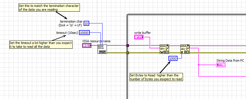
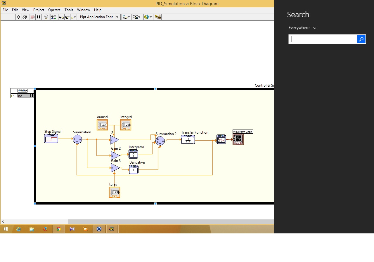
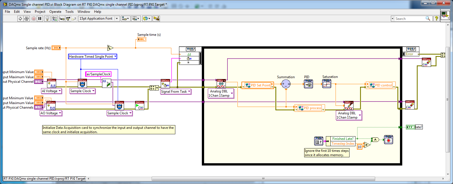
How to connect a simulation on the design of controllers to DAQ card?
Hi guys... I have problems about control and design on the way to the simulation I just do simulation PID and I can not to connect to the path of the simulation DAQ card in the control design (function)... can someone help me how to connect that?
Ayubi,
First of all, remember that the control and the Simulation has a PID in the Palette "control and Simulation > Controllers.
Then, to connect to a data acquisition card, you must use the DAQmx interface is there to connect. In general, National Instruments recommends allows you to deploy a controller a real-time system, but most likely your Windows computer should be good enough for your application. Please see the example of the expedition (in 2013):
C:\Program Files (x 86) \National Instruments\LabVIEW 2013\examples\Control and Simulation\Simulation\Real - time\DAQmx\RT PXI DAQmx single channel PID.lvproj
If you don't have a LabVIEW Real - Time (RT), you can simply open the VI:
C:\Program Files (x 86) \National Instruments\LabVIEW 2013\examples\Control and Simulation\Simulation\Real-time\DAQmx\DAQmx single channel PID.vi
Remove the shared Variables in the code and he would be executed on a computer with a DAQ card.
Maybe you are looking for
-
How to lock my iPhone 6's screen so it does not move between portrait and landscape?
How to lock my iPhone 6's screen so it does not move between portrait and landscape?
-
Satellite M30X - power management problems does not
Hello I am new to the forum and some difficulties with my power management settings.Don't know why, but don't can't Hibernate my system or to keep. If I go to the Start button and try to shut down the system, I can only close or restart the computer.
-
Pavilion hp2-1124: no power on the desktop
Came home after the weekend and there is no power. No light, fan, nothing. There was no indication of power problems before we left (strange noises, loud fan, flashing). The cord is similar to a cord high tower (external power supply) and I ordered a
-
Audio is disabled... All the suggestions/help?
Hello. whenever I convert an episode of a show like family guy, the simpsons and american dad, the audio is always disabled as you hear people before you see their mouths move. Someone else has the same problem or any suggestions on how to do to stop
-
Sometimes when I type the letters do not appear immediately
Lately when I type the letters don't appear on the screen. I spent the last hours of the couple trying to clean up my computer, but I don't really know what could be the cause. This happens in all programs.