How to generate a square wave of continuous digital output using USB 6343?
I need to generate a square of 600 kHz from my 6343 wave. The specifications indicate I could use PINS P2.0, but I get an error saying that it is not supported.
Thanks in advance for your help.
Jodi
Dan,
Thank you very much. Counter method worked very well.
Jodi
Tags: NI Software
Similar Questions
-
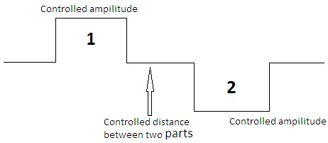
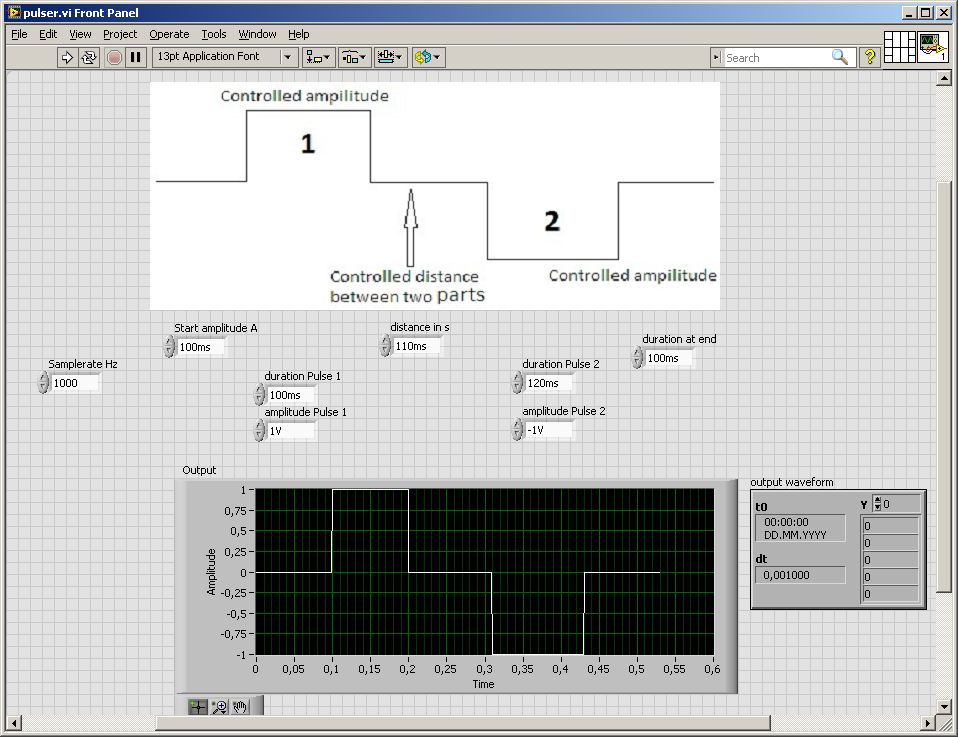
How can I design square wave which has a positive and negative values equal to the other and separated from each other by controlled time or distance, as indicated in the figure below. and enter this signal in a data acquisition.
At the time wherever you go for the beautiful diadram, you could have done the vi

Your DAQ would like a waveform (table of values and dt ak 1/sampling rate)
If you set the sampling rate you know the length of the array, create a matrix of zeros and set the values of the two amplitudes...
Because I don't want to connect other duties
here are some photosAnd it
does have a few drawbacksleaves to be desired in my solution, just think... rounding errors and what might happen if the tables are becoming more... -
Square wave generation phase offset problems using PXI6602
Hello
I'm generating 2 signals using an incremental encoder AB using a PXI6602 to simunlating.
Signals must be offset square wave, 34,133 Khz, by 90 degrees, which I'll put dividing (1/frequency) into 4 and put the result in the knot of late initial .vi DAQmx create channel (frequency impulse Co generation).
Resulting signals phase difference however does not consistantly measures 90 degrees. 1 in 5 rounds of the vi has at least a matter of resulting in a test phase angle has failed.
Can someone suggest a stable solution for this.
Thank you
David
John_P1,
After posting the previous comment, I went back to play some more with him, and he now runs and returns a positive result every time.
The change that has had the desired effect was for the type of trigger that I had selected (Advance Digital Edge). Change this to start digital dashboard whose value fall of dash, the error disappeared.
Feel free to always criticize the vi and suggest / modify to improve stability / efficiency.
All feedback is voluntarily accepted

Thank you
David.
-
How to generate a sine wave of table of values?
I have an array of points (values) around 1000. I want to draw them in different types of waveforms - triangle, sine, cosine, etc..
How ca I do that? For the waveform of triangle, I was able to split my table into 2 halves equal and draw the first half and the separately half second to generate a waveform of the triangle. But how to sine, cosine, Sawtooth etc.? It is a matter of urgency. Prompt response will be appreciated. Thank you
Hello
The VI in math palette is a polymorphic, it accepts the input also array.
attached a VI for your reference.
VI generates 1000 randon numbers and trace the sine and cosine wave.
-
How can you measure a wave of the ECG Simulator using a 6036e?
I have an ECG Simulator I'd like to test. How I would setup a dac 6036E, scb - 68 card to test waveforms? Is there a screw that could help with this problem. Thank you.
You're in luck. NOR has a free biomedical Toolbox that should take you far: http://zone.ni.com/devzone/cda/tut/p/id/9037
There is also a biomedical forum: http://decibel.ni.com/content/groups/biomedical-user-group
-
How to generate a public and private key when you use reCAPTCHA anti spam protection forms?
Hello
I designed my first website using muse for a customer. now, I want to insert a protection against spam reCAPTCHA. I followed the guide step by step from adobe, but when I want to log in to the google administration console, I'm stuck. can I use my login information to design companies that I have a business google account? and if so, where can I find the app because it does not appear on the console connection that I currently use.
Help, please!
Hello
Please click the link below and login with google/Gmail code. you or your organization
reCAPTCHA: easy on humans, hard on the Bots
If you do not have a gmail id then just sign up on google.com or gmail.com.
Concerning
Vivek
-
Hello
I want to generate the continuous signal and at the same time I want to read that signal that I generate using a single card DAQ. I want to generate signal and the received signal is synchronized and in phase.
I looked at several samples on the sync, but it quiet confusing. One using the same clock of entry while the other use a trigger to start. I use the PCI-6024E DAQ card.
Can someone help me in this regard?
In two of these screenshots, the task to HAVE started first (that's what you want, because it is the task of the slave).
Typically for AO, you can simply write a unique period of your waveform, and then regenerate again and again. Your waveform would be preset before the task starts. If you need to update the waveform on the fly according to enter programming during execution of the task, you would disable the regeneration. In addition, if the wave form is such that it cannot be easily represented by a predefined buffer (for example, it is a strange frequency which is not a same ditch at the bottom of the sample clock), then non-regeneration is the way to go.
Best regards
-
How can I get a continuous square wave to the duty cycle of 50% on one of the analog lines?
Hello, I had recently just buy an analog card to our system, and I'm still very new to labview. I have the PXI-6723, and I need to produce a wave square of 0 to 5 volts continuously. I used the square wave generator and used a writing funtion to one of the ports. This produces a momentary wave and that's it. I tried to put some time a loop around the square and watched as wave function. It produces constantly plots, but the write function always has the same thing. If I am the writing inside the loop function I get errors. Any help would be greatly appreciated. Thank you, Fred
Another function to generate the square wave, to change the generation of waveform buffer (the Subvi used) and to connect a control at the entrance to offset from the base generator functions. or simply use the add function on the output waveform.
-
FPGA square wave generator diverts loop calendar
Description of the problem:
I have a simple while loop with a structure of matter inside. In one case, I have the
Generator FPGA Sinewave sending the data of output to AO0, otherwise, I have
the square wave FPGA sending output to AO0 generator. The sine and square
waves are set to run at 10 kHzI also have a shift register that changes the State of DIO0 each loop through.
In this way, I can look DIO0 on my scope and say how fast the loop runs.When I choose the sine wave generator, the output on AO0 is what I expect. That
is I have a sinusoidal signal at 10 kHz and the loop speed is approximately 1 US. Everything is good.Then I move to the square wave. I get a signal square 10 kHz, which is good. But
My loop speed was slowed down to 50 US (it follows the square wave
exactly) is: once the loop defines the FS square wave and the
the next time through the loop, it defines the square wave to-FS.My problem is that when I generate a square wave, I expect the speed of loop
to stay fast he does it for the sine wave. You can see what my loop speed
slows to 50 (a square wave of 10 kHz) and then all my calculations that must
go in parallel with the square wave will also be slowed.Please help me with my understanding of the use of the square wave FPGA sub - VI
Thank you
RichSoftware of NEITHER: LabVIEW FPGA Module version 2013 SP1
OR hardware: USB-7855R R Series deviceIf you dig into the express VI, it will loop an SSTL until there is a change in value. The sine wave has no need to do so because the value changes constantly.
If you can, I recommend doing your loop a SSTL and configure the express screw accordingly. This will work as long as the rest of your code in the loop can be run in a single clock cycle.
-
How to generate a continuous ttl signal with a USB-6501
Hello everyone,
I am a beginner with LabView, so maybe my problem, it's very easy to fix.
I need to generate a digital output using a USB-6501. This TTL signal will then switch to a device. Basically, I need the digital output to be permanently to TTL high level until a user active departure is given. Then the digital output must stay to the TTL low level until another stop active user is given.
Does anyone have any suggestions on how to do? I have failed so far to get something different high TTL to my USB 6501.
Thank you very much.
Hi there, take a look at the VI I enclose. You can find more information about the device in textbooks and on this forum. I hope this helps
-
How to generate two different analog signals in two different screws
I use a card PCIe-6321 and a block of connection SCB-68. As it has two analog outputs, I use one of these outputs in a Vi to generate a square wave, and the other in an another VI to generate a sinusoidal output waveform. Each VI perfectly work separately, but if I run one then the other, the other sends no signal. Because I don't want to merge the two screws (it is more convenient to use them separately), how can I find out so that they work together (sometimes).
Of course, independent maps with timing motors, controlled by the works of independent screws.
Christian
-
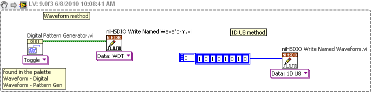
How to generate signals using NI - HSDIO.
Hello
I need to create two signals different pulse square. I don't know how to set their frequencies, number of cycles and FRP using NOR-HSDIO.
Thank you!!
You must create a set of data to send to the HSDIO. It only builds what you send to it. Suppose you want to produce a square on one channel wave. Implement the HSDIO for right channel, trigger, timing, etc. Look at the function HSDIO write nominated Waveform. It says name of waveform, but you can use the polymorphic selector (the area under the function) to select other types of data outside of the waveform, i.e. a table 1 d of numeric (U32, U16, etc.). You must create an arry of data that would be akin to a square wave. Or you could use the input waveform and create a square wave.
The simplest is the waveform because Labview waveform generator functions available. See the image below. If you want to use table 1 d, construct you a table or alternation of 1 and 0 to produce a square wave. The image below is only a partial code. Need to add the rest of the installation HSDIO functions.
-
NEITHER USB 6343 negative DC voltage after power function generator
Hey all,.
I'm having a problem with my DAQ. I'll generate a square wave in Labview with a generator function and that the output to my DAQ. The function exited through the acquisition of data very well; However, when the production is stopped, a negative voltage remains equal to the amplitude ("drawing" below). This happens if I use the express VI DAQAssistant, or manually create the channel, generate the function and the function read/write on the channel. This tension continues even after the VI is finished running. The only way to get rid of it is physically cut the DAQ and turn it back on. Any thoughts on why this might be, or how to fix?
Start VI
____|____|____|____|____|____|
____|____|____|____|____|____| _ _ _ _ _ _ _ _ 0V
____|____|____|____|____|____|____________ - A V
____|____|____|____|____|____|
End VI
Tom
I thought about it. I had to add some more to the clock. I had added a data point in the table of waveform which was written for the acquisition of data because the timer wrote n samples, instead of n + 1

So, to recap: I pulled the table leave the waveform data, inserted a '0' at the end of the wave, reintroduced the data of Y in the form of wave and incremented to the timer of a sample (because I added a sample for waveform data).
-
Continuous signal creation (using the PFI channels?)
Hello
I am new to the use of OR and its interfaces. I use the USB-6221, with its C API.
I need to create multiple channels of continuous digital output with the cycle of the frequency and the duty.
I used DAQmxCreateCOPulseChanFreq for the crt0 and crt1 channels and it works fine, but I need a few lines.
Can I use the channels of the PFI (PFI0-4 for example) for this purpose?
With the help of the DAQmxCreateDOChan I can set the PFI desired channels as DO, but how can I create the signal desired on these channels?
Best regards
Danny.
Howdy Danny!
If you try to build a train of digital pulses with a frequency cycle and specified duty then using counters shipped from the USB-6221 is certainly the way to go. Unfortunately, as you have discovered there are only two meters of material available on the USB-6221 (Ctr0 and Ctr1).
Fortunately, you can also use the digital output lines to efficiently create a train of pulses with a frequency cycle and specified duty. You will need create a table of examples which, when released at the specified sampling rate, looks like a period of your waveform. For example, if my sampling rate is 1 MHz and I want to create a square wave of 100 kHz and a cycle of operation of 20% low high/80% I would generate the following examples:
{1, 1, 0, 0, 0, 0, 0, 0, 0, 0, 0, 0}
Please let me know if this description is clear or if there is anything I need to explain more in detail.
Kind regards
-
Generate a continuous output of square wave with E Series DAQ cards
Hello
I use a card DAQ-AT-MIO-16XE-50 and labview 6.1 to generate the frequency divider. The first thing I want to do is to enter a continuous digital signal into the program so I can divide it. The attachment is the program I use. It's pretty simple, just read the output signal and put them all in a while loop to get a continuous pulse. But when I want to observe the waveform on the oscilloscope, I got some square waves unregular.
I'm a freshmen in labview. It will be appreciated for all her help!
Hello
If you are just getting started with digital i/o with traditional DAQ, I'd take a peek at some examples to see how to structure your code for both input and output. There is one here (http://zone.ni.com/devzone/cda/epd/p/id/1113) which should give some features similar to what you are looking for, but if you want more examples, you can navigate to the examples as a result of the article here (http://digital.ni.com/public.nsf/allkb/46D0C7360A10D25F862571B5007B4411), as long as you have installed them with traditional DAQ.
Maybe you are looking for
-
Hello I'm having trouble with this very simple table (which follows). I want to store data across a while loop that's why I tried with a very simple example. And it does not work. The data are erased each time through and I have to define the dimensi
-
Issues of the trial of Lightroom
I downloaded a demo for Lightroom CC.1. I loaded two cards to images. If they are recorded in the LR catalog?, where are the masters? I right click to "Show Package Contents" and without masters appear. Not good.2. I treat a picture in LR/save fas
-
correction and detail in lr5 tab
I don't have the lens correction tab or Details tab on the right side to develop the module. It is also apparent from the standard presets that were there disappeared. Any suggestions?
-
Where can I find the driver for GeForce 8600 M GT?
I had to download a new driver for my graphics (GeForce 8600 M GT), so I went to Nvidias homepage. When I found the right place he just told me that they do not have this driver and I had to find on the home page of dell instead. I tried to find it h
-
Managed review secure Channel before taking the course... can I still get emerit?
HelloI recently took and passed the VCP 310 FRONT to register for the certified course exam. I got an ID VCP Pearson VIEW when I joined the review and now I would like to take the class needed to become fully certified. So my questions are the foll