How to generate analog signals?
Hi all
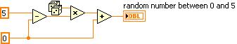
I'm trying to generate analog signals to simulate the position of the valve. I also want to simulate the position of the valve 0 - 5V (analog signal). I've implemented the numeric position of the valve by using the toggle switches, but I want to implement analog signals.
You can help.
Thank you
You can just use a random number generator.
Since you have no generator hardware signals of NOR, I'm not sure why you are posting to this Board. Generic questions of LabVIEW. Post to this Board.
Tags: NI Products
Similar Questions
-
How to generate a signal of persistent arousal in LabVIEW
Please can someone please help on how I can develop a persistent exciting in LabVIEW for identification, resembling her attached attached document (filtered white Gaussian noise).
Hello
Do you mean something like this:
And the code for this:
I hope this helps!
-
How can I use my PXI-6115 meter analog signal trigger to generate pulses of frequency
I work on a PXI-6115 DAQ card and want to using the analog signal to trigger the counter it's generating frequency pulses. The manual says the analog trigger is supported, but I can't use an analog signal to trigger the start of work, in the test, I use the counter 0 to generate pulses and use the signal input port analog trigger PFI 0, can someone tell me what it is? My test VI. & error message appears in the attachment.
Best regards
If you read the error you can see digital triggers are the available trigger only when you use the output of the counter.
You can work around this by setting up a dummy analog input task which will trigger an internal digital triggering when he sees the right analog trigger.
See this thread for more details:
-
How to determine the number of highlight ' to write ' for DAQmx generate analog output?
On the configuration of the stage for DAQmx generate analog output, there is a field "value to write. I can't find any explanation for what it is, how it determines the value to enter, nor what he writes. I am trying to go through the tutorials and it cling.
Someone would give an explanation?
Hello
To write value specifies the value to write in the channels, lines or ports selected in string parameters. In other words, this value will be the value of your DC output (for example if you enter 5, your output will be 5V). To get information on different fields in SignalExpress, access help"context-sensitive help. A pane will appear in your work environment that displays the coordinates of the field when you place your pointer over them.
For new users of SignalExpress:
Generation of DC signals with NI DAQmx devices: step in the DAQmx build, select 1 sample (on request) in the generation Mode dropdown. You can select a programmatic input to generate, or you can remove the check mark from the check box use programmatic input and specify a value for generating in the field of value to write . NOR-DAQmx help also provides additional information about the data generation.
Best regards
M Ali
Technical sales engineer
National Instruments
-
How to create an analog signal of a text or a binary file?
I'm trying out an analog signal of a file on a map of NOR-DAQ 6251 with labview 8.5. I found examples on the construction of a waveform, but I'm stuck at how read a text file and do a 1 d table to enter my amplitudes in the buildwaveform.vi and I can't find all the information on how to do it. Help or direction is appreciated.
Thank you
David
What if all you want in the file corresponds to the values of Y, then a text file with a value on each line can be read. Read from a usable spreadsheet file. It will return a 2D you can then use array index to get a column or if you select Transpose, the array returned by 1 d would be used.
If you want to create an example, use a 1-d array constant in a VI and pass it to the writing on a spreadsheet file.
-
How to convert an analog signal into digital signal
Hello
How to convert an analog signal into digital signal, such that each sample of the analogue signal corresponding to 1.2V will be represented as '1' digital signal and other samples of the analog signal (which are not 1.2V) will be represented (converted) ' 0' in the digital signal.
And how to view the wavefroms or graphical indicators signals.
Thank you.
If you have 1000 samples and you want to convert to digital, you get 1000 digital values. Attached, that's what I mean.
-
How to use generate multiple signals on a single DAQ Assistant
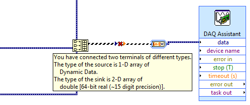
I am trying to generate several AO on my DAQ card, but I kept getting an error. I looked at the error and he said that I had to use a single DAQ Assistant. So, I created one, but I can't understand how to connect the signals. I get lines that don't connect. Is attached a picture of the installation. Thank you!!!
If you want to use the type of dynamic data, you must use the appropriate function. Do not use the construction. Use the Signal to merge. Then wire you the output of said directly to the Assistant.
-
How to get analog tacho signal in card PCI-6250 OR
Dear all,
IAM using Labview 8.6.1 and map NI PCI-6250. In my application, I need to get the power spectrum of the order for a given speed and signal of the accelerometer. So iam using labview example program command power spectrum(Analog_Tacho).VI. In my PCI6250 card, I have configured AI0 as the accelerometer signal and AI 1 as speed for tacho signal analog signal. In this sample program I can get the signal Amplitude of had it, but I can't able to get the speed profile. For iam speed using the encoder, encode this pulse digital I connected to the analog channel 1. If this connection is correct? Instead of giving digital impulses directly I tried the analog signal 0 - 10v for 0-based-1500 rpm. This configuration also does not work. Encoder PPR is 1000. Can someone help me solve my problem.
Kind regards
Vijay.
At 1800 rpm spin you at 30 Hz. for your encoder impulses come to 30 000 Hz. You must try the channel analog encoder to 100,000 samples per second or more. The chart of your analog inputs on a graph of time waveform to see if you get a clean signal.
With tacho analog vi, you will need to provide the number of pulses per turn, so it can determine the correct speed.
-
How to display any signals in SignalExpress read mode?
Problem: Read showing only 1 block of samples instead of ALL the samples taken when I click 'run '.
Installation program:
Monitor / Record:
DAQmx acquire analog input (Acq Mode: continuous, 1 k samples @ 10 kHz).
Create an analogue Signal (Signal DC 100kS/s, 1000 sample block size),
DAQmx generate analog output (N samples).
Reading: Same steps as monitor / record, except DAQmx generate analog output is continuous samples 1 k samples at 10 kHz.
I dragged my data in the folder of papers according to the Instructions of Documentation Help '5. Read the data.
All data is correctly written to a PDM file and converted to ASCII. How to see the length of reading?
Use: LabVIEW SignalExpress v2.5.1 Lite, NI USB-6221
It is a very requested feature that you can't do in SignalExpress - yet. One solution is to view the log monitoring/recording mode. It is not ideal, because you can only browse the signal not to analyze. Our apologies...
-
Hi all
I'm still new to LabVIEW, but I played a little enough to create a simple analog signal generator. Product signals appear staircased when displayed on an oscilloscope, but are smooth, when I read the signals in an entry (as shown by the graph on the waveform) analog. How can I change my program settings so that I can see this staircased signal?
I run LabVIEW 2010 and use a data USB X Series multifunction acquisition.
Thank you
-Olivier
-
How to pass a signal between 2 worksheets
I created a signal evaluation sheet and I want to transmit the signal that is to assess a separate spreadsheet that generates the signal. If I use the module generator frequency to generate the signal output so how a calculation sheet and read it as an input in the other worksheet?
Bill,
You can run only one sheet at a time.
How to transfer data from one sheet to the other would be to save the data in a file. DDF is the most flexible for writing and for DASYLab replay DASYLab.
Use of the files, data group of writing and reading data. The file must already exist to configure the module for reading data.
-
How to display the signal on a waveform graph in Labview Signal Express?
Hello
I want to display a signal in Signal Express 3.0 in a "waveform table", but don't know how to do it and I think that it may be impossible?
In Labview, there are two ways to view data, a 'waveform table' or a 'waveform graph. The great thing with 'picture of waveform' is that it allows you to set a length of history and you can see the data move to the left (option graphic strip) that samples are recovered. It works perfectly.
In Signal Express I can only select "Graph XY" or "Waveform curve" by doing a right-click of the mouse, but I can't select "table of waveform. Is it really true that it is not possible to view data in a graph of waveform "with Labview? (1 analog signal during streaming, 100 samples to read at the rate of 1 K)
Thank you in advance,
Enrique
Hi Enrique.
You are right that there is currently no graphic waveform in SignalExpress. The thing nearest you can join, is saved data under a log and then he looks one when recording (which I know this isn't quite the same interactive behavior).
For your last comment, you wrote 'waveform curve', but I guess you meant 'picture' here as well.
Sorry about that. We recently received this request, then perhaps in a future version.
Phil
-
How to generate an impulse to test short circuit in an inducer
Hello
IM new to labview and am in need of complete SURG - SURGE STRESS TEST
This test is intended to detect a short tour inter by applying a number of high
voltage pulses (or surge) for the selected winding.
Each pulse should produce one sinusoidal transient that eventually decreases to zero.How to generate the impulse using labview.
Hi Jessica,.
Please see the "pulse pattern.vi" function--> pallets of signal processing signal generation.
Otherwise, you can browse through examples of LabVIEW.
Kind regards
Srikrishna.J
-
Generating the signal as shown in the picture in labview
Hello
I'm using labview in 2011 and want to generate the second signal as shown in the picture attached in labview as I want to use it as input to implement adaptive filtering, if the first signal in the image represents the output of the adaptive filtering area.
May I know how to generate a second signal.
Thank you.
-
Connection diagram missing in DAQ Assistant generate the signalling block
This is my first post so please excuse the quality of my description.
When I double click on the block of data acquisition - Assistant, there is no tab connection diagram I can access to see how things are wired to the top. I have a NI USB-6211 connected by USB and it is used to control many different sensors and a power supply. Currently, he works for everything and is hard wired correctly, but only blocks DAQ Assistant has a connection diagram available, the other are not. One who has a connection diagram is used to measure a voltage. Others who do not are used to generate a signal. I would really like to be able to see patterns of connection for each block.
-Any help would be appreciated
-Thank you
You can always do like those who never use the DAQ Assistant and read the manual. Right click on the device in MAX and selecting "stitching of the device" works too.
Maybe you are looking for
-
My iPhone 6 won't accept that the first digit of my password. I tried to force restart and no help?
iPhone 6, I can only enter a number for the password. Tried to force the reboot and no help. Cannot access my phone. I can send text on the phone and calling on the phone. ???
-
How can I activate the lockscreen so that it blocks whenever I close my laptop? Mine is on the lockscreen when I turn it on, but if I close it, it will not be on the lockscreen when I open it again. The music continues to play even when I close my la
-
is there a free software online to save videio to make a videio to share on the web? Thank you
Hello, is there any software available, for free, online to download so that I can do videios. What are these screenrecorders I see, and they work with windows movie maker >. Thank you very much
-
Pavilion Dv4000: Help the disabled system password Bios
Hi guys,. My old friends laptop has a password on the bios and he can't remember the password. can someone help with this at all? HP Pavilion DV4000 DV4046EA Disabled system [03637] Thanks in advance
-
List different with JSON types
I created a flat list using the group view: no technique mentioned here: http://supportforums.BlackBerry.com/T5/Cascades-development/ListView-no-header/TD-p/1737097/HIGHLIGH... I'm changing my list to display differently depending on the type, as ind