How to trigger an analog input to analog output
Hello
We have two signals, one of which is a glow that we generate via a PCIe-6361 and a BNC-2110 to my experimental system, and another who is directly related (like an echo) I want to acquire every time that send us one.
What I tried:
-Generating a signal pulse and the bond of an output channel for the PFI0 one.
-Using the pulse generator virtual daqmx (pulse CO-tiques).
I'm sure there is an easier way to do it, but I can't find it, could you help me?
Additional info: attached the two signals (blue, yellow emissions receive), I want to talk.
Thanks in advance!
Assuming you are using the same card for AO and AI, you should be able to use a trigger to start the task of AI with pulse to start the task of the AO.

Tags: NI Hardware
Similar Questions
-
Trigger start analogue does not work for the tasks of the analog output
Hello. I wonder - what someone has tested the trigger mode analog start for continuous output voltage-. example of VI under hardware input and output - analog output folder in the Labview.
My camera's SMU-6358, who has two lines APFI and supports analog trigger. Although it is very difficult to find information on the use of analog trigger for analog output of the tasks, what I've learned so far is to connect the interested analog trigger signal (such as an external noise) on both the AI channel which is used as a source of relaxation (ai0 in my case) and a two-channel (APFI0 in my case) APFI.
During the test the example above vi, any level of relaxation that I put (even with 0), the task of output did not work at all. No error message is returned either. Just for your information, I do physical tests, not only the software simulation, so no signal means no signal.
Any help is appreciated!
I have here is that the solutions to this issue, just want to say thank you to all who have helped me on this subject.
Use the analog analog trigger output tasks, make sure that the trigger signal (input HERE) is connected to APFI0. There is no need to connect the trigger even signal to ai0 if you do not want to save the trigger signal. However, if you do not want to save the trigger signal, connect the trigger signal to both ai0 and APFI0 with a signal splitter. In the latter case, the task of the AI shouldn't take the same trigger that the task of the ao. This means that you can start your registration with or without a trigger, while leaving the task of ao wait a trigger of some signal. This is useful in a situation that you only want to generate ao task to a certain trigger event, as when a signal reaches a certain level of sound pressure.
-
I am newbie in Labview... and it is very difficult to find good help and tutorials... it's really disappointing.
I want to find a good simple example of 'the analog output control "...
I found these 'words' somewhere on the internet in the file 'DAQBasic.pdf '.
It is mentioned I need 'VI' easy, but I can't find something like 'Easy VI' in the functions available.
There is far too much info anywhere and there is no structure...
How can I 'the analog output control "?
And please, I want simple examples...
Thank you!
Why spoil things by connecting the key to something?

Your code should be close to what you asked. You want to make sure that there is no case of timeout. I would use the event to change value instead of the key down. At startup, the acquisition of data code run once and then after that, wait key. A couple of different ways to fix this. Simply place the code for the acquisition of data inside the event.
-
How to trigger and outputs analog and digital Outout tasks begins on a counter to start?
Hello
I'm trying to synchronize the start of a task outputs analog, a task of digital output and a task of counter. I want to start the counter to serve the master trigger and analog and digital tasks to synchronize his departure.
I guess I need something like:
analogOutputTask.Triggers.StartTrigger.ConfigureDigitalEdgeTrigger ("?", DigitalEdgeStartTriggerEdge.Rising);
digitalOutputTask.Triggers.StartTrigger.ConfigureDigitalEdgeTrigger ("?", DigitalEdgeStartTriggerEdge.Rising);
analogOutputTask.Start (); Slave 1
digitalOutputTask.Start (); slave 2
() counterTask.Start; n / / master
Where? is a string specifying a command source for the beginning of the task of the meter. However, I can't find what this string. Any suggestions?
Thank you!
-Jon
Just FYI, the solution to this problem as well as some other ones is encapsulated in a short example .NET, I created. It is on the Web site of EITHER:
http://decibel.NI.com/content/docs/doc-15500
This project shows how to synchronize all your analogue/digital outputs through tasks and forums in terms of synchronizing Calendar and start clock.
-Jon
-
How to read the analog inputs of one Board of R for (PXI-7851R) series
You can guide me please with the steps for reading of the analog inputs of a series a. card I use as the target fpga PXI-7851R.
Have you looked at the examples provided with LabVIEW? There are examples showing how to read the analog inputs.
-
How to write constantly to analog output and read from analog inputs
Hi all -
I had a question about writing continuously to analog output reading simultaneously an analog input.
It's my first time to post a message to the community, so please let me know if I made mistakes.
I use Labview 2011 with a NEITHER-DAQ USB 6215.
I'm looking to generate a waveform and write it continuously in an analog output. It is then connected to an entry on the acquisition of data, where I am trying to sample the analog signal. (I realize, there is a system of trivial, but I'm hoping to build on it once I have run).
The task of reading from the analog input works fine, as I tested it in several other cases. I have a problem writing to the analog output.
For this task, I tried to follow the "Gen Cont Wfm Clck Int' VI to generate the wave form and start the task. I then try to write to the output of the analog timed loop. However, it does not seem to transmit a signal and doesn't give me any errors.
I have attached the VI but also a screenshot.
Please let me know if anyone has any ideas. I would really appreciate the help!
Thank you
Peter Borgstrom
We will review your tasks one at a time. First of all, the task of generation/Analog output Waveform. Generate you a waveform (I'm unsure of your VI if it is a fixed waveform or not) and send it to a defined output function to produce a waveform continuously, using N-channel and samples of N (where you set not these previously). You should not put this inside has timed loop, as the DAQ hardware has its own clock - if you simply put it in a while loop (with a stop to break out of the loop), the loop will call the function for the first points of N, wait until all N have been taken out, then call it again to another N points (up to what you press Stop).
Now, suppose that you have the output connected to a load voltage (say a decent resistance). You can wire the input terminals of your A/D converter through the same load and set up a similar analog input loop, running in parallel (i.e. in its own independent of the OD loop, while loop). You pourriez start together (with, say, a merged error since the initialization code line loops HAVE and AO become lines of error in "loops of sampling" described above), but you might want to delay loop (a little) the AI so that the OD has a chance to set the voltage before the bed.
I hope this helps.
BS
-
How can I pause and resume the analog output using DAQmx?
I use a DAQ hardware to produce an analog waveform. I would like simply to break the output of the wave and then resume where it left off. I use DAQmx and LabVIEW 2011.
I've seen examples that use a digital or analog break trigger, but I would take a break in the software only. How can I do this?
-Joe
Hi Joe!
I spent some time thinking about it and I realized that you can technically use a fundamental mission of the analog output, as you previously wrote that runs continuously. However, the generated output samples are controlled by the sample clock pulses, and can be manipulated to fit our needs "suspension."
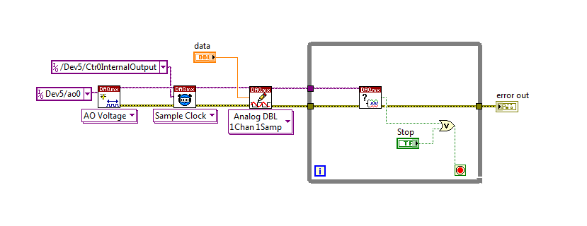
To do this, we will need another counter task that generates a pulse train (see our examples of shipping under material input and output > DAQmx > generating digital pulses > generate dig Pulse Train - Continuous.vi) that stops and starts the user to choose. This can be in another quite VI or controlled by software. We will use this as the task of our output sample clock.
Then, the task of the AO, wire a constant to the sample clock source and select ' DevX/CtrXInternalOutput"based on the counter that you specified in the task of counter. You will need to choose "I/o name of filtration" and check the box that says "include advanced terminals' and right-click of the constant. See picture attached as a reference. In this way, the task of the AO is constantly running, but it generates only actually all data when the meter running task.
Let me know if you have any questions!
Have a great day!
-
How to send a pulse only to analog output
I send a function rect through to the ao, thorugh the transmitter transducer, then a receiving transducer through AI. Although I'm kind of a signal, I can see that there is something wrong. What I think is happening, is that the pulse is transmitted continuously while I want it to be sent once. of the received signal, waiting for the signal to reach 0.2/1500 s as the medium is 0.2 m in diameter and the speed of the sound probagation through it is around 1500 m/s. So, with these considerations, I have the following questions:
1. How can I configure the wizard daq output to send only 1 rect function
2. read permanently or for a period of time
I have attached the output and input along with a photo of my VI signals
Thank you
Hi Macane,
For a unique configuration of generation/acquisition, you would set your DAQ Assistant to finish instead of continuous and calculate how many samples is your only impulse you send. For the acquisition, you can configure a finite acquisition of trigger reference analog where it will begin to capture after your signal is received, or if you do not want a triggered acquisition, you can set the number of samples to acquire. For example, finished task sampled at 1 kHz to 2000 samples would correspond to a second acquisition 2.
You can configure all the wizards within the express VI data acquisition by double-clicking the VI. I hope all goes well!
-
To input analog shutdown when the analog output is completed and synchronization
Hello
I'm trying to get my LabVIEW program to send analog output to a computer and read acceleration using the cDAQ-9184. Chassis output that I use is the NI 9263 and the chassis of entry is the NI 9234. I generate a signal of white noise using LabVIEW Express signal generator.
The first problem I have is the synchronization. I had an old VI that has begun to measure the acceleration just about a second after the entry has been given to the machine. I used the LabVIEW tutorial on how to sync the analog input and output, only to discover that it does not work with two different hunts. Then I found another tutorial that shows how to synchronize different frames between them.
The second problem is the cessation of the LabVIEW program. What I want to do is to generate the signal and then simultaneously send and read the input and output analog, respectively. It is because I don't want a phase difference or any shorter signal for a direct comparison. But as soon as the signal is sent to the machine, I want the entry to stop analog playback and then then the LabVIEW program must stop. I want to be able to choose any length of signal to be generated and stop as soon as the entire duration of the signal has been sent to the machine.
I tried 'DAQmx stop', "DAQmx Timer" and 'DAQmx's task made?' and none of them have worked for me. It is also my first time on a forum posting, so I hope I gave enough information. I enclose my VI as well. The VI shows I read an entry for the analog input voltage, but I am only using this to try to get to the work programme.
I'd appreciate any help I could get.
Thanks in advance
Peter
Hi Peter,.
I have some recommendations for you that I think you will get closer to your solution. First of all, I assumed you meant that you had 1 chassis (cDAQ-9184) who had two modules in it (NOR-9263 and NOR-9234). My next steps are based on this assumption, so if it's wrong, please let me know.
For your first question about the synchronization, the code you provided is very close to what you need. You need to do, however, implement architecture master/slave for startup tasks DAQmx functions. To do this, you can add another frame to the flat sequence structure and put the master start task (input voltage) after the start slave (output voltage) task.
To manage your second question and that the program ends at the point where you, the first step is to get rid of all the logic that you use with the local variable of length of time. Rather than use this logic, just wire the node "task performed?" of "is task performed?" operate to stop the loop. This will cause your loop to stop as soon as the signal is sent to the machine.
I have some other recommendations for you that will increase the performance of your program:
(1) rather than writing on file inside the last loop, you can use the DAQmx Configure Logging (PDM) .vi. You will place this VI between DAQmx Timing.vi and DAQmx Start Task.vi to the task of the analog input voltage.
(2) after the last while loop, you want to stop the task and analog outputs as well with another DAQmx stop Task.vi.
(3) rather than using a local variable for the entrance of displacement and wiring it in the DAQmx Write.vi, you can wire directly from the output waveform of the wave to build function node.
That should help you get started in the synchronization of these tasks.
-Alex C.
Technical sales engineer
National Instruments
-
How can I check if the counter entry is synchronized with the analog output?
Hello
I'm working on an application for counting photons. I use two channels of analog output on a PCI-6713 card to send a frame model to a set of XY scan mirrors. I then a photon count unit that emits a TTL signal when the photons are detected as a result of this raster analysis. I then use a surfboard USB-6211 to count the edges on this TTL signal.
I have problems that seem due to synchronization problems. I use the sample AO on the PCI-6713 card clock like the door of my meter on the map USB-6211. I use a trigger to start digital to analog output and a trigger of arms for the entrance to counter early. Is there a way to check that the analog output and counter entry of start of operations at the same time and are are synchronized? I basically want to monitor and compare the ao real sample of the PCI-6713 card clock door signal used by the jury of the USB-6211. I was able to export the sample AO clock and watch it on my oscilloscope, but not the signal from the door of the USB-6211.
Thanks for your help,
Brian
Update... It turns out that there is no problem of synchronization between my meter input and the analogue output. There was a difference of impedance when I connected my unit of counting photons to my USB-6211. This caused an error variable count rate. After accouting for this shift, the problem disappeared.
-
How to control the two analog outputs at a time
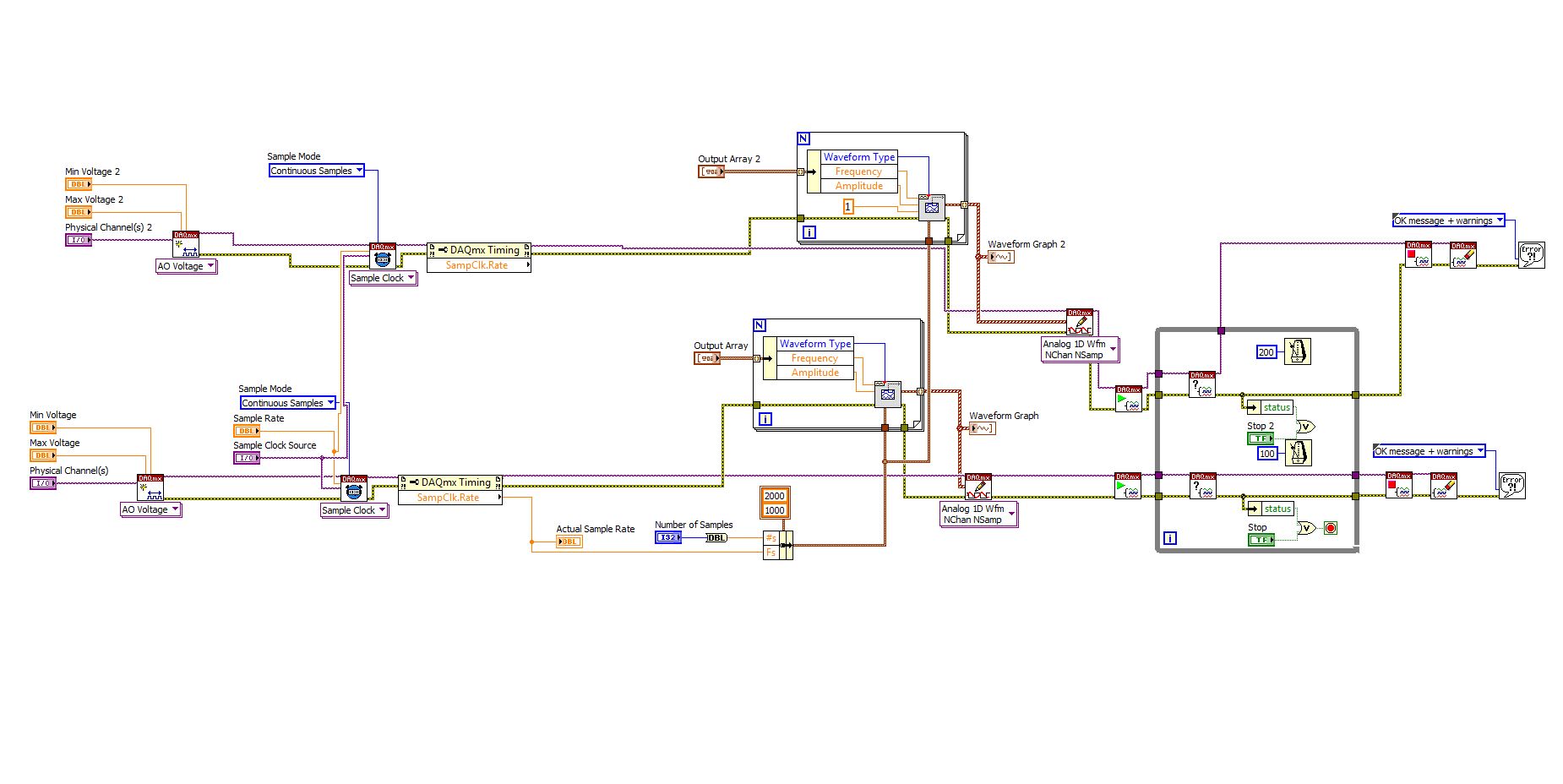
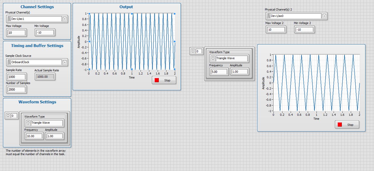
I'm new to LabVIEW and have some problems in DAQmx with control outputs analog multiple.
I want to set up a platform using BNC-2110 and PCIe6363 to control two rotating mirrors. The problem that I can only give an output (AO0 or AO1) at a time and I really have no idea how revise my LabVIEW diagram to control two outputs at the same time I met. I tried to change the outputs and it keeps a mirror turning instead of the old. Could someone help me with my problem and I would really appreciate. This is my blocked diagram and front.
Hi zrmaker,
As mentioned by RavensFan, you should not create 2 analog outputs different tasks if you use AO0 AO1. To your façade > physical control or the channels > select the drop-down list of the control channel physical (s) > Browse > hold down the CTRL + select the AO0 and AO1 > Select OK. Once this is done, you will see that your control or the physical channels has the following input values: "Dev1 / ao0:1" which means that you will access to AO0 AO1.
In regards to writing DAQmx, simply select Analog > multiple channels > samples multiple > 1 waveform (you should get the following: 1 d Analog Waveform NChan NSamp). Once done, you can just use table build to combine 2 different waveforms and plug in this table to DAQmx writing output. The first index will be the output for AO0 value and the other will be for AO1.
You can check this link on how to read or write from several channels: http://digital.ni.com/public.nsf/allkb/0C1ADEF06A54AB2D862575040066FD51
Additional reference:
http://www.NI.com/white-paper/2835/en/Hope that helps.
Warm greetings,
Lennard.C
-
analog output digital start trigger the api c
Hi, I'm trying to start analogue output based on a digital trigger (either PFIO or a PXI line) I can make this easy in LabVIEW. However with the C API (through the Python wrappers), the problem is when I call DAQmxBaseWriteAnalogF64, writing will always be timeout that the acquisition was not triggered. However, I can't call it after the trigger occurs, because obviously, it will be too late.
I can't find any examples of C API where the analog output is triggered a digital triggering. I can find for the analog input, but is fundamentally different that you can CONV read anytime after the trigger occurs.
Python code as follows (functions are equivalent ot C API, even if you have no need of ot pass the task handle such that it maintained as part of the Task object)
# create analog output task
analog_output = Task()
analog_output.CreateAOVoltageChan("Dev1/ao0","",-10.0,10.0, DAQmx_Val_Volts, None)
analog_output.CfgSampClkTiming("",outputRate, DAQmx_Val_Rising, DAQmx_Val_FiniteSamps, numSamples)
analog_output.CfgDigEdgeStartTrig("/Dev1/PFI0", DAQmx_Val_Rising)
analog_output.StartTask()
analog_output.WriteAnalogF64(numSampsPerChan=numSamples, autoStart=False,timeout=1.0, dataLayout=DAQmx_Val_GroupByChannel, writeArray=data, reserved=None, sampsPerChanWritten=byref(samplesWritten))print("Analog output: Wrote %d samples" % samplesWritten.value)# create digital trigger dig_out = Task()dig_out.CreateDOChan("Dev1/port0", "", DAQmx_Val_ChanForAllLines)

# create digital trigger function
highSamples = 1000
numpts = 3 * highSamples
doData = np.zeros((numpts,), dtype=np.uint32)
doData[highSamples:2*highSamples] =  2**32 - 1

# send digital trigger
doSamplesWritten = c_int32()
dig_out.WriteDigitalU32(numSampsPerChan=numpts, autoStart=True, timeout=1.0, dataLayout=DAQmx_Val_GroupByChannel, writeArray=doData, reserved=None, sampsPerChanWritten=byref(doSamplesWritten))
print("Digital output: Wrote %d samples" % doSamplesWritten.value)
Hi PatrickR,
You can review examples of code NI-DAQmx (ANSI C) text based on the production of an output using a trigger to start digital analog. If you included/checked support textual dusing your NI DAQmx driver installation, you can navigate to Windows start > all programs > National Instruments > NI DAQ > Teaxt-Based Code support > ANSI C examples > analog output > generate voltage > Mult Volt updates-Int Clk - Dig start. If you have questions/doubts about the material.
-
the time of acquisition of data - how to calculate the rate of analog output
I want to calculate an acceptable rate of analog output, one that is taken in charge by material (PCIe6353), without the rate being changed by the VI DAQmx Timing (sample clock). The final objective is to have a rate of analog output that is an integer multiple of the analog input for precise frequency, since the sinusoid AO's amplifiers, which have a ringtone when AO updates occur.
According to 27R8Q3YF of the knowledge base: how the actual scanning speed is determined when I specify the rate of scanning to My d..., the rate is revised as needed by calculating the rate of clock / asked for advice, divide the result rounded downwards and upwards in the clock of the Board and use the one that is closest to the requested speed.
If 'Embedded clock' is selected, which is the result "Council clock. DAQmx sample clock timebase Timing node - SampClk.Timebase.Rate says 100 ms/s. However, for a rate resulting from the update of 2.38095MS / s, the divisor of the time base timing node - "SampClk.TimebaseDiv" gives a value of 42. 42 x 2.38095 M = 99, 999, 990, where it should be 100 ms/s.
How to calculate an acceptable rate of analog output is supported by the hardware? I have other plates, in addition, a general method would be appreciated.
I haven't worked all the details yet but noticed a few things that may be relevant.
Req AI rate isn't a whole ditch 1E8. It is used to determine the rate of the AO.
There is no check to ensure that the rate of the AO is an integer division.
It seems that you have the right idea, but the implementation is not yet there.
Lynn
-
How to determine the number of highlight ' to write ' for DAQmx generate analog output?
On the configuration of the stage for DAQmx generate analog output, there is a field "value to write. I can't find any explanation for what it is, how it determines the value to enter, nor what he writes. I am trying to go through the tutorials and it cling.
Someone would give an explanation?
Hello
To write value specifies the value to write in the channels, lines or ports selected in string parameters. In other words, this value will be the value of your DC output (for example if you enter 5, your output will be 5V). To get information on different fields in SignalExpress, access help"context-sensitive help. A pane will appear in your work environment that displays the coordinates of the field when you place your pointer over them.
For new users of SignalExpress:
Generation of DC signals with NI DAQmx devices: step in the DAQmx build, select 1 sample (on request) in the generation Mode dropdown. You can select a programmatic input to generate, or you can remove the check mark from the check box use programmatic input and specify a value for generating in the field of value to write . NOR-DAQmx help also provides additional information about the data generation.
Best regards
M Ali
Technical sales engineer
National Instruments
-
DAQmx: Analog input directly to the analog output at the hardware level
Hi all
I searched for a while, but I couldn't find any suitable implementation for what I'm trying to do. A person where I work introduced me to an interesting challenge. Is there a way to set up a DAQmx task (or set up otherwise an MIO Board) to route an entry directly to an output to the analog analog hardware level? You may be thinking, "why the hell would you do? To reduce the electrical complexity, a colleague would like to concurrently read an entry while 'reproduction' of its signal on analog analog output. I know that I can easily accomplish this while the buffering by the PC, but they are interested in ensuring that the output signal is also similar to the input at the level of KHz signal, by introducing a minimal difference in phase (shift buffering of the PC).
For the record, we have for most old maps of the E series here like the PCI-6070E (PCI-MIO-16-1). I was first asked if it could be done through SCXI, but I figured I would start by asking about the MIO tips.
This looks like a long shot, and I've never heard of someone at - he never did this, but I thought I'd ask to be sure!
Thank you
Jim
Hi Jim,.
With the help of our driver is not a means of generating data directly from the FIFO of AI, it must first pass through the software. You can try the following code to the output of one of THE duplicate on the AO line to see what kind of delay you can imagine. It is similar to your original with a few adjustments code:
Use delayed output Version of avian influenza in DAQmx AO
It seems you need to do, you might consider instead the search by using a voltage follower to isolate the Vout wine.
Best regards
John
Maybe you are looking for
-
How do I cast to the ROKU?
-
S should mean Save. You can use B to save as a background. Right click + S became "connected" in my fingers after several years of use of IE. I don't know there are millions of users who feel the same way.
-
Satellite C850 - 1 4 - Win 8.1 don't pair with Android Tablet
Hi people, I tried to pair my notebook without success (my first try with BT).The notebook detects the PC and the password dialog box is displayed on the pc. I confirm and the Tablet indicates it is coupled. It's like he goes. There is no indication
-
With the evolution of the lines from outside the PXI-7831R problems
I have a map of PXI-7831R and I am an envelope in return (for automatic test) to a port on a connector to another port. Connector 1; Port 0 to Conn 1; Port 1. I send a pattern on port 0 and receive it on a port, it works. I then change the port 1 to
-
seeking a quiestion on weather or not the train game 2 the training organization supported my TIGER and apperently supported by microsoft and the gadget show. I had an assesment in my house who seemed very intriguing, I'm not sure how good this compa