How to wire NI 9203 to Emerson PT5 pressure transducer
Hi all
I started studying with 9188 OR cDAQ and analog input NI 9203 module. I'm really new on the DAQ hardware and I confused about my wiring for the NI 9203 pressure sensors. I want to use 6 pressure transducers whose output signals are ampere (4-20 my). In the manual operation of NI9203 shows that there is only 1 negative port (COM). Could I wire 1 more NI 9203 pressure sensors? If it is possible, how would I do that? The pressure transducers that I wanted to use a 2-wire and its technical specifications is Emerson PT5.
Hello
You should be able to branch out of the output of the power supply 24 VDC 8 drivers. Does that help?
-Carisa
Tags: NI Hardware
Similar Questions
-
How to wire connect portable air port extreme
How to wire connect high tower hp air port extreme?
Thanks for the help
Buy an Ethernet cable at your local electronics store. Connect one end to an Airport Extreme LAN port. Plug the other end into the Ethernet port on your laptop.
-
How to wire a pressure transducer loop 2 wires for the NI 9949 RJ - 50
I am new to the NC and data record.
I want to connect a 4/20mA, pressure sensor loop 2 son of a Terminal screw OR 9949 RJ - 50... that will then connect to an entrance NI 9237 module.
The NI 9237 module is installed in a chassis OR compact 9174 DAQ.
I shall be measure the pressures of air brakes truck to compressed air system of zero kPa (gauge pressure) up to allowance of 1000 kPa (gauge pressure).
The 2 wires on the transducer are identified as: food + and + signal
I would appreciate it please advice on the appropriate terminals on the NI 9949 RJ - 50
Unfortunately, it seems that you have the wrong module for this task. The 9237 is used to measure the production of bridge-based sensors (for example, a strain gauge). Signals that it is supposed to measure are fundamentally different from the 4-20mA signal pressure transducer outings.
Take a look at the NI 9203, 9207 or 9208. All have at least a few channels designed to take a current 4-20mA input. Then, give the team nor a (877-387-0015) call to talk through your application and make sure that you select the right equipment for what you want to do.
-
How to download music on my emerson mp3 player
I need to know how to download music to my emerson mp3 player .i bought used with no software.
Here is a source of downloadable Emerson mp3 manual player of the user who can help:http://portablemedia.manualsonline.com/manuals/mfg/emerson/emerson_mp3_player_product_list.html
-
Hello
I am completely new to LABVIEW software.
I learn a LABVIEW code existing my pressure (attached) acquisition system which has the path of data as follows: pressure transducer Validyne--> Validyne CD280 - Dual--> SCB - 68--> PCI - 6024E--> LABVIEW and I have a few question:
1. How does the complete system of the transducer to the LABVIEW work? That is, if we apply the pressure of the transducer, it will change the resistance of the probe then...?
2. How can I find the equation that expresses the relationship between the pressure and the tension to the keys of the Validyne double-CD280 in the LABVIEW?
3. If I want to do the probe calibration, what are steps?
Thank you
You did not include most of the subVIs.
-
I am trying to learn how over the state machine. I created this simple vi. The intention is to take the entry, and if it is less than 5, then the value squared. If it is greater than 5, then the value should be cut into cubes. However, I only get squared values. What is missing here? For a value greater than 5, I get the value "2" appears in the output area square... whence the 2?
NIquist beat me to the punch. I made this moification an got tied up before I could post it for you.
Unfortunately for you, these examples show only two States that do not help House by car at the point of a state machine. You can have several States to treat your data or move you your application.
I have developed your VI a little to show a few things. There are essentially 3 separate running in the loop state machines. The bottom is a simple example where to put your code based on what you need to do. Then you determine what state your data tells you to go to the next, and you may have several States here, not only two.
-
How to wire a switch terminal case and depending on this value string value, run a case selected?
Hello world
In the schema-block sent VI, through serial comm, #2 byte is 00 or 01 (Hex). This byte must dictate which cases to run. If value = 00 Hex running case #1, Hex if value = 01 runs the #2 case. If none of the two, nothing should run.
How can I do this? I'm relatively new to LabVIEW, any comment is appreciated.
Thank you
Mahir
easiest of all wiring in the whole structure of the case rather than convert to string.
Then just back up the case selector and type what you want.
-
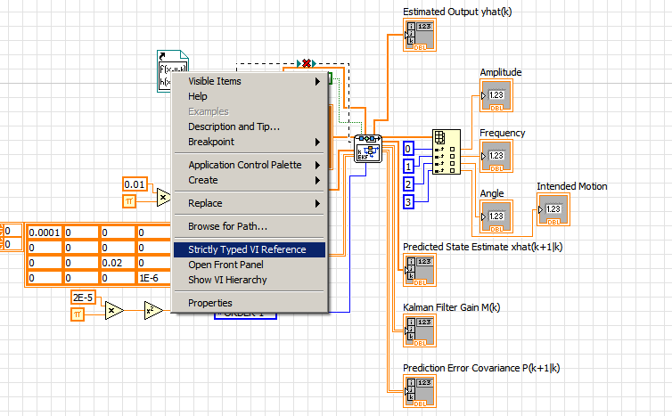
How to wire a model of factory reference in properly extended Kalman filter?
Hi guys,.
I have a problem using the Kalman filter lying on LV2009.
Whenever I run my program, my State is not updated by the function.
When I checked through, it seems that my model of plant somehow was not fully connected in the EKF vi.
Never change the value shown on the factory model.
The related vi (s) is attached. The acc_emg.vi is the main program.
It uses EKF to estimate the State of the parameter of earthquakes.
We hope you can give me some advice. Thank you very much.
Agus Frédéric
Nanyang Technological University Singapore
You can right-click on the static VI reference and select strictly Type
-
How to wire the NI 9422 module to an encoder?
Hello
I want to connect the NI9422 to an encoder.
The encoder data sheet is:
http://MDM.KPNO.NOAO.edu/TD/PDFs/bei/H25_Incremental_Encoder.PDF
Eager to help on this.
IM using cRIO 9024 and my encoder is BEI H25D-SS-512-ABC-7830-LED-EM16-S
Pinout for encoder is:
A > A
B > BC > -.
D > + 5VE > B -.
F > 0VG > matter on the ground.
Thank you.
R.H.Hello
I think you should use 9411 (http://sine.ni.com/nips/cds/view/p/lang/en/nid/208812) module because that differential digital inputs. Looks like you have the wrong module to use. Your incremental encoder has A +, A - and B +, B-requiring differential inputs. 9422 is a digital input module 8 channels for 24V to 60V input logic level, that does not meet your needs, and it is also not entered differential.
If you have the correct module, then perhaps you can visit this page to learn more?
http://www.NI.com/white-paper/3921/en
Rando
-
How to get mydaq recognize px309 pressure transducer % 3F
It has only 3 wires instead of the usual 4. They are black, red and white and negative excitement, positive excitement and signal respectively. I plugged the black wires and red to an external power supply, the white wire to the myDAQ HAVE. Then I went to labview, opened DQA assisntant - acquisition - tension - ai1. Then I put samples of continuous get ot and drew a graphical indicator and press the run button. Yet, the only signal I get is noise and graph (amplitude time vs) shows no change when pressure is applied.
Have you tried also runs the black wire from the transducer into one of the analog grounds on your MyDAQ? Measures data acquisition potential, without reference to ground the unit will not be able to measure anything.
You can also use an output on the analog MyDAQ to produce the voltage instead of using an external power supply.
I hope this helps.
-Nick-
-
How can I use other companion DAQmax and data acquisition in labview code?
Hello
I'm new in labview and want to combine four different codes of labview and run them at the same time.
I use my data acquisition PCI-6071E and BNC-2120. I want to send an analog output (flat DC signal) to control a blower, an analog volmetre to a (DC) output pressure transducer, also receive data from a pressure sensor and hot wire probe.
I wrote four different VI for each of them (using DAQmax to output analog and DAQ assistant for analog inputs) and each of them works well, but when I want to use them together they do not work.
Anyone know how to make them work together?
Thank you
Pooya
To the DAQ Assistant, simply follow the instructions for the selection of multiple channels when you create (where he says quite clearly,' '
or to select multiple channels "). If already created, open the DAQ Assistant and click on "Add channels" at the top of the page. When you use a physical channel name, you simply click on browse instead of a single channel. Use the same
or for multiple channels. -
Question on how to data field/table/graph xy
Hello-
I currently have a VI which reads in information through the DAQ Assistant, in two tables of waveform (load / time) and the displacement / time. I would like to be able to take this information and draw another (load vs displacement). I have converted the sets of dynamic data from the charts of waveform in both ways (load and displacement) and then them grouped in an array of clusters. I tried adding a waveform chart in the table of cluster, however it does not seem to be traced. (It is located in a loop so that it must constantly be updated because the control is underway.)
I would appeciate any help you may have. Please let me know if you have any questions.
Thank you for your time.
A graph is just simply not true, if you want to draw one table against another. This is what a XY chart is for. Just take your existing arrays and group them together. If you turn on the context-sensitive help (and it really takes on all the time) on the block diagram and move your mouse over the graph, it shows you exactly how to wire the data. Given a graph is a no story, you will need to implement if necessary. There is a graphic called example XY or just look for the Board of Directors. Many examples that use a couple of shift registers. The graph XY Express can be used as well.
Don't know why you want in a separate loop. Place it next to your written chart would make as much sense.
-
The wires for the Acer Iconia W510/W511 of power
Hello.
Is there anyone who had to take a closer look how the wires are connected to the 12V socket?
Reason is, I would use the tablet in my garden, where the only power is my solar cell / battery of 12V of the summer.
I know that I could rip it myself, but the Tablet is still under warranty, I think not only encouraged. Also I know that I can use a UPS, but a) my inverter is noisy and b) it's a bit silly to transform 12V-->--> 12V 220V
concerning
/ Henning
FYI here is a photo taken with my phone, as you can see just on the ground and Vout being on the ground, at the end of the connector,-, + as shown in the photo on the PSU should be child's play to hit something up.
-
I always get 0mA by what follows: I use a 9203 to measure the pressure of a PX-309 aroussia. The transducer has two wires, red and black. In Figure 3 in the NI 9203, I have connected the Red wire to a channel of AI on the 9203. The black wire is connected to one side (+) power to 30 VDC. The negative side of the power supply is connected to the Terminal on the COM. 9203
Two other channels works fine. They come directly from an analog output 9265.
In DAQmx channels (from 9265) are open with a channel to create, and the only channel (from PX - 309) opens with its own channel to create.
Any ideas about my problem here?
It worked! Thanks a lot for your answer.
-
How can I make orders save their State when the project is closed?
I am currently working on the program for a compact RIO which will be used with a variety of instruments. Some data on each of these instruments calibration must be entered into the program via the controls on the front panel, so they can produce the correct value (for example, the input range and a pressure transducer units are required for the program to a scale of 4-20 my reading in a pressure reading).
The problem that I am running is that, every time I close the project and open it again, all calibration checks back to their default value. What I want to do is to save their State whenever the program is closed so that if you reopen the project without changing the material you don't have to re-enter the calibration values. Can someone tell me how this can be done automatically?
I know that this can be done manually by saying to each control to set the current value to its default value, but I'd rather not have to do whenever we change the calibration constants. Ideally, the user does not have to use the context menus like this.
Maybe you are looking for
-
Re: Toshiba Recovery software download
I tried going through the F8 option and go to the recovery screen. When I access the menu options it does not give me the option to "TOSHIBA HDD Recovery" just the normal windows. I spoke with TOSHIBA who think that the recovery folder has been delet
-
Neden bir sonraki sefere Apple edilen ki edeyim?
Merhabalar, 17 Kasım tarihli İmac siparişim Island iligili yaşadığım paylaşma ihtiyacı duydum problemi. Umarım benim ve customer hizmetlerindeki arkadaşların tum cabalarına rağmen varolan prosedurun bu konuda bir Çözüm bu getirememesine paylaşımım ya
-
Hello I ordered a cRIO-9073 with several modules for a project in the short term, but it will not happen in time. I can see that this material can be faked in the traget FPGA. Can it also be simulated as target RT? -For use with LabVIEW RT. Thanks in
-
Why icons keep appearing in the notification area when I checked "hide when it is idle? '?
I only see "Volume" and "McAfee" after I restarted, because they are the only ones I selected for the show.
-
Photosmart Premium C309G Linux compatible?
Is the HP Photosmart Premium C309G printer compatible with Linux? Compatibility Linux is a test before I buy a printer, and I'm curious to know. I note that similar (but not identical) model C309A is compatible, as shown here: http://hplipopensource