I can measure the speed of the NI 9401 fan & cRIO 9075 under Scan Interface?
Hello
I am currently using OR 9401 & cRIO 9075 to develop a project, which is to control the CPU fans.
Since I have to communicate with other instruments by serial port, while I have a NI 9870 module to implement the instrument control.
I finished the part of control instrument under scan mode and would like to add the function of the fan speed reading.
Now, I wonder if there is a problem when I choose the Scan Interface to deverlop the program.
I found the following tutorial, he uses the FPGA interface to impement the acquisition of control and PWM frequency.
http://www.NI.com/white-paper/3230/en/
So if the function of the fan control only developed under an FPGA interface, I have to rewrite the control instrument part, seems to be a bit complicated...
You can use the hybrid mode.
http://digital.NI.com/public.nsf/allkb/0DB7FEF37C26AF85862575C400531690
Tags: NI Hardware
Similar Questions
-
How can I use 2530 b and 4065 to measure the resistance between two selected pins?
I want to be able to select 2 corners on a test with 2530 b set-up and measure the resistance between them with a 4065 DMM (PXI all). Ankles in question are each in blocks of 32 different poles, so I can match them in a double configuration 32 x 1 four or 64 x 1 if necessary. I can measure the resistance between several different pine sets as 0 on 33 pine pine, pin 0 at pin 34 pin 0 to 35 pin and pin 1 to 34 pin, pin 1 pin 36, etc.
I understand how to measure resistance between a given pin and Earth using the the 2530 4065/b using the wizard OR-DMM/Switch Express, but it is unclear if I can measure the resistance between the two pins of selected by different user. I am a newbie of labview, used to write things in c#, so it may be something very trivial (I hope).
Any ideas?
Thank you
-Russ
Hey Russ,.
I recommend starting with the following example (located in the Finder the example ('Help' to find examples):)
"" Material input and output"Modular Instruments ' OR-Switch" niSwitch Dmm Switch Handshaking.viBecause you use a scan list, you can simply drag the two connections to the same entry and then the switch will wait for the two to settle before you send a trigger of the DMM... problem solved. For example, to connect the CH1 to Com0 (DMM +) and CH93 to Com4 (DMM), then take a measure, then connect CH38 and CH120 to the DMM, you would use the entry list of scan to the following address:
CH1-> com0 & ch93-> com4; CH38-> com0 & ch120-> com4;
Note You can have as an entry in list of switch module scan. In addition, you can only have a single advanced analysis and a measure full per switch module.
-
Measure the time in seconds each time run you a VI
Dear people,
I'm trying to measure the speed of a wheel using a magnetic sensor and other settings in the vehicle. What I also need to document in my project is the time elapsed (in seconds) each time that you run the program. Is there a way where you can measure the elapsed time in seconds in labview?
Any sort of suggestions or examples would be useful.
Below is an example of how I wanted my final to watch output file.
Time (sec) | Speed (mph). Acceleration |
0 23 5
1 24 6
2 25 7
Thank you in advance!
Rahul-
Hi iZACHdx,
That's what I was looking for exactly! Thanks for the simple example.
Thank you
Piraux
-
measure the temprature of thermistor using 6225
Hello
I'm using LabVIEW 8.6/DAQmx with a DAQ card 6225 of series M, connected to a terminal block of CB_68LPR. I want to measure the temperature of a thermistor.
First of all, I connect the two wires of the thermistor to AI6 (J25) and HAVE GND (J24) because I assigned AI0 to Ai5 to six voltage signals.
When I tried the example of temperature measurement, if I set up the channel as "2-Wire thermistor Iex" ai6 and choose the internal excitation source, I got the error message "measurements: device to which is attached the sensor was not a source of excitation internal avaible. But the requirement for this example indicates that the PXI-6225 can run the example. So here are my questions: is not my connection reflectometers to the terminal block? Which device should provide the excitation source, the map DAQ or other Terminal, if I really want to choose internal source?
Then I tried to use DAQ Assistant to configure the channel as "Vex 2-Wire thermistor" ai6, I received the error message "measurements: configuration 2 son resistance is not compatible with the excitement of tension", no matter if I choose 'Internal' or external"source of excitement." But in general configuration 2 son is good for thermistor. So my thermistor is not the type thermistor Vex? So, what type of thermistor is Vex thermistor? The technical details of my probe says nothing if it is Vex or type Iex.
Thanks in advance,
Caizhen
Hello Caizhen
PCI-6225 doesnot have an internal excitation source, but you can use one of the AO as an excitation lines if you have not the external voltage source, in this case, you should always configure your task as external excitation and measures four sons and in the program, you can take care of task AO where you can specify what exciatation you need. The measure of two sons is not supported in Vex-thermistor task. The connection diagram is shown in Measurement & Automation Explorer (MAX) in your task DAQmx.
Another possibility is to you can measure the resistance of the thermistor and map it to the temperature at two scales, but you will still need to have the excitement of current external OR-6225 has not built in power source, which is what he does in the task of Iex-thermistor.
Keep us informed on updates.
Thank you
nAyer
-
How to use photoshop to measure the amount of shades of Brown in a given area (Immunohistochemistry)
I try to use photoshop measure intensity area of brownish (some variance) in a part of the image of a mouse knee joint. I have stained a particular marker in these samples and hoped I could quantify because she is extracellular and discreet
Thank you!
Scott, I believe that I came up with a way for you to make selections within your settings and have prepared an example to demonstrate the method. Much depends on whether this technique, using your spot color and a specimen, will work. If so, you can measure the number of pixels in the selection following the instructions I provided previously. Here goes:
1. This sample represents the darker brown spot.

2 build a scale of gray similar to this (I can provide one shown here)

3 Edition > fill with your Brown sample more dark and set its blend Mode to color. (When I used the sample in step 1, this was the result.)

4 attach it to your specimen as shown image file here. (I have not colorized that half of the test image to demonstrate the next step only select the sample Brown even if the black & white area has the same tone value.)

5. with the magic wand, a tolerance of zero and contiguous unchecked value, when you click on a box in the balance its corresponding value will be selected in the image. Here is an example. The histogram can then be used for a number of pixels from all selected areas. Repeat for each sample in your settings.

I hope it does the job for you.
[(Edit: quand vous arrivez àles valeurs plus sombres, vous pouvez constater qu'augmenter la tolérance contribue à la couverture de l'écart entre valeurs.)]
-
Measure Z to a battery encoder encoder pulse frequency to measure the speed using a 6034 E card
Hello
I want to measure the speed of a motor that has an encoder to encoder hung on battery. It provides impulses 3 A, B and Z I uses a PXI 6034 E card. I wanted to know if there are any examples/ideas that could help me with this (I'm new to digital programming in Labview). I moved to NI Daqmx 9.8 recently of the old version that has supported the existing codes and therefore being updated the code. I also want to know if an external clock source is needed to do this. This.
Hello
There are several examples in the finder OR example (you can get here by going to help > find examples in a window of LabVIEW). You can browse examples of Encoder on input and output material > DAQmx > entry counter. You should be able to find some examples that will be useful.
In addition, this link is a good resource to get started using DAQmx: http://www.ni.com/white-paper/5438/en
Thank you!
-
measure the speed of the fan in box vibration Simulator
I'm trying to measure the analog speed towards the sbRIO
I get a few signals pulse switching to 5v to 0v and vice versa with variable duty cycle...
How can I calculate the speed of the fan
values provided on the box of Simulator are
Tach 2 pulses/revolution
the maximum speed is 6,000 rpm
Please help me with this...
Did you look at the examples of LabVIEW? If you have installed the OR-DAQmx driver, you will find many examples showing how to do the counting of events or measures of frequency.
-
Measure the speed of download of modem broadband
Can someone advise me how to measure the real speed of downloading on my mobile broadband after any time. I would like to know how many Mbps, he realizes in fact, and not what the camera is capable of.
Use the performance monitor on my PC?
The operating system is Win 7 Home Premium, 64-bit
Thank you very much
Chris
One of the many linkages
-
Change of modem can improve the speed of Airport Express Extender?
My router is a Airport Extreme 6th Gen.
When Wi - Fi and close this Airport Extreme base station, I get average speeds of:
117 Mbps down and > 11 Mbps upward
At the opposite end of the House, I use a wireless extension: Airport Express 1 St gen - model A1264 (MB32 1LL/A)
Here, the download speed goes up to 14mbps .
Download speed rest > 11 Mbps
My ISP will not have my current cable modem: 6580 Motorola (jumpered to disable router) to provide speeds greater than 100/10 (though even I can actually slightly higher than average, I have indicate above).
If I replaced the modem with my ISP (Time Warner Cable) provisions for 200/20Mbps (speeds I pay in fact) - and * if * I got then that 100 Mbps speed increase (wireless) when close to my Airport Extreme base station (and I think I'll) - should I then expect to see a significant speed increase at the opposite end of the House , where I rely on the Airport Express wireless extension?
In other words, is expected to double the speed of my modem now gives me wireless (when you're on my Apple Extreme base station) also be reflected in an increase in speed at the end of the House where I must rely on the Express Extender 1 generation and where I am now only download speeds see 14Mbps?
BTW:
1. I can not move my extreme or my Express. They both must stay exactly where they are. Neither can they cannot be permanently interconnected via ethernet cable.
2. I don't think the speed reduction I describe is a bandwidth issue because I am the only one on the network and do not have multiple downloads on several devices at the same time.
Before I ring $$$ on a modem that won't improve my speed, you will appreciate any guidance I where I need more.
Change of modem can improve the speed of AirPort Express Extender?
Just a little, at best. The Express pourrait spend 25-30 Mbps. No guarantee, with strangeness wireless... it is maybe the same or worse based on my experiences.
If you need more speed at the end of the House... the AirPort Express must be located to half way between the AirPort Extreme and the end of the House. Ideally, he would have line-of-sight with AirPort Extreme.
Yet, you say that you can not move the Express or the extreme and can't get the Ethernet cable. Have you considered or tried Powerline Ethernet adapters?
-
How can I measure the variable tension with the DMM and switch?
Hello, engineer,
I am a student, I want to measure the varying tensions from V to Via. I have the following equipment: SMU-1065 PXI-4065 PXI-2529. I use the PXI-8360 and PXI-8361 to connect with my PC. I hope I can do that when I have the next blood I should click with the mouse and connect the right position to the object of measurement.
How can I achieve that?
Any suggestions with great satisfaction.
Since I know a little English, if I did not explain my question clearly, please ask me.
Best wishes.
Kind regards.
chuanyuehuoxian
Yes, you can.
You can set the samples when using DMM.
You can also refer to the example in LabVIEW.
THX!
-
How to measure the angular velocity, the angle and trigger using a gyroscopic sensor breakout board and LabView data acquisition?
There is a single channel data acquisition code which measures the angular velocity, angle and flexibility using a gyroscopic sensor breakout board and acquisition of LabView data attached to this, I need a help to creat two-channel data acquisition code?
Hello
Attached is a vi that you can use in order to read the measured angular position of an encoder.
If you need more examples on the tasks that you can develop with NOR-DAQmx and LabVIEW, you just need to open LabVIEW and click Help > find examples > Input and Output material > DAQmx > entry counter.
Kind regards
-
How can I measure the output of a sensor pwm ultrasound using the module or 9403
How can I measure the output of a sensor pwm ultrasound using the module or 9403
Khalil,
When you say 'measure' the PWM signal, exactly what to tell you?
You're looking to measure the frequency or cycle of the signal function? You count the edges of the PWM output increase? Looking to control the waveform?
With reconfigurable FPGA hardware, it is up to the user to define the function of the physical i/o on the FPGA chip. By connecting the signals as Adam suggests your digital pulse will be brought to the cRIO. In your FPGA program, you define the function. You can set a base counter or transfer digital data from single point to welcome you cRIO for floating-point more complex treatment. Example FPGA programs are located in the http://www.ni.com/IPnet.
Hope this helps, please post any additional questions.
-
How can I measure the Max delay
Hi guys,.
I'm trying to add the module to the pulse to my VI. To do this, I guess I need to measure delay Max.
In my class VI, I have some instruments of the current driver, LED, spectrometer, camera and temperature controller. In addition, current is the variable I can change all the time during the execution of the VI.
I was wondering how can I measure the delay between the one and the other, and when I change the value of the current, how long will take to capture the right data
I knew that the number of cycles to measure VI all the time but how can I do for several parts
Thank you
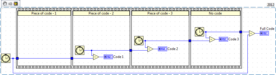
Time required for the execution of some code can be done using 'Tick counts' now if you do not want it for full code but you want for specific elements of the code, then you must use the same function (i.e. "Tick count" separately for each section of the code.
-
How can I measure the time between the two edges of successive increase, using digital input...
Hello
I'm trying to measure the time in seconds between each two successive rising edges on a digital input.
So far I managed to detect the rising edge, increment a counter at each rising edge and take the time during which the increase is edge
all I need now is subtract edge currently rising from the previous era of edge rising to calculate (T), which can be 1/frequency and display in real time for the user.
but I do not know how to do this

Can someone help me please!
Note: while I am in a position varies between 200 ms - 2 seconds
-
How can I measure the time between each two successive increase edges, using digital input?
Hello
I have tried two measure the time in seconds between each two successive rising edges on a digital input.
So far I managed to detect the rising edge, increment a counter at each rising edge and take the time during which the increase is edge
all I need now is subtract edge currently rising from the previous era of edge rising to calculate (T), which can be 1/frequency and display in real time for the user.
but I do not know how to do this
Can someone help me please!
Woah!

Sorry Apok, but your code becomes much too complicated and salty. I don't think that all records to offset or Boolean conversion/operators are necessary at all.
If you want to measure the time between two keys so it's another (much less complicated) way. It simply records the time when press button in a registry change, then compares the two.


Maybe you are looking for
-
Free Windows 7 Upgrade for Toshiba laptops
All have a Toshiba laptop and businesses more / another update for free http://www.toshibadirect.com/TD/B2C/ebtext.to?page=Windows7Upgrade&cm_sp=SpecialOffers Page-_-Windows7Upgrade-_-LaptopAccy3_shop
-
Recently, I checked WindowsUpdate.log my computer, I have continued to see the next line of the FATAL error writing here whenever I start the computer and about to close. He said something like this: 2010-07-29 00:56:47:906 1156 4 c 0 Misc = logging
-
MD3000i individual physical disk - gradient path
Recently, we have replaced a failing in our MD3000i HARD drive. After letting it rebuild, all the disks are again in an optimal state. But the recovery guru still gives this error: Individual physical disk - gradient pathGradient of physical disk pat
-
create the http client to retrieve data from web service
Hello I am newbie on our webworks. I need to retrieve data from web service. How to connect to this service and analyzed. There is a tutorial that can help me get started with it. Can any one advice me how can I start working with webworks on blackbe
-
Had my phone for 2 weeks and no problem. This morning the phone will not work. It is in the off position. Everything else is fine. Any ideas?