I2C implementation using NOR-6008
Hello world
I have a NOR-6008 low cost multifunction data acquisition.
Can I use this with shifter voltage level to apply the I2C Protocol...
You must use the approach of bit - strike (i.e., change you the clock and data lines yourself) and it would be timed by the software. But yes, you could do.
Your next question will be: are there examples? There are many examples on the conduct of IO digital who settle with DAQmx. Regarding the implementation of I2C, the spec is available. http://en.Wikipedia.org/wiki/I%C2%B2C
Tags: NI Software
Similar Questions
-
problem with loopback test base with NOR-6008
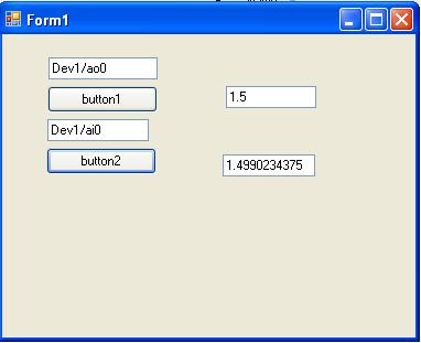
I recently started to use DAQmx in c# .NET 4.0 with NOR-6008 USB DAQ. I tried a loopback test by connecting output to an analog input analog and tried readign the signal from the output to the entrance but did not send the signal (or maybe a problem with the code). The analog input readign reads a random value rather than the value entered by the user for the output. I connected ao0 and ai3 on data acquisition. Here's the code.
private void button1_Click (object sender, EventArgs e)
{
Task analogOutTask = newTask();
AOChannel myAOChannel = analogOutTask.AOChannels.CreateVoltageChannel ("Dev1/ao0", "myAOChannel", 0, 5, AOVoltageUnits.Volts);
AnalogSingleChannelWriter writer = newAnalogSingleChannelWriter (analogOutTask.Stream);
Double analogDataOut;
analogDataOut = Convert.ToDouble (AnalogOut.Text);
writer. WriteSingleSample (analogDataOut, true);
}
Private Sub button2_Click (ByVal sender As Object, EventArgs e)
{
Task analogInTask = newTask();
AIChannel myAIChannel = analogInTask.AIChannels.CreateVoltageChannel ("Dev1/ai3", "myAIChannel", AITerminalConfiguration.Differential, 0, 5, AIVoltageUnits.Volts);
AnalogSingleChannelReader reader = newAnalogSingleChannelReader (analogInTask.Stream);
Double analogDataIn is reader. ReadSingleSample();
AnalogIn.Text = analogDataIn.ToString ();
}
Hello
I built an application using your code (with task.verify) and it works beautifully.
Have you tried different channels of inputs/outputs?
Curt
-
NOR-6008 selection file Matlab .m voltage range
Hi, I need to select a range of power such as - 1V to + 1V file .m in MATLAB to acquire data of acquisition of data NOR-6008.
I appreciate if someone can send me a code example.
The system works very well and I can control successfully the sampling frequency, but not the voltage range.
Concerning
Hello
The two alternatives are equivalent, option 2 is how to get to a channel if you had not registered to a variable when it is created.
When you say that it doesn't work, do you have an error message?
I just tried it on my machine with an NI USB-6008 with 4 channels and the range set to-1 [1] on one of these channels:
> s = daq.createSession('ni')
s =.
Session data using National Instruments hardware acquisition:
Will work for 1 second (1000 scans) to 1,000 scans/second.
Some channels have been added.> s.addAnalogInputChannel ('dev2', 0:3, "voltage")
years =
Session data using National Instruments hardware acquisition:
Will work for 1 second (1000 scans) to 1,000 scans/second.
Number of channels: 4
index of Type channel MeasurementType range nom_peripherique
----- ---- ------ ------- --------------- ---------------- ----
1 THE Dev2 ai0 (Diff) voltage-20 to + 20 v
2 THE Dev2 ai1 voltage (Diff)-20 to + 20 v
3 THE Dev2 ai2 voltage (Diff)-20 to + 20 v
4 THE Dev2 ai3 voltage (Diff)-20 to + 20 v> s.Channels (2). Range = [1-1]
s =.
Session data using National Instruments hardware acquisition:
Will work for 1 second (1000 scans) to 1,000 scans/second.
Number of channels: 4
index of Type channel MeasurementType range nom_peripherique
----- ---- ------ ------- --------------- ------------------ ----
1 THE Dev2 ai0 (Diff) voltage-20 to + 20 v
2 THE Dev2 ai1 voltage (Diff) - 1.0 to + 1.0 v
3 THE Dev2 ai2 voltage (Diff)-20 to + 20 v
4 THE Dev2 ai3 voltage (Diff)-20 to + 20 v
Properties, methods, events> s.inputSingleScan
years =
-0.0034 0.0008 0,0059 0.0012
Wael Bruno
The MathWorks
-
A better way to make a continuous read/write on a NOR-6008
Hello
I use a USB of NOR-6008 module and have a loop of the software configuration where I acquire analog signals, digital signals, then, then put a digital high or low and repeat. I use digital multiplex outside the material so that I can use 6 of the analog inputs to read 12 signals. The digital inputs that I have are connected to the buttons on a panel that are used for the entry instead of the screen of the computer of the user. My loop is also to build a buffer zone of all the signals on the analog and digital lines that I read in so I can on average and this process elsewhere in the program.
The question that I am running is because this loop is very slow and on the final product is performed on a touch screen, XP Embedded PC and just this acquisition loop begins again as much CPU as the rest of my program. I would say that drops of loops on 4 or 5 cycles per second, which means that my update of 2 multiplex signals or longer than a second time. I would really like to better performance and does not use as much of my CPU resources.
I use a way simple enough to make the loop of the acquisition, by setting the parameters I, reading, deleting the task, defining the parameters DI, read, erase the task and then by setting the parameters, write about it and delete the task, which gives a slight delay and repeat.
Any thoughts on a better way to start the read/write that what I'm doing?
I have attached the code examples in the loop of the acquisition that I use.
Thank you!
First of all, the best plan is to move the chain DAQmx before the loop to create and use a start DAQmx, then write in the loop, then clear once the loop ends. This configuration must be done once, not every time you write the channel. This should speed things up considerably.
-
How can I create a Windows using NOR-DAQmx application in Visual Studio 2010 64-bit
Hello
How can I create a Windows using NOR-DAQmx application in Visual Studio 2010 64-bit?
I'm transferring a 32-bit application on 64-bit. In visual Studio, I added the 64-bit project configuration. He compiled the source very well but the reports link errors:
error LNK2019: unresolved external symbol DAQmxReadAnalogF64 referenced in function NI6008_AnalogInput NI_6281\NI6281.obj
error LNK2019: unresolved external symbol DAQmxCreateAIVoltageChan referenced in function NI6008_AnalogInput NI_6281\NI6281.obj
error LNK2019: unresolved external symbol DAQmxReadDigitalLines referenced in function NI6008_DigitalInput NI_6281\NI6281.obj
error LNK2019: unresolved external symbol DAQmxCreateDIChan referenced in function NI6008_DigitalInput NI_6281\NI6281.obj
error LNK2019: unresolved external symbol DAQmxWriteDigitalLines referenced in function NI6008_DigitalOutput NI_6281\NI6281.obj
error LNK2019: unresolved external symbol DAQmxCreateDOChan referenced in function NI6008_DigitalOutput NI_6281\NI6281.objThese, of course, are the functions OR that I use. The NIDAQmx.lib has been added to the Input of the link property.
Any help would be appreciated.
Thank you
-Neil shore
Hi LaserShore,
Think you that you added the 64-bit platform settings target according to this page? : http://zone.ni.com/reference/en-XX/help/372636F-01/mstudiowebhelp/html/64bitcore/
Already running 32-bit application? Have you changed references to the 64-bit version?
You use Measurement Studio? If so some features are not supported with 64 bit.
Also when you say that you have added the NIDAQmx.lib, did you follow this KB:http://digital.ni.com/public.nsf/allkb/38F67B28D995C6958625706E000C580C
-
I'm trying to use a NOR-USB-6221 to implement SPI in a C++ application. When I try to configure a digital output task that uses ctr0 as the clock, I get an error stating that 'Sample clock' is not supported and use instead "on demand". I would be able to use the NOR-6221 and if so how to do this? Thank you.
Hi IntAndTest,
Maybe silly question: are you sure that you have a USB-6221 and not a USB-6212? The USB-6221 supports clocked DIO, but the USB-6212 is not working.
A problem with your code: when you specify a terminal DAQmx name, it must be is compared to the device (such as 'Ctr0InternalOutput', "AI/SampleClock" or "PFI0") or contains a slash before the device name (like "/ Dev1/Ctr0InternalOutput", "/ Dev1/AI/SampleClock ', or ' Dev1 / / PFI0"). This does not apply to the names of physical channel (like ' Dev1/port0' or "Dev1/ctr0").
The error is returned from code that you have not displayed? Your says error message DAQmxCreateDIChan failed, but the code you posted does not call this function. In addition, I don't see a call to DAQmxStartTask or DAQmxWriteDigitalU8, U16, U32, whatever.
Also, what NOR-DAQmx version are you using?
Brad
-
How to implement Canopen on FPGA to run the engine using NOR-9881?
Dear,
Your support will be highly appreciated,
There is only one available for NOR-9881 example.
Please note that the following materials were properly connected:
cRIO-9024, cRIO-9113, OR-9881 and motor Nanotec (SMCI36 against L2818L0604-T5X5), the following
sites Web shows the engine Nanotec in details:
http://us.Nanotec.com/products/660-L28-linear-actuators-with-trapezoid-spindle/
http://us.Nanotec.com/products/1041-SMCI36-stepper-motor-and-BLDC-motor-position ing-control /
The main problem is how to configure the inputs and outputs, where, in most examples, the entry and exit have been automatically
configured.
the following three examples and I wonder how to start:1 - example Nanotec: dependent VISA controls for data transfer
http://us.Nanotec.com/support/application-notes/LabVIEW-example/
2 - reference example CANopen for series C OR - 9853 Module CAN:
the NOR-9853 has default Can0 which was used in the codehttp://zone.NI.com/DevZone/CDA/EPD/p/ID/6093
3 - from finder labView example: search for 9881 then choose
NOR - CANopen_cRIO.lvproj, which depended on SDO orders for transfer orders
The attached picture shows that NEITHER-9881 can be seen, after compilation and
loading the bitfile FPGA.
Please, please advice me:
1. how to start?
2. how to create variables of entry for NI9881?
3. how to implement CANopen mode FPGA? where there is no CANopen palette.Thanks in advance and
Hello!
From my understanding, the 9881 can be treated from the FPGA, but only from the application of the RT. I think that the point 3 of your post examples of the use of the module fine.
Kind regards
Georg
-
How to define logical tristate using NOR-DAQ 6212 in c#
Hello world
I am very new to NOR & help each of you experts out there.
As the subject says, I'm trying to set digital output at tristate DAQmx & c# channel. I found the link on the Tristate property, but I don't know how to use it. http://zone.NI.com/reference/en-XX/help/370473H-01/mstudiowebhelp/HTML/bd33b0d/
Any help would be much appreciated!
Thank you.
Hi kasrus,
You set the property using the following syntax (after creating your task):
digitalWriteTask.DOChannels.All.Tristate = true;
As help document states: "you must commit the task for this setting to take effect." The help document also highlights when the value of property compared to a reading or writing.
This refers to the status of task template DAQmx:
State of task model
http://zone.NI.com/reference/en-XX/help/370466AC-01/mxcncpts/taskstatemodel/
Methods of configuration will move your task through this model of the State, but you can also control using the syntax in the article below:
Check, committing, start and stop of NOR-DAQmx tasks programmatically
http://zone.NI.com/reference/en-XX/help/370473H-01/mstudiowebhelp/HTML/verifycommitstartstopdaqtask/
Kind regards
Kyle S.
Technical sales engineer
National Instruments
-
Generation of pulses using NOR-PXI-5421 FGen
Hello Sir/Madam,
Question:
We use the Funktiongenerator NOR-PXI-5421 and just want to generate a pulse, because it can be done in almost all cheap Funktiongenerator.
Unfortunately, I can't find a way to tell the Funktiongenerator to generate a pulse. I can generate Singals as I like, but don't know how to generate a single pulse.
Perhaps you have a program that gives me this opportunity.
Thank you for your support.
Hi Jens,
You can try to use the Council 5421 scripts. The following examples of LabVIEW: "Fgen Arb Script.vi" or 'Fgen switch between Waveforms.vi' use of script to generate signals, you can create a script that generates a single DC pulse of high level in the same way.
I hope this information helps you.
Best regards
Blase
-
order bipolar motors with usb DAC-NOR-6008
Hi, I need help for an example vi that explaining how to order two bipolar stepper motors using the USB-OR-6008 data acquisition card, I have the engine drivers, can any body help me?
you are more than welcome... OK, I've attached a vi that could help you... I will illustrate how to connect your driver for your usb data acquisition card.
1. on the digital I / side P O/P of data acquisition is a 5V pin, connect it to the two 5V pins (pulse and Direction) of the driver.
2 - 2 other pins (Pul - and Dir-) connect to port0/$line0 Pul-and port0 / line1 to dir. (you can configure the ports like u as in the vi block diagram window).
3. allow the PIN to activate it without a connection. (it is normally activated).
for the connection of the motor: (do not connect these pins for data acquisition)
It has 6 pins.
first of all, you must know the motor coils wires, you could test with any counter AVO.
1 - the first pin is connected to the mass of the battery.
2 - the second pin to the positive pole of the battery.
3, 4 the first whorl.
5, 6 the second coil.
Try it and I hope that I helped you, tell me if it worked.
-
Design practice nor 6008 USB DAQ
Hello
I have a few question, I'd like to introduce. I need some sort of indication on how to better perform a timed cycle of acquisition driven by WSF.
I'll send my VI (conceptual, not one currently working one) and ask for explanations.
The goalI need to acquire a battery voltage. Load current consumption is driven by a couple of transistor. I drive the hollow transistors two digital i/o for USB data acquisition.
Because I need to have a power for a given time cycle, I need to have some sort of time control on the output.
So I wrote a simple state machine whose States are updated when a timer reaches zero. Each State has its own queue time.
Moreover, I differentiate between acquisition and control operations using two all in cycles.
First question: is this a correct way to a timed WSF of construction?and now:
The problem (s):
I need to connect and establish a correlation between the input line for the internal of the fsm States. So I madesome digital indicator on the face before of the VI and created a local variable (I know that local variables are BAD, but I had no other idea everything) to pass values for some time to the other.
I also want to select State sequent of the FMS based on the input value, I get a channel. I can stil use a local variable?
Are the two related tasks?
Second question: are local variables, something that I can use for this task?
Last but not least: I need to filter on the values.
In this vi I perform a filtering operation and then I get the I use for control of local variables.will be this filtering desync the two cycles while? will I run out of control before running the filtering?
The same question is valid for the purposes of registration: the unfiltered data record, I guess is unnecessary. But based on this 'architecture' I know the country reports and the recorded signals are out of sync (as happens in many game data acquired with this vi).
Is this a problem of logging (perhaps given by different buffers for data acquisition and internal State or something similar) or the whole WSF will be out of sync, then all acquired data is more useful because it is out of sync?Any advice would be much appreciated.
Best regards
Luca.
Luca,
Question 1: This is a reasonable start but need some things to make it a good WSF. There is no waiting or delay in the loop so it will run as fast as possible. U.S.-6008 outputs digital software timed so that the DAQ Assistant can take a long time, but the amount of time is unknown and not necessarily consistent from iteration to iteration. Since the DAQ Assistant Analog Input in the other races of loop to<= 10="" iterations="" per="" second,="" a="" wait="" of="" 100="" ms="" in="" the="" fsm="" loop="" seems="" like="" a="" good="" starting="" point.="" waiting="" 3000="" ms="" is="" not="" a="" good="" idea="" because="" the="" loop="" becomes="" unresponsive="" to="" the="" stop="" button="" for="" long="">
Do you need to write on the lines on each iteration, even when the data has not changed? Add a write state that is called only when the data changes.
The DAQ Assistant has a Stop input and an output of Stopped. When you are ready to stop the loop, the stop signal must be wired to these inputs so that the DAQ Assistant can delete tasks. The output of the order can be connected to a Terminal to stop the loop.
Problem (s):
It seems that you want to link the two loops. Local variables are usually a bad way to do it. The best way is to use queues. A queue can send the current state of the file loop. (More comments later if that's really what you need). Another line can send data, or better, the commands, the loop of the file to the loop.
I think you want digital output values rather than the State. Especially if you add a State writing as I suggested above, the current state will not always represent the condition of the power of your test. To make this work with the additional state Boolean matrix must be moved from one iteration to another via a shift register.
It seems that you have at least two controls to be sent from the loop of the file to the loop. One is the stop command. The other went to the higher power level control. You should probably have a command to set off power level which can be used if the battery voltage becomes too low and before stopping. How your program is currently configured, the last level of power will continue as long as the power of the computer is on and the USB-6008 is always plugged. The cessation program does NOT reset the lines.
When you use anti-parallel to the queues, you must be careful on the definition of wait times and the timed out case management.
The benefits of the queues are that it is easy to ensure synchronization at the level you need, the data can be stored according to the needs, and there are good examples. It also avoids the possibilities of race conditions, often introduced by local variables. This program could be based on a variation of the design producer/consumer model.
Filter questions: any filter introduces a time delay. In your case when you filter 100 samples 10 times per second, it is likely that the filter will do well until the next data set has arrived. The delay of the filter is not affecting your synchronization. The above lines will solve problems. Since you are looking at time of cycle seconds and the minimum interval on the order of 100 ms, the exact chronology (to tens of milliseconds level) is probably not too important.
The real question about filtering boils down to this: does the control work better if the signal is filtered?
- - - - -
I'd probably all this a little differently. Given the slow speeds and the small amount of data, a simple loop with an improved state machine is all that is needed. Get rid of the DAQ Assistant and learn how to use DAQmx screws. States could include: Init THE Init, Init File, Idle, read, write, DO, Analyze, filter, adjust the power, wait, Save, close file, DO, AI Shutdown Shutdown, error and exit. No variables. No indicator fake just to allow the creation of local variables. Very little code outside the structure State case. None of the queues.
Lynn
-
CR1000 are accessible using NOR-DAQ?
Hello
I'm trying to control a CR1000 datalogger using Labview. Is it possible to configure the available CR1000 in NOR-DAQ?
Thank you!
Why do you think you can use drivers OR a product OR NOT?
NOR-DAQ is for products OR.
-
Problem setting Legacy DAQ board using NOR-DAQ 6.1 for Labview
I know that the Board of Directors is an old legacy product not supported by NEITHER, however for a low-budget project, I have 3 of these AT-MIO-16 x cards and the need to use them.
I know I got this job in the past not distant os, however, for the life of me can't get things sorted and work.
You use a NT box, in which this configuration used to work... uninstalled and started fees for other reasons, and I can not get the NOR-DAQ 6.1 to support LAbview 6.1 or 7.1.
Of course, I understand the OR-DAQ 6.1 should be used for Labview 5 and older, but also know this has been successfully done in the past.
I downloaded all knowledge base articles dozed or both support and remember to use successfully the last time that I set up so I know not somehow it works.
My configuration is: AT-MIO-16 X to the bus combo board (called work)
NT PC
LabVIEW 6.1 or 7.1
NOR-DAQ 6.1 is the most recent to support this card.
However, it will not install its support to its latest versions of Labview and I get errors, crashing, or missing files, when I followed various circumvention of knowledge base solutions.
I was hoping that someone has a documentation somewhere how to handle this, because it really is a matrix of spaghetti.
I can get NOR-DAQ support files installed, and Configuration Manager works well, finds the map and allows its parameters to be defined.
But when I load the DAQ vi of any type, Labview accidents and the wizard of data acquisition channel does not work at all (no error).
Thank you
Yes, the installation program from the folder of disks for NOR-DAQ 6.1 on the ftp site has worked well.
Workaround. Thank you
-
How to speed up loop DAQ triggered using NOR cDAQ-9174 with NOR-9215 and NOR-9402
Hello
I use LV2010 and NOR-DAQmx 9.2.2. I have a NOR cDAQ-9174 with a NEITHER-9215 4 channel 100 k simultaneous ADC and NOR-9402 4 channel DIO module trigger and reset.
We run WinXP sp3 on a Dell M4400 core 2 duo @2. 26 Ghz.
I used the code example NI DAQmx for acquisition of tension with trigger HW. My goal is to try all 4 channels on the 9215 simultaneously when a trigger is received on channel 0 of the 9402, after data is read, I use channel 1 on the 9402 to reset the trigger of the target material. I have a version of this work, however the maximum event rate is ~ 16/second. I have the Setup 9215 for finite samples / 10 samples per channel which is ~ 400uSec of conversion time and I realize he is above in the appeal of vi, but ~ 50mSeconds worth?
The target detector can put out up to 1 k / event triggers / seconds. Only, I received a rate of 8 per second and I added the NOR-DAQmx control vi driver and chose "commit" this did double the rate.
My question is what is the maximum rate of loop for these devices (trigger/conversion/reading device / reset) and start over? I noticed that just let free the 9215, carried out using the 'Acq & chart internal strain Clk' raised only the rate of events up to 20 Hz.
Thank you
normbo663
Hi normbo663,
You can get this works far better assuming you have an available counter (there are 4 on the backplane of the 9174).
DAQ Compact supports the tasks of meter output "redeclenchables" that can be used to generate a finite pulse train. You can set a task of finished meter redeclenchables output to be used as sample for your task of analog clock. The task of the meter output will be re-Army (less than 12, 5-25 ns) as soon as it's finished out the last pulse. The task of analog input would be configured to run continuously, but it would only sample based on the output of the meter triggered. For an example, see here.
You can reference the internal counters on the cDAQ without signals through a routing module using: cDAQ1/_ctr0 (right click on the chain counter control, then select i/o name of filtering and check channels internal to add these options to the drop down).
Thus, with the tips above, you should be able to immediately re - arming your analog acquisition on the 9215 using one background basket counters. It seems that the second half of the application is to use a second channel on the 9402 to reset the trigger of your DUT. You can deterministically generate this signal so by configuring a 2nd redeclenchables meter out task (single pulse, but this time). All you need to do is the initial delay on the appropriate value for your analog acquisition. Trigger this counter on the same PFI line that trigger you your analog task from.
Using counters to generate the signals you need in a deterministic way, the loop becomes is no longer a problem (as long as your input buffer does not overflow). You may need to re-read several triggers at the same time for the loop to keep (for example to read 1000 samples each, which would correspond to 100 triggers 10 samples).
Best regards
-
The value FPS using NOR-IMAQ with a GigE camera programmatically?
Hi all
I'm (slowly) learning how LabVIEW plays well with the cameras, GigE, that I just bought.
At this point, I'm trying to understand how to programmatically set the value of fps for the camera. I have been using the examples NOR-IMAQdx to control the cameras so far, but I am open to trying anything. Someone at - it a good example of how I can change the frame rate "on the fly?
My next task will be to find a way to change the size of the image on the screen programmatically, so if anyone has any ideas for me on this path there, I'd be pleased them too well.
Thank you very much
FB
I thought about it:
1. use the vi IMAQdx open camera to open the camera
2 use the "List attributes" in the palette of NOR-IMAQdx to see all available attributes
3 using the step 2, above, I could find the attribute, the attribute "AcquisitionFrameRateAbs".
4. create a node in the output of the open unit VI property, choose 'Attributes of the camera,' select "Attribute Active."
5. set the property node "change all to write."
6. connect a constant string of 'AcquisitionFrameRateAbs' attributeinto the property node value
7. create another node in property 'Attributes of the camera', this time by selecting 'Value' and affecting the type DBL
8. change all to write
9 create a digital control for cadence
10. connect the digital control to the property node 'ValueDBL '.
Presto! You are finished.
Maybe you are looking for
-
Portege Z930 - 14 X - need key for the new installation of Windows 7
Hello our company bought a Toshiba Portege Z930 - 14 X, and it is necessary to do a clean install of Windows 7. Unfortunately there is no key working Windows 7 can be found anywhere on the unit.I read the installation key, but the key is not supposed
-
Deleting Email downloads blackBerry smartphones
I often download attached doc and XLS file to my Storm I can then open it with the applications 'Documents to Go '. Over time these files are no longer needed. How to delete the memory of my Storm? I can delete the recent history, but the file is
-
Identifier URL leading to different content
We use Kapost to store our content. We use bit.ly to redirect to our Kapost content.How can I make sure on 1 Landing Page, I am able to draw the specific part of the content purely by a unique identifier in the URL?For example: www.example.com/exampl
-
What browsers are now supported?
With the new version of E10, browsers/versions are now officially supported by Eloqua?Thank you.
-
Now need the capacity of resources using a virtual machine template
Hi allThanks in advance,I'm looking for a script Powercli who must give an output showing how these virtual machines can be deployed in ESXi cluster if the supplied virtual computer configuration example. @Sample of VM4 GB memory2 CPUSIV