I2C using MyRio
Hello
I want to use the I2C myRio. To make things easier, I am currently working on the integration of the MCP9808 a simple thermometer.
I suppose I created the I2C - VI easier you can imagine a TI does not work. It would be nice if you woul have the look.
The address is 19. I connected A0 to the 3V.
the vi
Tags: NI Products
Similar Questions
-
generation of two complementary pwm signals using myrio
Hello, im working on a project and I need to generate two complementary pwm signals (when we go to 1, the other goes to 0) using myrio.
the problem with the blocks of myrio pwm is that when you set the market factor, the signal always starts with its high value. Can someone help me please?
Hello
You can create a Boolean square signal with chosen service and frequency cycle, create its opposite with makes NO sense and then send both signals via Digital Out vi (myRIO/Default/Digital Out) to two different outputs.
Best regards
-
Hi all
I would like to distance, monitor and control an executable on my goal of RT myRIO via a web browser in another system. I followed the same procedure, such as mentioned in this KB (who worked on the cRIO). But when I build the executable, I'm not able to find an .ini file or a .config (please refer to preview files, .ini and .config build are not generated too) file to check the settings as a target of cRIO. I tried opening the page in a browser, it says that it cannot open the document. What could be the reason? And I use web services to achieve the same thing in myRIO (who uses lv classes)? Thanks in advance.
Concerning
Arya
Hi arya1
Please try this one with the LINUX based path:
http://digital.NI.com/public.nsf/allkb/AB6C6841486E84EA862576C8005A0C26
It works with my myRIO

-
I noticed that, thanks to the I2CCombinedMessage it is possible to support the multi-master configurations, as a combined message is treated as a transaction, a single bus, where a rather lengthy communication with a slave i2c (as request of get-temp - pressure and designed by BOSCH for the BMP180 complex) is protected from interference by other masters of the bus. Great!
But looking at fact sheet BMP180 of BOSCH, it turns out the I2CCombinedMessage is not a suitable driver for this particular problem, because the appliance rather lenthy delay between the command and reading - and the JavaDocs of the I2CCombinedMessage does not help on adding breaks in the recorded transaction.
Therefore, it would be great if I2CCombinedMessage would have a .pause(long milliseconds) method.
Is there something like that planned for a future release, or I have to go with the methods begin() and end() distinct (which is of course a workaround)?
Hi Marcus!
No,. pause() isn't in the plan for the near future. And Yes, begin () /end () workaround
/ Sergey
-
Hi I have just started using the myRIO. I use the I2C to connect a remote device (motor controller). I figured out how to send data (speed), but Im having problems reading certain values with the I2C of myRIO function. I want to read the register to 0 x 11 to my device. How can I specify what registry I want to read? Thank you.
RokCapuder wrote:
Thanks for the quick reply HappyAsthma!
This is the VI I'm singing and his does not work in the current state. Should I wait for a period of time between writing and reading?
N ° you shouldn't need to wait (the exception being if you were manually manipulate the clock). By specifying, you send a little of each clock cycle.
And I can't open the screw specifically because I don't have the library/drivers installed, but try to use the VI read write to make your bed instead of do it manually then 1 reading and writing 1:
http://zone.NI.com/reference/en-XX/help/373925A-01/myrioreference/myrioref_i2cwriteread/
You can send the address of the slave, bytes to write is 0x11, bytes = number of bytes you want to read (your device needed to be put in a registry to make incremental "burst reads" a special value)
EDIT:
I guess (without seeing the code VI) is that the VI and VI read write send the STOP bit automatically once they are do all the bytes read/write. VI read write is probably configured for write Byte (s), and then immediately read some byte (s) before sending the STOP bit.
-
myRIO - measure unique output completed using differential input
Hi all
I had used myRIO 1900 to measure the power of the microphone, which varies from 0 to 5V (biased to 2, 5V).
I used one of the analog input ports completed only connector MXP or B to read the value.
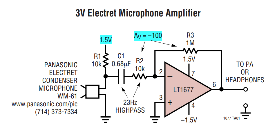
A few reasons, I changed the microphone with amplifier and when measured using oscilloscope and other hardware DAQ, supply range of + 5V and - 5V.
As the MXP is unable to read the voltage-ve, I realized that I need to change the connection to the MSP connector C.
It is mentioned in the dataheet of myRIO we can measure up to differential Channels analog input +/-10 V.
Although there are some reference materials available, I do not understand completely how to read the single ended output using differential input.
Should I use no matter what op-amp or comes directly from their phone?
Can someone kindly explain to me the differences and some references on how to connect!
Although I tried to read through this white paper, I felt completely lost

http://www.NI.com/white-paper/3344/en/
Exit ended unique direct and/or the amplifier has 2 pins: GND and Vout
Entered different a 3-pin: A +, A - and ALWAYS
I had attached the screenshot of the form OP amp for your reference
I think that you just connect your Vout to the + ve differential termination, MASS to Terminal - ve. (Briefly) An asymmetric measure is between the channel of GOT it and STILL while a differential measurement is between the + ve and ve - terminal. One measurement unit completed is referenced to GND is where you are measuring the tension of.
-
Hello
I saw in the specification myRIO manual that it comes with a power cord, but it also comes with an adapter to plug into the wall? Or I have to buy it separately?
Additioanlly, if I turn off the myRIo servo-motors using myRIO to feed servos while the myRIO is connected to a laptop via the USB cable as well as the wall will be the servo motors draw power from the computer or they will draw power from the wall adaptor?
Thank you kindly,
James
Hi James,
1. Yes, both are included.
2. the servo should draw power from the wall.
Make sure that you are in business in the power output of the myRIO specifications when you feed your servo motor.
-
How to install Adaptive Filter Toolkit on myRIO 1900 RT target
Hello
I'm working on the project of Active noise cancellation. I need to collect audio sampling rate of two microphones @40 k and 100 samples per image and audio through speakers @40 sampling rate k of output. For this, I use myRIO 1900 in FPGA high flow personality.
When I'm designing the circuit Adatptive Filter Toolkit pallets are available in block VI, but when I'm trying to compile the circuit I get the error message saying that
"LabVIEW: unable to load the shared library AdaptiveFilters n ensure that the library is present on the target of RT." "Either MAX allows you to install software of OR or FTP to transfer custom RT target libraries.I went to MAX OR to install the Adaptive Filter Toolkit, NI MAX--> network environment--> myRIO 1900--> software--> software add-on
I can't find Adaptive Filter Toolkit or the Digital Filter Design Toolkit.
I seriously doubt the possibility of using Adaptive Filter Toolkit in the FPGA target, but if I create the FPGA VI by default 'personality', Adaptive Filter Toolkit available palettes only not, but if I'm working on the FPGA VI high flow personality, then the pallets Adpative filter Toolkit are available but I can not compile...
So, my question is how to install Adatptive Filter Toolkit on myRIO 1900 RT target?
Is it possible to make custom FTP libraries RT target. I can find the Adaptive Filter library but I don't know which folder should transfer (I tried with several files that I can find but its does not work)?
Please help me
Thank you
If your MAX Configuration looks good.
After this process: NEITHER myRIO 1900--> software--> software add-on
choose user Defined Installation you should get the view like the Picuture I added before.
In find it examples explore, you should be able to get see--> toolkits and Modules--> adaptive filters
Have you already tried to reinstall the Toolkit Digital Filter?
-
Hello comrades,.
I was wondering if there is a way to use myRIO NOR as an autonomous Council with no PC, such as LabVIEW is installed on an operating system and the pogram works on it.
I tried to read about embedded Linux NI real-time OS, but there is no clear documentation of how to use it.
Yes, your LabVIEW project you can create a "time real Executable ' under 'generation specifications' on the target of myRIO that you can deploy on the myRIO and set it runs automatically when myRIO Boote. Obviously, there's going to be any sort of user interface so you'll need to consider how you control / interact with it (or maybe just the log to the file data).
There is a YouTube video that covers the process here: https://www.youtube.com/watch?v=JXoJECRS-eo
There is also a guide here: http://zone.ni.com/reference/en-XX/help/370622K-01/lvrthowto/rt_building_rt_app/
-
Greetings,
I'm looking for a very basic tutorial on the programming of the FPGA on the myRIO.
Most of what I see wrong with retail targeted as your other ' get
started ' tutorials using myRIO. I want to create a digital logic (clock
signals) and/a. function and I need the date and the higher speed than
the RT system offers.An alternative to a tutorial would be a simple program FPGA that starts with
the 'project FPGA Custom myRIO' (' located in the ' LabVIEW myRIO 2013 ' beginning)
screen which generates output a square wave 10 kHz. Once I see how it's done, I think I
can find my way to a solution.Thank you!
FrankThank you nataftw and T - Rex for your time and patience! I started a program from scratch and I launched my first program FPGA. Now to the less difficult stage to build a code for my project!
-
the running program on myRIO with access to controls via wifi
I built balancing robot using myRIO. It does not perform very well and I can control it via wifi. I have now the Setup is simple enough: I can control and set PID and Kalman (accelerometer gyroscope) values. However, there are significant delays associated with the wifi connection. Therefore, if I am happy with my performance robot WiFi (all the controls value) and then I deploy my program on myRIO - changes in performance of robots since the program is run on myRIO now and there is no bottleneck related to sending the data back and forth between computer and myRIO.
To avoid this: is it possible to run the program under myRIO but have a link with all the necessary controls on wifi?
Kind regards
Drakon
Drakon,
Looks like you want to use your computer as a GUI that will read and write variables shared network your myRIO can also connect to.
http://www.NI.com/white-paper/5484/en/
It is quite common to all the treatment more push to a real-time controller while having a user interface on a computer that will basically just reading and writing shared variables. I don't know if this is what you were asking, could you explain what you are currently on your myRIO and your computer, problems you have with your current setup and you want to change?
-
Detect the frequency of an analog signal crossing of myRIo AudioIn analog channels
I'm working on a robot firefighting that runs using myRio. I have a small microphone plugged into the port of "AudioIn' of the myRIO, and the robot has to detect a certain frequency (2.8 or 3.5 KHz) to start navigating. The AnalogIn express VI gives me amplitudes of raw tension of type 'Double' but the 'tone Measurment' vi I wanted to use takes in a data type of "Signal". I tried to convert raw data into dynamic data and feeding it, but did not work. A problem is that I can't control the sampling frequency of the express VI AnalogIn (LabView 2013), I appreciate any suggestions on how to do it.
If you install the myRIO 2014 broadband module you can use the Audio input Express VI to sample between 1 and 30 kHz.
You will need to follow the instructions in the myRIO 2014 LabVIEW Toolkit Readme in the section titled the switching between the default and personalities FPGA high speed.
There is also a thread on the MakerHub of LabVIEW where the Toolbox broadband has been used to generate sound , so it might be a good resource to be part of the path.
If you use NEITHER-DAQ hardware, you can get access to the DAQmx driver but myRIO cannot use the DAQmx driver sample data.
Edit: You can also get more help specific myRIO by moving the post on the discussion forum academic hardware products (ELVIS, myDAQ, myRIO) .
-
I created a VI of for myRIO saved on a USB connected directly to myRIO of data acquisition. However, for some strange reason sometimes myRIO changes USB drive to say designation (sup / v: /) and recently V: / W:. I wonder what would cause myRIO behaves in this way I can prevent that from happening in the future.
Thank you
Assuming you are using myRIO-1900, then Yes, the drive letters an affectante are the myRIO and how it performs this operation is the same described above (see Manual, page 13).
The difference lies in the operating system that runs on the device (RT Linux). The process that goes automatically things is enough nested inside other processes on the device. It's called leg. Research on system folders, check the following locations: /etc/mdev.conf (configuration file), plus, /etc/mdev/automount.sh and /etc/mdev/usb.sh (these files contain the rules for mounting devices)
That being said, you can change the contents of these files to force static drive letters. Unfortunately changing the default behavior is something, that we cannot help you (not recommended), but looking at the good side of things, you can back up files and play with the options, as well, there is a lot of documentation out there to figure things.
I hope this helps
-
How to make the autonomous system?
Hello, I want to make my autonomous system (means do not need a pc to run) using myrio 1900 board.so is necessary to use FPGA of myrio or it can work with programming level RT?
Use of the FPGA depends only on your application.
If your application requires no development of FPGA, you can have only one part RT and create an autonomous system. To create a stand-alone application, you create application RT for your share RT of the software, to run as a startup and deploy on your hardware.
Of course your RT code should not have dependencies on the host, that is, network flow, variable network shared, party etc. Or at least, you must handle errors, related to lost communication.
Thank you
AREV
CTO | RAFA solutions
-
Convert LabVIEW FPGA I16 voltage raw audio data
I use myRIO 1900 and LabVIEW 2015. On the side of myRIO fpga, the Audio IN Terminal gives values of integer (I16) data, while side myRIO RT the real value will come directly.
Of myRIO 1900 user's guide (see pages 7 and 8), the value of the full scale of myRIO Audio IN is of +/-2, 5V. In view of this, my value 32767 should I16 corresponds to + 2, 5V and so on... [ Please refer to this ]
But it's my side RT are does not correspond with the data of the side FPGA data after you have used the above conversion [namely (I16 value * 2.5) / 32767]. I have a dimension value correction factor about 16 i.e. RT = value FPGA converted * 16.
I can't understand this, please explain if someone has expertise in this.Hey,.
for the conversion, please refer to page 10 of the manual named.
The form of the value the ADC has a range of 0 to 4096.
LSB = 5V / 2 ^ 12 = 1.22 mV
Value of RT = value I16 FPGA * LSB


Maybe you are looking for
-
Please delete my account [removed for privacy]
-
OR handset and other relays in the direction of the switch
Hello I am beginner in products OR and now I want to solve a problem. If I know the relay and their connection paths. These relays are of NEITHER and some other producers. Can I Switch Executive put first and last point and automatically will join th
-
E possible print size personalized em has no windows com Officejet 7500?
1. product name: HP Officejet 7500 has 2 Sisetma operational wont: Windows 7 64 bit 3. erro Mensagem: Midia personalozado nao sao allowed without window size 4 Reservoirvolume Freitas no Sistema no antes o problema ocorrer: NAO 5 Assunto: I can not p
-
Vista: Deleted files show no trash
Using Vista will all the updates and Norton Antivirus. When I delete the files, they disappear in the source folder and the Recycle Bin appears complete, but I do not see the files when I open the trash. I noticed that if the trash folder is open b
-
X 220 and an external monitor FHD?
Hello I really like x 220, but also heard that the D - sub port can give a good display quality on large screens, say 1080 p. It is said that the sub - D cannot provide enough bandwidth or something like that. 1366 * 768 being the only option, I'll