Implementation of multiple digital outputs with a box USB-6009
Hi all
I write the code to implement a USB-6009 multiple digital channels, digital outputs independent. I have configured the function of "DAQmx create Channel" to create 'a channel for each line', but I can't understand how to access and control these channels separately. Pointers would be greatly appreciated.
Thank you!
I thought about it. Never mind.
Tags: NI Software
Similar Questions
-
Is it possible to a floating voltage with the output box usb-6009?
Hello
I was wondering if anyone knows how to a difference in voltage output 0 to 1 AO on the box USB-6009 DAQmx AO without reference to the ground. Any help would be greatly appreciated.
Thank you
Bryan
Hello
Page 19 of the manual USB-6009:
http://www.NI.com/PDF/manuals/371303l.PDF
Shows the internal circuits of the DAC are referenced to ground so there is no way to internally isolate it / provide any reference.
Maybe there is another way to make the desired effect? I don't know the details of your request to suggest everything.
Please do not hesitate to ask questions
-
Synchronization of analog and digital output with the external sample clock
Hello
First of all sorry for my English, I will try to explain what I want to do.
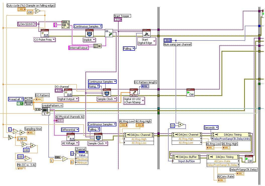
I want my PCIe-6321 to send two custom signals (modification sawtooths) on a mirror controller. I would also like to generate output with my card at the beginning of each tooth of saw. Everything must be synchronized with an external k-clock signal of 100 kHz. The idea is that whenever the PCI receives a trigger to external clock, it sends two analog output voltages and when he received 1024 clock ticks it will also send a pic of triggering TTL. What I do is first prepare the map and after that in a loop sending and modifing the output values of the two signals and at the same time send a digital signal Boolean in each arch, so when's done it 1024 iterations of the loop I send an event to the digital port. Attached you can see.
The problem is that I don't know how to synchronize both. Can I use the sample clock just to the analog output? I can use sample for the two outputs clock, or do I need to use the output of the meter? If don't know how to use it here.
If I do nothing else bad/wrong, I would be grateful for feedback.
Thanks in advance,
PabloI don't know how but I find the solution. I'm generating more than a positive value (as I was triggered maybe very fast the oscilloscope has been absent there). If I put the sample clock of digital output to use the sampling/ao/Dev1 clock that it doesn't, but if I put to use the same source as the OD (terminal where my external clock is connected), but the trigger to start the DO to be Dev1/ao/StartTrigger this works. I don't really know why, but it does.
Thank you for your patience and your help. I put here the final code.
-
Digital output with timer (Simulation)
Hello everyone, I just found out how LabVIEW program a week ago. I try to do a simulation of digital output by LabVIEW (my attachment). In this simulation, I have a slider as an input (0-10 V), two digital controls (upper limit and lower limit), a waveform graph draw these 3 evaluates and two Boolean LED (P0.0 and P0.1) as indicator. In this simulation, you can fill any number (between 0 and 10) in numerical order as a limit for your entry cursor. If the entrance of a cursor exceeds these upper and lower limit, then the Boolean LED lights, P0.0 so exceeds the upper limit, and if P0.1 exceeds the lower limit. The problem is that I do not know how the timer for those Boolean LED. As an example:
(1) make an entry of cursor,
(2) if entry (1) exceeds the upper limit, P0.0 lights for 5 seconds, then turn to during 10 second.
(3) if only 10 seconds, you change the entry back to normal (between high and low limit) then P0.0 will stay turn of until the cursor entry exceeds the upper limit again,.
(4) If, in this second 10 you has not changed the entry (the stay exceeds the upper limit) then P0.0 repeats the process (2) until you the entrance to cursor back to normal.
(Same process for entries exceed the lower limit).
Can you help me do this timer? Thank you

Concerning
Juventom
Hello
If you don t mind I would just give you some advise to your code. To determine the data stream you can also use only the error wire connected to the loop. So Don t you really need, it's beter not not to use variables. For your solution, you can use something similar to what I tried for the upper limit in your program. It is added as an image.
Hope it helps
-
With the help of MAX to configure digital input levels on a USB-6009
Hello
I use a USB-6009 box in a Windows environment. MAX allows me to configure the 8 bits in the port 0 as inputs or outputs. However, when I put the bits for all entries, their default level is high, and the "ALL LOW" button is grayed out. Is there a way I can turn this button to set the bits all low entry and therefore be configured to read a + 5V input pulse?
Concerning
Geoff Hammond
When you set up the pins as inputs, you can read 0 or 5 volts. It makes no sense to set then high or low. No PIN disconnected feel of course a logic 1 because of pull-ups on the device.
-
Control of Stepper Motor with case NI USB-6009
Hi all
I am currently creating a movement control system with a double movement actuator
and two bipolar chopper drives (see table), which should power the motor. We already have a NI USB 6009 in our lab, so I was wondering if I could use it to send signals to the two pilots to control the speed and direction of each axis on the engine?
Enclosed driver's manual indicates that input signals should be 0-5 V DC (TTL logic). I have been informed by the engine distributor that the 0-5 V DC TTL drivers required, the signals are analog. The NI USB-6009 manual reading, there are two 0-5 V analog outputs on the acquisition of data usb so I could provide two signals?
There are often posted however similar problems, it is usually a digital signal NI6009/6009 sends the driver. Looking at the driver's manual, can someone tell if an analogue signals or required as I have said, I was misinformed or 0-5 v DC signal will be enough. I can get more in touch with the dealer if you have any questions you guys think I should ask him.
Thanks in advance for any help! It is much appreciated.
I looked in the manual and it doesn't seem to be very clear. I know that the USB-6009 case is capable of AO and DO, then you would be although it is. I could contact the Haydon Kerk support for more concrete details on the gap between what says the manual and what they told you.
-
With the NI USB-6009 analog input lag
Hello
I try to acquire analog signals with NI USB 6009 using LabVIEW. (The signal is 50 Hz of the functional generator).
However, the acquired singnal has dynamic splitters, which is NOT observed by my oscilloscope.
I have no idea why this phase shift occurs.
Any information is welcome. Thank you for reading.
An image file will not help. Post your real VI. If Firefox does not work, use explore or Chrome to fix your VI (s)!
You have here a Subvi, I don't see what's inside and how it is configured. In addition, this while loop is ridiculous: there is no button to stop him running. Never use the red button to abandon for a normal shutdown of a VI!
Why you have configured NChan NSample? Measure a unique signal, Yes? For example, use 1 channel only.
Edit: why do not you play first with an example given, delivered with LabVIEW?
Your LabVIEW, go to the Help menu--> find--> material and output examples--> DAQmx--> entry--> and open 'Input.VI - constant tension!
This VI allows to enjoy your analog signal.
-
Digital output with NOR-9401 in cDAQ-9174
Hello
I have a cDAQ-9174 with an e/s digital NOR-9401 module. Now I want to output Digital signals on line0:3
$line0: Boolean 1 time = 10ms
Line1: Boolean variable 1 time = 20ms
row2: Boolean variable 1 time = 30ms
line 3:20 pulses (period = 250us, duty ratio = 0.5) after a time = 40ms
the value of line0:3 must be Boolean 0 after 45ms
Can someone let me know what I need to work to solve this please?
Thank you all for your help.
Concerning
Bing
Thank you Christian for your quick replay.
I have some experience in programming of microcontroller with C. I learned LABVIEW for about 1 month and followed a lot of demons in line and tutorials. I know that nodes DAQmx Data Acquisition screws and fundamental property.
As I said at the beginning on the $line0, lin1and line2, they serve to control the relay in my circuit. 10ms could be controlled with the OS clock. Pulse of line3 series is used for IGBT gate signals, which is the critical moment. I want to use the clock machine to accurately control line 3 and synchronize at the same time the pulse with analog inputs from an another two NI9206 modules in the same cDAQ chassis.
I just want to know more on the digital line demand signal relay output and a correlation between the line of analog input-synchronized finished pulse output. Waveform diagram is locked.
Thank you.
Bing
-
Simultaneous analog inputs and one digital output (with NI6221M). Critical moment.
Hello!
Please excuse my bad English.
Idea:
I developed a device to measure the absorbance of light in the sample. The device will have 20 light emitting diodes (led) and 30 light sensitive photodiodes (DP). I have a PCI NI6221M card. As there are a lot of LEDS and PDs the device must use external multiplexing (MUX). The Assembly is shown in figure "DOAI System.JPG". "delta t" figure is not important. It may be zero, one or a few Americans. It is not essential for the operation of the device.
Opreation:
PD 1 will be multiplexed to the AI and the LEDs blinked (turned on and outside), one at a time. Then 2 PD will be multiplexed to the AI and again all LEDS flashing one at a time. The sequence continues with 3 PD, PD 4 and so on. Each blink a led should produce a sample of I. The sampling frequency of the AI should be about 12 kHz (so 80us for example).
Q: It will be possible to obtain from the Commission of NI6221M?
Problem:
I realize that there will be problems. When c generates an address on the MUXs there will be a delay until the LED driver, PD and input amplifier electronics of HAVE it settled. Q: Is it possible to delay the sample clock HAVE some 10 microseconds as to allow that to happen? (Perhaps use an internal counter operating on a basis of time much faster than 12 kHz sampling or use another for me still a feature is not known. May actually leave the sample clock HAVE be the 'master' and instead of delay clock.) Please see the "" calendar of GOT it. "" JPG ".
Q: Is it possible to control the time to settle for AI? That is to say that he can use the 6221, say, 30 US to settle before it reads the value. What these 30 arrive us before or after the flank of sample clock?All reviews are much appreciated,
Markus
Hello!
Just thought I should fill this thread by posting the code that we use now. The moment is as before, but we've added a few nodes property to coacha few parameters. In addition, 6221 has been replaced by a 6259Usb device that allows us to have the best insulation galvanic and more synchronized digital I/o lines.
-
Digital output (0/5volts) using USB or RS232?
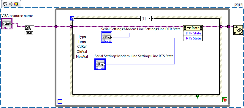
Dear friends, I need to turn on and turn off a device using a few transistors... ect. I would like to turn on/off using USB or RS232 of Labview... I just need to provice was looking for 0 or 5 volts to... Please help me.
Here's a little test vi
Now take a DMM and check the voltage levels on the line DTR and RTS of the COM port you

Should be 9 male pole D sub, careful of not to shortcut some ankles!
measure between pin 5 (GND) and PIN 4 (DTR) or 5 & 7 (RTS)
To light a LED, I would start with a LED of current low and a 10K resistor. If you have the LED's operating
 replace by an optocoupler and resistance in order to limit your current below 5mA. (Say (12V_level - 1.8V_led) / 5mA-> ~ 2.2 kohms)
 -
interaction with chip via usb-6009
I know that the title is somewhat ambiguous. My problem is the following:
I am using an optical mouse as a tool to measure position. I use a chip ADNS-2083 (did not have much luck to find the datasheet, someone else got the chip before you check around the news available.) and I'm following an instruction manual on how to make this project very, only that it uses Arduino and LEGO NXT instead of Labview. I have at my disposal a USB-6009 device, which is connected to the + 5V and GND, SDIO, SCK pins on the controller chip. For the record, I'm using Labview 2009.
Now, the mouse is powered and as such, the LED light up or what - not. However, I don't know how to pass information to the chip via SCK and SDIO. My programming experience is limited, and I never have this type of electronic products.
What I want to know is how to pass 7-bit addresses to SCK and SDIO for control both, and what are the best ways to accomplish this through Labview.
Thanks in advance a ton.
PS: I have attached the pdf file of the manual mentioned above.
cosmicomics,
A quick look at the tutorial that you talk it seems that ICR optical sensor mice using I2C. You will not be able to use the 6009 to I2C communication, instead, you can use the USB-8451, designed precisely for this purpose.
Please let us know if you have any other questions.
Kind regards
Sam K
Technical sales engineer
National Instruments
-
Driving a relay 24V with a USB-6009
Hello
Someone at - it a circuit diagram of how to drive a relay 24VDC with a box USB-6009 and a ULN2803? I've done it before, but I can't find my old tickets and for some reason that I can't get it going now.
I put the chain properly by using the DAQmxBase utility, but I still can't relay to pass.
Any help much appreciated.
Thank you
Got sorted! It was my software not the hardware.
Thanks for the tips anyway.
-
I hope someone can point me in the right direction and also to clarify some concepts!
Background: I am currently using the box USB-6009 and labview on a laptop to output 2 analog waves. It acts as a waveform(0.5-2Hz) of speed (periodic) for an engine step by step (with a driver) to execute a loop of traffic, and the other waveform acts as a signal short 5V to trigger some imaging equipment. The ability to move or to delay the start time of the wave of 'trigger' compared to the waveform of speed in steps of hail (ms) became a requirement for my experiments. Given the time where the USB-6009 case, software based accuracy was not good enough because I need, and the way I wrote the VI limits my delay/travel at the speed of wave deltaT(30-40ms). I started to look at the USB - M series (portability is an obligation) since some have calendar based on the material, and I could send the signal to a buffer rather than iteratively having read every value of the wave in. It also seems that a digital short "pulse" works better than an analog wave form creating any. Where I ran into some confusion is to determine the requirements of a deterministic way sync the two. I am looking for new hardware. I started by looking at the box USB-6211. However, I ran across a few posts talking about the digital I/o correlated being required to perform vaguely similar configurations, which would require something more like the USB-6221. Since I have probably to the digital output to be on a time scale different analog output, is i/o digital correlated required? If not, would the 6211 work?
Just to be clear, I need the periodic waveform and relaxation to be constantly in phase (anywhere, 10 minutes to several hours). Then be able to move the pulse +/-1ms (minimum) and repeat. I can justify the most expensive device if necessary, but I don't want to get something I don't need.
I have attached a figure (not not to scale) of what I am after, in the likely event that my explanation was not too clear.
Thank you
Gabe
Hi Gabe,
The 6211 did not buffer IO digital as some of our other devices. However, there are two complete meters on the 6211 which can be used to perform a generation of pulses (pulse or continuous pulse train - you can output a pulse train using two counters finished). You can take a look at the section Applications of meter output x 621 manual for more information.
What it sounds like, the 6211 will do what you need for the following reasons:
1. the AO of the 6211 lines are buffered and can be clocked up to 250 kHz per channel (in contrast to the 6009 using AO NI by SW).
2 the 6211 counters can be used to generate two pulse based on a basis of time of 80 MHz (12.5 ns pulse width and resolution time). The 6009 does not output meter.
(a) if the two pulses must be on the same line, you must configure a task of generation of pulses finished' (this example uses two meters behind the scenes).
(b) if both impulses are on separate lines, then you can use a task to counter separated for each line with a different initial delay.
The 6211 does not supported clocked generation of digital signals (e.g. 100010101110100) but if you just need to generate impulses so that's precisely what the counters can be used to. I think that's where all the confusion, but seems like the generation of digital signals should not be necessary for your application. Trigger the counter outputs out of the trigger to start AO and adjusting the parameter 'Initial period' should give you what you are looking for. Don't forget to start the tasks of meter in the software before the tasks of the AO (if they are armed and ready to go before the start AO is sent).
I hope this helps, don't forget to post if you have any questions!
Best regards
-
digital output usb6009 does not switch does not correctly
Hello
I have a little problem with my 6009.
Basically, I switch the inputs of a Demux (74HC238D) (3 lines) write an address on it to select rows of data off the Demux.
The signal from the acquisition of data through an FPGA and the signal is displayed on the input pins Demux. That is the problem.
(It is worth noting that the FPGA is well programmed (coz if it was'nt then the signal would not get the demux in the first place.))
When I connect the inputs of the FPGA to 3 digital lines of data acquisition and scroll lines (turning each one WE and OFF), the signal appearing at the Demux pins is not a proper logic level. (the voltage I measured the scope is about. less than 1.1 V). For this reason I choose any line, Demux output will always be on the first channel and will not select the other channel.
I tried the same test 7 connect supply of 5V data acquisition (each line) and after having programmed the FPGA, the correct voltage level is available on the DEMUX pins. The problem occurs when I try to scroll through the entries via the software.
I'm not which is the cause. My belief is the acquisition of data.
What are your suggestions?
Thank you
Labmat
Hi Labmat,
The first thing that jumps out to me is the fact that you use these signals to interface with an FPGA. Outputs digital USB-6009 are 5V or 3.3V TTL and commonly FPGA i/o is 3.3V. Just to double-check, as FPGA did you use?
Q: When I connect the inputs of the FPGA to 3 digital lines of data acquisition and scroll lines (turning each one WE and OFF), the signal appearing at the Demux pins is not a proper logic level. (the voltage I measured the scope is about. less than 1.1 V). I tried the same test 7 connect supply of 5V data acquisition (each line) and after having programmed the FPGA, the correct voltage level is available on the DEMUX pins. The problem occurs when I try to scroll through the entries via the software.
A: This no doubt hits the nail on the head. First of all, I'd be inclined to not use program any software directly and instead use some of the tools for debugging I/O connectivity that come with the Driver NOR-DAQmx. You can get these from the measurement and Automation Explorer (MAX).
' ' ' ' 'Start-up' all programs ' National Instruments ' measurement and automation.
Expand the tree of devices and Interfaces in the left pane, and then select your USB-6009. Using the Test panels button on the right pane, you can quickly perform digital i/o with the device.
Our best bet is to first take a multimeter and see if we can measure the correct voltage is distributed by the correct pins on the USB-6009 case.
Now, by checking the box USB-6009 Datasheet, we can see that, on Page 17, there are a couple of different ways that we can configure the method by which the output signal is driven out of the unit; We have Drive open and active collector mode. It will assure you that since you are trying to send a signal to the FPGA, the unit must be set to active training mode, in order to generate signals from 0V to 3.3V . Output open collector allows the generation of signals from 0V to 5V . This can be done through property OR DAQmx nodes in LabVIEW.
In terms of current...
The + 5V line that you used for the FPGA Nailer is evaluated to 200 my. General DIO lines on the USB-6009 case can generate a current up to 8.5mA. This limitation fits the specifications of digital input of your FPGA?
-
USB-6211 - digital output not supported?
Hi all
I can't use the USB6211 device port... I use daqmx with Delphi7 API functions.
First of all, I tried this:
DAQmxCreateTask('', @TaskDO);
DAQmxCreateDOChan (TaskDO, PChar('Dev1/port0'), ", DAQmx_Val_ChanForAllLines);
DAQmxWriteDigitalU8 (TaskDO, 1, 1, 1, DAQmx_Val_GroupByChannel, $FF, @written, nil);I had an error in the DAQmxWriteDigitalU8:-200012 (= digital output not supported). (???)
OK, I tried to disable autostart option based on DAQmxWriteDigitalU8 and insert a 'manual' start in the code:
DAQmxCreateTask('', @TaskDO);
DAQmxCreateDOChan (TaskDO, PChar('Dev1/port0'), ", DAQmx_Val_ChanForAllLines);
DAQmxStartTask (TaskDO);
DAQmxWriteDigitalU8 (TaskDO, 1, 0, 1, DAQmx_Val_GroupByChannel, $FF, @written, nil);
DAQmxStopTask (TaskDO);Now, I got the same error in DAQmxStartTask:-200012 (Digital Output not supported, once again). (?????)
I don't understand.. 'Digital output not supported "? USB-6211 has 4 lines! What is the problem?
I want to just turn on and off the lines from code...
-Cs George-
Well, finally I figured out...

Here is the solution:
DAQmxCreateTask('', @TaskDO);
DAQmxCreateDOChan (TaskDO, PChar('Dev1/port1'), ", DAQmx_Val_ChanForAllLines);
DAQmxWriteDigitalU8 (TaskDO, 1, @dummy, 1, DAQmx_Val_GroupByChannel, @bitmask, @written, nil);Digital output lines are on port1! Corrected parameter.
And the part of the interface of DAQmxWriteDigitalU8 had to be changed (in nidaqmx.pas).
I don't know why, but the AutoStart (dummy) parameter in the DAQmxWriteDigitalU8 function is ignored: function always starts task automatically, regardless of the value of autostart. But this isn't a problem for me.-Cs George-
Maybe you are looking for
-
Hi eveyone. I go through the motions of scanning photo via web server embedded on safari, the scan occurs and the scanned picture appears in the preview image on the browser tool. So far so good. I right click to download the image to the computer wh
-
Original title: Windows Installer error/problem with shortcut Hello one who reads this. I can't uninstall or remove itunes and quicktime. I was given an iphone today and I wanted to add music. so I connected the phone and waited on itunes to bring up
-
HP Officejet Pro 8620: Wireless HP 8620 browser displays "system error".
After both cartridges are color replaceing, I tried to renew my browser for my HP 8620, 192.168.1.12 but cannot get "System error."
-
No sound on the monitor HP S2331
Have a new monitor and did everything they could to get the sound - even the guys at the shop was rerouted. What I am doing wrong?
-
Windows Update does not work after load Win7 SP1 Ultimate OS fresh 800700E err
Hello This has never happened to me, but I've just loaded Win7 Ultimate SP1 on a laptop, active. I can't get any Wu at all! I do not have the additional languages, I tried the troubleshooter of WU (a few times now), I tried to stop services: msiserve