Implementing an IVI in labview
Hello
I recently created a new IVI driver for a card of NOR-Fgen 5412 max. I'm not sure of the implementation of this driver in labview, however. Can someone point me in the right direction?
Thank you
Eric
If you have configured MAX for the driver AND then use the IVI function generator class driver on the Instrument of e/s palette.
Tags: NI Hardware
Similar Questions
-
Implement pickits.dll in LabVIEW
Hello
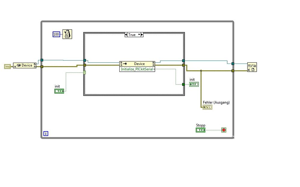
I have problems with the pickits.dll chips. I want to implement the dll file in Labview and communicate with a material called Analyzer series of LIN of microchip.
When I run my Labview VI, it cannot communicate with the device.
It comes to my composition in Labview that does not work.
This composition is created on an OS WIN7/64 bit and a system 32-bit/WIN XP. The two does not work.
The Analyzer is run with the chip Network Analyzer(64bit) demo application.
I downloaded the LIN Serial Analyzer Update v2.05 (64-bit) of the homepage of the electronic chip and with this application, it works.
The pickitS.dll works inside LabView correct. When I run the Prototype of the "Get_PickitS_DLL_Version" function, it returns the correct Version of the DLL.
Is my composition in LabView, right?
Any that work with the Analyzer series of LINEN or similar devices of microchip?
concerning
Hello
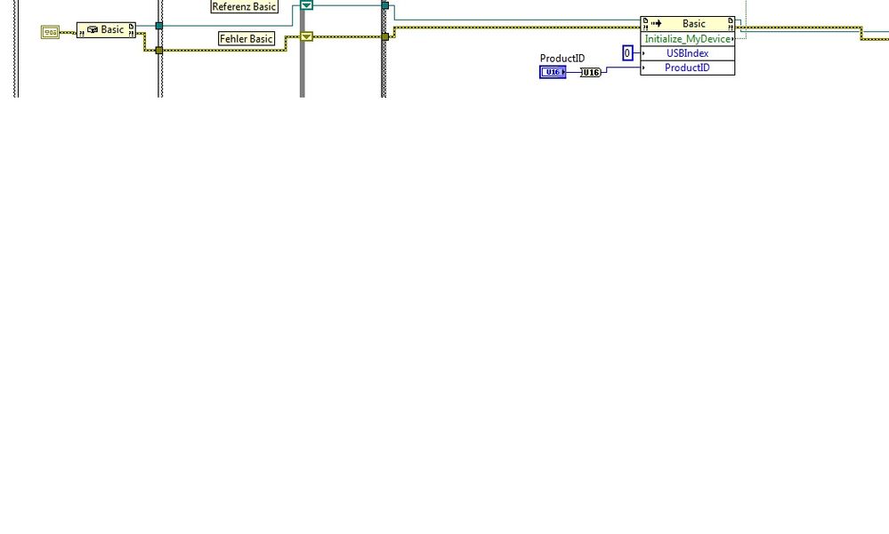
I solved the problem. For initialization of the FLAX series Analyzer, you have to take the ' base' constructor and the 'Initialize_MyDevice' method with the parameters USBIndex = 0 and ProductID = 0xA04. With this basic adjustment, you can initialize the device. Then you must set the baudrate of 19200 for Bus LIN.
Feel free to ask me if you have problems with your device.
-
Need help with implementing DLL based on LabVIEW below call Lib
Here is the list of C functions in the doc that I have, but I don't get the right result.
I need help to understand how these features and how to configure it in LabVIEW
Parameters
voltType
[in] Specifies a voltage detector to get the value of. There may be flags
VCORE (1<>
V25 (1<>
V33 (1<>
V50 (1<>
V120 (1<>
VSB (1<>
VBAT (1<>
VN50 (1<>
VN120 (1<>
ATV (1<>
retval
[out] Points to a variable in which this function returns the voltage in volts.
Typesupport
[out]
If the value is specified as a (non-NULL) pointer to a variable, it will return the types of sensors available in indicators at the level of the ILO-ORed
Return value
TRUE (1) indicates a success; FALSE (0) indicates a failure.
Remarks
Call the function first with a typesupport non-NULL of the sensors available fan and a subsequent call to get the required voltage.Thanks to all...!
I solved this problem.
There was a problem in the configuration of the VoltType. We have a cluster of bits.

-
Implement level translator in Labview
Hello
I need a design of level translator in LabVIEW, such was the level of voltage 1, 8V to 5V vice versa
I'll answer the question that is asked. Attached is a VI that will take an input range which, for the moment, is 0 to 1.8 and it dimensionnera that to a new range which, at present, is 0-5. This could be used with an analog input and output to create what you want analog.
-
Can I implement a stack in LabVIEW?
As a company, I would like to emulate a microcontroller LC3 in LabVIEW. The memory card is like so:

It has a 16-bit word size and is addressable 16 bits. Is this possible?
Of course, it is - use a wide range of U16. In LabVIEW table indices are 32 bit, so you shouldn't have a problem with the 16-bit addresses, treated as an array index.
-
I am not able to install specific drivers IVI in LabVIEW 8.0.1.
The drivers I want to use are for fluke 8846a, 8508a and 5720 a..
The installation of these specific IVI drivers does not have an installation option for the version of labview 8.0, it gives the possibility to install on the versions 7.1, 8.2, 8.5, and 2009.
Help, please.
Hello Christopher,
It is the support for LabVIEW waited for new IVI specific Driver installers (currently released installers only support LV 8.2 and higher). You can simply copy the LV 7.1 on the files to the LV 8.0.1 directories and then mass-compilation live.
See you soon,.
NathanT
-
I am using IVI step switch in TestStand 4.1.1 and also try to call the Actions of LabVIEW using IVI
I use IVI pass the stages and steps of IVI DMM TestStand 4.1.1 and then I have an Action step that IVI spend IVI DMM and features. The problem I have is that if I run the VI in LabVIEW bear only functions without any error, if I run of TestStand without all previous calls to switch IVI or IVI DMM it works also, but if I run the sequence with a step of IVI teststand pass first I get the following error:
Initialize IviSwtch with Options.vi
The primary error: unknown status code (Hex 0xBFFA4001)«"" "String of full appeal:»»"»
Initialize IviSwtch with Options.vi-1074118655; User-defined error code.
I remember there used to be a problem with the steps of the IVI and IVI running LabVIEW, does anyone know if this problem has been corrected?
Other ideas would be appreciated.
Hello Kevin,
It is a question of trying to open more than one session to a particular device of IVI.
Here is a knowledge base on the issue. I found this knowledge base by searching '1074118655' or 'TestStand IVI Action no' to ni.com.
Please let me know if you have any other questions.
-
tables of fixed size in FPGA compilation error - how to implement a waveform control in an FPGA?
Hello
After being stuck for two days, please let me briefly describe my project and the problem:
I want to use the cRIO FPGA for iterative control of waveforms. I want to capture a full period of the waveform, subtracting a reference waveform period and apply control algorithms on this. Subsequently the new period of correction must be sent again for the output module OR. If it does not work, the captured waveform will look like the one reference after several iterations.
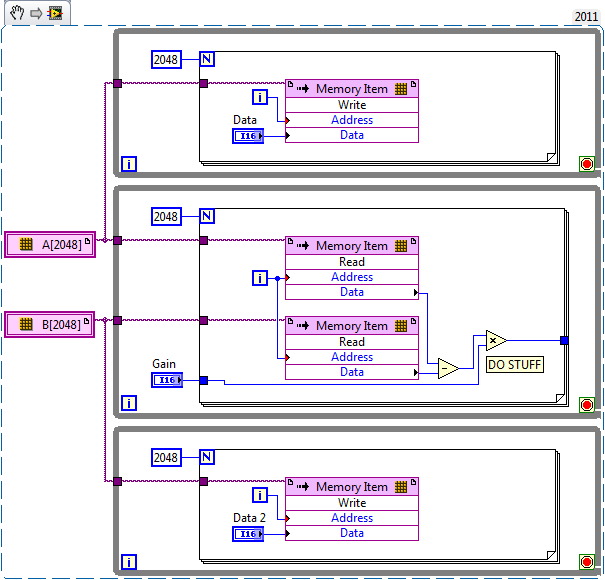
I am planing to create an array of size fixed for the capture and the reference waveform (each around 2,000 items for a given period). I use so 2 paintings of each elements of 2000. I use the function 'replace the subset of table' to update each element captured in the loop sampling and a feedback for each table node to keep in memory (I also tried shift registers, but then the berries do not have a fixed size any more and I can't start the compilation process).
If I try to compile the FPGA vi, I get the following error:
Details:
ERROR ortability:3 - Xilinx this application runs out of memory or met a memory conflict. Use of current memory is 4167696 KB. You can try to increase physical or virtual memory of your system. If you are using a Win32 system, you can increase your application from 2 GB to 3 GB memory using the 3 G switch in your boot.ini file. For more information, please visit Xilinx answer Record #14932. For technical support on this issue, you can open a WebCase with this project attached to http://www.xilinx.com/support.
"Synthesize - XST" process failedBefore I added berries to my code I could compile the FPGA without problems. So, it seems that the tables are too big for the FPGA. :-(
Therefore, I would like to ask if there is perhaps a better method to implement my problem in LabVIEW FPGA? How could avoid the tables to save my waveforms on a period?
Thanks a lot for your help in advance.
Best regards
Andreas
Unfortunately, the LabVIEW FPGA compiler cannot deduct stores shipped from berries (yet). When you create these two large paintings, you are creating essentially several registers very, very large. Just by looking at your picture, I guess that there are at least 4 copies of each of the tables.
You want to use LabVIEW FPGA memories instead. You can create memories outside the loop and then read/write them where you are currently referencing the berries. The only change that you really need to do is to break down your treatment in scalar operations. I have attached a simplified version of your plan, I hope it helps. Let us know if you have any other questions.
-
IVI driver sessions shows no MAX
According to the tutorial of the document "Getting started using National Instruments IVI with LabVIEW or LabWindows/CVI", I have install the sofware IVI Compliance Package2.1, NI VISA5.0 and hp34401a ivi driver, but I can't find any driver in MAX4.7 sessions, it should display "hp34401a" element according to the tutorial document.could you help me? Thank you.
Hello
IVI Compliance Package2.1is an older version of the PIC. Please try to install the latest version of the PIC of drivers and updates, and let us know if you still have any questions.
-
How the resets are generated in LabVIEW for FlexRIO
All,
My background is VHDL and Verilog for FPGA and ASIC implementations. I guess LabVIEW has a point, an only synchronous reset to all of its logic. I create a design that is going to be sections of VHDL IP, through IP integration node is instantiated. When writing to the top of my spec, I need to describe how a reset is spread to all the flops in the design that will be peer-reviewed of accuracy of the results. I need to understand exactly how LabVIEW handles resets to other areas of the clock.
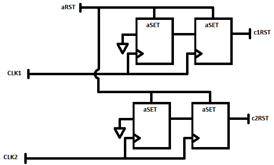
A simple case is the following: I have a 50 MHz external source synchronous data interface and will be a limited treatment of data in this area of 50 MHz using an IP integration node. This IP is designed to have the flops to reset synchronous on the 50 MHz clock.
Separately, I have my most of my treatment and storage to the host (via DMA FIFO) in a field of 100 MHz clock, derived from the clock of 40 MHz I base I must transfer data from 50 MHz to 100 MHz using a FIFO. This treatment at 100 MHz contains a floating-point operations that are reset to zero synchronously to the field of 100 MHz.
In this scenario, you see I have two areas of clock with synchronous resets. I need to understand how LabVIEW FPGA create reset signals which are entries to my integration IP nodes, in order to understand if I need to incorporate any reset synchronization within my VHDL circuits.
Thanks for any help and if you need further details or context, please let me know and I find out additional details.
-Jim
Hey Jim,.
So, option 2 then... in this case, you are looking at a signal of asynchronous reset and must realize in your VHDL similar to the following to ensure that your resets are say synchronously.
-
LabVIEW Modbus TCP with VFD. Could not establish connection / error 56? Any thoughts?
Hello
I'm trying to establish a connection to a VFD (Variable frequency drive) for academic research, for testing purposes. My implementation consists of:
---> LabVIEW (Master)
---> ABB ACS880 VFD (slave) with adapter from Fieldbus FENA-01
---> (ABB motor induction)
---> (Internal Combustion Engine)
First of all, I'm new to Modbus TCP protocol, but I went through all the white papers of NOR, I have read and followed all the instructions from the manual of the VFD and the fieldbus FENA-01 adapter manual. I'm also pretty new to LabVIEW, but I'm confident, I have the knowledge to create the necessary VI.
I created a simple VI who would be able to read some registers the VFD, which is attached below. The VFD is connected by Ethernet to network local ethernet and the Master PC is connected to the same network. When I run the VI, 56 error, which as I read from other messages of the forum is to not get answer within the given time.
I tried the things:
--> Check all cables are connected properly
--> Double check the manuals
--> Checking the FENA-01 in the chassis, which gives the indication of waiting for query modbus
--> Looking for a gateway IP address, but I did not find, so I expected, I don't have to add it to the VFD parameters
--> FENA-01 refreshing settings that always translates to "offline" status
-->, I also checked in Labview > tools > Options where you check TCP/IP and there no port 502 written but I do not change it cause I had to leave the laboratory at the time. The port number was something like 3363 (something like that again)
Issues related to the:
--> Do I need to specify a new device somewhere in LabVIEW or in the control panel?
--> What I need to create a separate VI to make the connection?
--> What 'send 1150 for operating loan' and ' send 1151 for operation "means the control word?
I would be very grateful if someone had information about this before the end of the week. I'm running tight on my period and I just can't stand this VFD with the limited power of the local command of monitoring mode.
Thanks in advance for any help.
Neo
Hello, the problem is solved, and this could be a solution to problems like these.
The IP address of the car was not on the same network as the Local Ethernet network connected to it. The IP address of the disk was 192.168.0.16 and the network was on 192.168.1.1. Once the IP address of the network changed to 192.168.0.1 communicated properly.
I also have ping after and showed the communication.
Thanks for the reply TST.
Peace,
Neo
-
MOU with LabVIEW IR transmitter
Hi, I have built a system in the Arduino that reads the temperature of the meeting room, and when the temperature rises (hot), an IR Transmitter sends a signal to turn on the AC to 17 degrees Celsius, and if it's cold shuts HQ. Then I will try to implement this project in Labview using LINX, I am able to read the temperature and I can turn anything with a condition, but I don't know how to send IR signals in LabVIEW.
To caught up with the IR signal that lights up at HQ, I had to read the signal with an IR receiver, with the help of some codes out there, I found that the signal has been read as:
Encoding: NEC
Code: 38588B 1 (32-bit)...I used an oscilloscope to read the signal, and I got a bunch of bits ' 94 bits'.
000000000000000000111111111010101010101011101110111010101010111010111011101010101110101010111010111011101010101110But I didn't really need it, so my question is how can I send this signal in LabVIEW?
Help! Please, I can share what I have.
As the previous poster said, you do not have a programmatic deterministic control of LabVIEW (pretty much any platform support) - it is expected that there is support of lower level clocked by the material between the level of your application code and the actual hardware, if you try to build deterministic edge transitions or capture pins of entry at a reasonable sampling frequency.
In other environments, support can be DAQmx (or DAQmx Base) and some hardware. Or maybe some hardware third party (such as the previously mentioned RedRat), with calls to a DLL third-party-provided to manage.
My impression of LabVIEW running on an Arduino (which so far is looking over the shoulder of a colleague as he explores), is this native support for LabVIEW for the e/s is VERY limited - I think static port i/o and perhaps than I2C or SPI support. Someone here who is more familiar with Arduino can tell you if you can get LabVIEW to call a support library (as IRLib, the library used by the article you linked to). I'd be surprised if the node to call a library function is supported (yet) on the target of the Arduino.
Dave
-
Reading binary Dump using the DMA (Direct Memory Access)
Hi all
We are trying to measure short-term frequency using the SR620 (frequency meter) via a GPIB-USB connector. We are trying to understand how to work the controls GPIB, and it seems that you normally send a query and then ask him to read what says the instrument. However, as we try to make a measure of frequency stability in the short term, we use the binary Dump command (BDMP - explained in the manual, link below). To read this data, you do not use the standard playback function, you use this process called base (DMA, Direct Memory Access). The maual speaks DMA and the example code in the maual seems to use DMA to read the data that results.
We have been able to trigger the display of "binary output" on the instrument using LabVIEW and interactive control via the NOT-MAX. The question now is: How do we implement DMA by using LabVIEW? More specifically, how we implement DMA reading of the SR620. It doesn't seem to be anything close to it in the code of LabVEIW included. There are examples that use the DMA with IVIs, but we had difficulties to change to work with the SR620 code.
Useful links:
Manual for SR620: http://www.thinksrs.com/downloads/PDFs/Manuals/SR620m.pdf
Possible example DMA? : https://decibel.ni.com/content/docs/DOC-9893
DMA explination: http://zone.ni.com/reference/en-XX/help/371599J-01/lvfpgaconcepts/fpga_dma_how_it_works/
How to make DMA: http://www.ni.com/white-paper/4534/en/
Note: When we did not step 1 passed because we have problems adding a new target of the FPBA, because there is "
". Yes, in ' 89, you probably use a DMA to store the data fast enough. In 25 years, things have become much faster. What I did to somehting similar is to save the data to a file as it is being read. If you want more performance, use a producer/consumer.

-
Hello
I'm working on a project with 3 cameras on a turntable. 2 of them is at the same station and are triggered with a sensor. And the third is at another station, triggered with the second sensor.
The problem is that we cannot control the flow of the game in this table at a constant rate. There are problems of synchronization of image acquisition and to know which picture belongs to which product. To avoid this, we need a model of programming that is capable of storing images, and after this process, the images based on their image number, so we can know images belong to same product. Although I haven't used buffering before, I think that this design can be implemented using queues in Labview.
I couldn't find a way to do this in VBAI. I would like to get images from different cameras and evokes these images based on their chassis and process numbers. Any suggestion would be appreciated.
That's what each picture is for. Once the inspection has loaded and acquire you and process the first image of the camera has, when you get to the stage of acquisition for camera B, even if the camera B has returned 3 images, the step will return the premiera. The other images are buffered by the pilot and the second image is returned on the next call, still more recent images were acquired.
Watch this video that explains better works this way:
http://www.NI.com/Webcast/2872/en/
(Slide 4 - 8).
Try it and let me know if you have any other questions.
Thank you
Brad
-
-Measurement of the pulse width specifies the timeout?
I'm trying to set up a simple project of Signal Express that measure the pulse of two separate signal lines width.
My PCI6224 has two entrances of meter and then run each pulse in the entrance of a meter line, respectively.
The I set up the express project signal attached, which consists of two simultaneously runnings tasks DAQmxAcquire. Each of them is set to measure the pulse for one of the pulse width. I then connect the results for further analysis.
This configuration works very well from time to time. The problem arises when the impulses do not arrive quickly enough and the acquisition of the timeout action. Looks like that has a simple solution - just increase the time-out - but I can't find a single setting around the affects, the time-out! The time-out period is always 10 seconds, regardless of what I do.
Can anyone help?
Thank you.
Hello rothloup,
Unfortunately, there is no option to change the time-out Signal Express for a task entry counter. This has been brought to the attention of our developers.
Reading a DAQmx LabVIEW VI has a time-out node you can specify the time-out period, even in the tasks of meter. I suggest you try to implement your system in LabVIEW (if you can).
Here is a tutorial on how to make PWM in LabVIEW.
http://www.NI.com/Tutorial/2991/en/
See you soon,.
Maybe you are looking for
-
with the help of iTFW for the removal of tracks dead
I prefer to use other software to manage and play my media, but still rely on iTunes for tasks (for example, to manage an iPod). Therefore, I trust iTFW (record shows iTunes) to keep my iTunes updated library... I had not used iTFW for a long time s
-
Satellite Pro 4600 unable to use 128-bit encryption
I have a Satellite Pro 4600 running Windows XP SP1 with the card WiFi PA0307U-1MPC. Installed all the latest drivers listed for the 4600. I can connect to networks using 64-bit encryption, but can not enter the 128-bit encryption. Is it possible to u
-
Tecra S1 - black screen even on external monitor
Hello I'm not sure if this is the right thread for this, but here goes: I have a tecra s1 who was working fine then one day. I turned it on all I get a black screen. I suspect that it's the hard drive but not 100%. I tried to connect to an external m
-
Hello I have a problem with the screen not my A7-50. As seen on the additional screen, the screen goes very dark, except the band and the bottom of the screen. Brightness is maximum. Another possibility of installation menu, that could solve my probl
-
ENVY5530 e-all-in-one:. Problem of the printer (ENVY5530 e-all-in-one) with a sweep
I have a problem I scan a document to an email. The States of "Server connection error" messages and "there was a problem connecting to the server. There is no further explanation or any indication as to what to do to fix. I have never had a pro