improve valve commander during data acquisition
I do acqwuisition dat from 16 channels using NI 6229. the version is labnview 8.2. I want to do vave operation while the acquisition happens. How to implement. Please guide me
Raven
ENGR. ISRO
What acquisition a little you want to do and what should be the result, I responded to another post of yours, are the same two post or is it different?
Tags: NI Software
Similar Questions
-
How to control the sampling time during data acquisition
I managed to manually collect 16 channels of analog signals (writing custom file VI) using a command Boolean start/stop. I would like to allow the user to set a term of the sample on the front panel (for example, 20 seconds) and initiate sampling by clicking a start button. The user can also put an end to the reception of the data before the end of the set time by clicking a stop button. I looked at several examples of countdown timer, but could not figure out how to integrate it with my VI. All suggestions and examples will be very appreciated.
You are far too complicated. On the one hand, there is the function elapsed time on your palette. Secondly, as already mentioned, there is a relationship of basic arithmatic between samples per second and the number of samples to be read. Use you will get samples more than this as requested anyway. Finally, your code shows two analog read tasks. You can do that, unless there are two separate devices.
-
The reading of data acquisition via tcp
Hello
I am building an application that controls an acquisition of data via tcp.
I have a JAVA program that communicate with labview, give a command and data acquisition starts. (So, I read the correct Java data at Labview)
My problem is if I try to read data acquired by data acquisition (continuous sample 1 k samples), I've read strange values.
I transform of double values in the string and send it via tcp.
How can I read it in Java? What type of socket should I use? What is a rate problem?
I also tried to transform small/big-endian byte order, but it does not work.I enclose a sketch of this part of the application.
Please help me, I try for 2 weeks!
Thank you all...I find the solution in the lavag forum.
I post here, if it can help someone.http://lavag.org/topic/16359-sending-LabVIEW-data-via-TCP/page__pid__99983#entry99983
-
We send 5v data acquisition using a voltage generator. Hook us it up to a voltmeter and see 5V. When connect us the generator voltage to a valve "normally open" parker, the voltmeter indicates .14V. It seems that when we connect the two sons of the valve for the voltage generator, the son act as pattern. We want to control the voltage flowing to tap through Labview. We checked the wires to the valve and they work very well, because if we send a constant 5V since the acquisition of data and put ashore, she, the voltmeter indicates 5V. Someone knows why the son act as pattern and low blood to .14V?
nsatpute wrote:
Our data acquisition is NI USB-6259. The valve requires only a 5V max and our DAQ provides up to 5V. However, after connecting the valve to the acquisition of data, the grave tension to almost 0. We start from the principle that the son somehow act as the reason, but we are not sure if this is the case.
The question here is not how much voltage the valve wants, it's the current needs of the valve. The 6259 can put only 5mA via an analog output. Your very likely tap needs much more than that. If you need to add in an amplifier circuit that can supply more current to operate your faucet.
-
Problem of reliability data acquisition PXI-4071
Hello
I'm having a problem of reliability using my 4071 Pxi digitizer mode.
I have a number of tests that use the SMU-6363 (usually configured for DC) analog output to provide a stimulus for our own device, which has a number of a/d converters. We use the PXI system for calibration and testing.
1. I select a voltage ranging from tensions.
2. program the PXI-6363 to drive this tension
3 TIME about 10ms to settle. Note there no discrete capacitors or resistors in the circuit. Everything is parasitic and would generally be under the nF mark and less than 10 ohms
3. configure and Initiate() acquisition of data with the PXI-4071. In general, I use a sample rate of 1000 s/s and get about 30 samples (worth 30 ms). Activation is immediate and I used the default a queue time, 0, set the time and it doesn't seem to make a difference.
4. measure the voltage with the CDA. For debugging purposes I have sometimes made twice once before calling Initiate() and once after. The after is normal. The time required to measure the ADC is shorter than the acquisition time, but regardless of stimulation by the SMU-6363 is constant
5. extract the waveform.
6. the average waveform and compare the value of ADC measured by applying tolerances etc.
Here's the problem: it works well most of the time. But only 0.1% of the time (1 on an acquisition of 1000), I get 8-12 samples that are close to 0. It sounds like a problem of time settling (on the surface), but no matter the amount of wait time data, I always get this behavior. Not only that, but the tension before the call to Initiate() in height CDA, it always confirms that the motor voltage is already set to the programmed value. Nevertheless the acquisition presents near data 0.
So far our independent ADC always reports the expected before and during acquisition (100%) voltage. It's like the DMM input is disconnected during the acquisition during a period of time, because we have confirmed that the voltage is already present prior to the acquisition (component can). I have no errors the insider or FetchWaveForm calls. I still have all my samples. And 99.9% of the time that everything works as expected.
The DMM and ADC are connected to the same point and both are referenced to ground, and as I said before only the parasitic capacitance and resistance (cable). We use a matrix of switching (PXI-2530 (b) to make these connections. We almost always use 51/2 digits and 10V range for data acquisition.
Hello
I thought about it and was going to repost but am distracted.
The device with the ADC also has a mux and switches the mux to an internal node. It only switches when measuring and is open at other times. There is a race condition where the acquisition starts too early and maintains the acquisition after that the switch is open. Unfortunately I don't have the option to trigger.
I forgot the internal mux that I had designed the test years ago and I did some updates to improve the stability of the test. That's why we start the ADC measurement when acquiring.
I just added a routine to reject samples below a threshold
-
Card FPGA and data acquisition synchronization
Hi, we are control and data acquisition of several hardware devices (including Photodetectors and translational stages). Until last week, we used all the controls and acquisition using a PCIe-7852R FPGA board. However, we decided to move the acquisition part to a PCIe 6363 DAQ card to improve the sharpness of the tension. During the test, I found that the internal clocks in the FPGA and the DAQ cards are slightly inconsistent (not just a phase delay, but a difference in the period).
I know because I have generated a square wave (period = 20) using the FPGA and gains using the data acquisition card (at a rate of 200 kHz, that is, 1 taste every 5). I have observed acquired place shifts 5 every 5 seconds approximately. Such a change does not occur if the production and acquisition is done using the same Board. Therefore, the only explanation is that the data acquisition and FPGA cards clock frequencies are different. According to my calculations, the percentage difference between their time clock must be 5/5 s = 0.0001%.
Therefore, I wonder if there is anyway to synchronize clocks between them. Or, is it possible that I can drive the FPGA clock-based DAQ hardware, or vice versa? Also, please let me know if there is something trivial as I fix.
Thank you very much.
Kind regards
Varun
Hi Varun,
my post was only one solution...
Your data acquisition card may take an entry to control sampling of trigger. In this mode, samples draw on a rising edge of the external clock signal. As long as you stay within the limits of the DAQ (100 MHz for your card) material sampling works perfectly. There are even examples coming with LabVIEW explaining how to program your data acquisition card...
This mode use you your FPGA as clock source sampling for data acquisition. Both will run on the FPGA clock in sync. When the FPGA is a bit out of 40 MHz, so it won't matter because both devices are triggered on the same clock signal...
-
TDMS write a comment in the middle of Data Acquisition
Hello
I am currently using TDMS for my data record. Currently I log data from a Keithley module via GPIB connector.
Essentially, I want to save data in intervals and during the recording of data, I want to have a comment section where I can write the changes that have been made.
It connects every minute and I want to add a comment in the minute 5 for example. What is the right way to apply it.
Thank you
I would use a loop that is dedicated to writing in the PDM file. You can then send commands/data to this loop in a queue. You could a single command to write your DAQ data and another for observational data. I would connect all the data data acquisition in a group and observational data in a second group. That will make your file much easier to understand.
-
USBTMC Data Acquisition Device Firmware
Hello
I'm trying to develop a simple data acquisition equipment which can interface with Labview using USBTMC Protocol. The rest of the sheet USBTMC and USBTMC-USB488, I have implemented the code to treat endpoints in bulk-Out with all the message ID. However, I am a little confused on how NI-VISA actually interracts with a device. When a command viWrite or viRead is given, what are the specific messages are sent to the device on which endpoints, and what is the expected response of the device? What would the classic process to acquire large quanties of data from a USBTMC device? If you can clear all this for me, it would be greatly appreciated!
Thank you
Mike
When the host issues viWrite call, the header USBTMC_BULKOUT of 12 bytes followed by your channel SCPI is sent to the endpoint of your firmware BULKOUT. In this case, USBTMC_BULKOUT header contains MsgID = 1.
When the host issues appeal of viRead, USBTMC_BULKOUT of 12-byte header must be sent to ask for playback to the BULKOUT endpoint. In this case the MsgID = 2 and the length is only 12 bytes of all. Then your firmware, if a response string is ready, must set the header USBTMC_BULKIN followed by the answer of the SCPI endpoint to send BOULKIN.
viWrite generates a transaction BULKOUT and viRead generates a transaction BULKOUT more BOULKIN transaction.
example:
viWrite ("* IDN?") \n') - generates a transaction bulkout in the form of bytes [12 + 6 + 2]. (the last 2 bytes are padding to align the 4 bytes)
Correcponding viRead () - generates a bulkout in the form of bytes [12], then the firmware fixed Boulkin data [12 + response + padding].
Makoto
-
How to increase the speed of data acquisition?
Hey, currently I using 6210 OR of data acquisition and control switch. I used labview to periodically check the 7 switches and read data from 7 channels in the meantime (1 sample on request). I ran 70 loops for 10 groups of data, the cost of the time looked like 2.2 seconds.
I would like to end a 700 loops in 2 seconds, is it possible to improve?
Thank you
PEM
Look at the Terminal stop of the DAQ Assistant Express VI. You are starting and stopping of the task for the acquisition of data on each iteration of the loop.
Starting from the help file:
Stop
Specifies to stop the task and release device resources when this Express VI ends execution. For ongoing tasks, this entry is FALSE by default, which means that the task is running until the application terminates. To stop the task, you can use the device again in the same application, wire control wire you the Conditional stop this entry to the same terminal of the while loop. For single-point and finished tasks, this entry is TRUE by default, which means work stoppages after all samples are acquired. To optimize the performance of single point when using this Express VI into a loop, wire control wire you the Conditional stop this entry to the same terminal of the while loop.
Also from the help file:
Continuous single point of entry or exit, the of VI Express DAQ Assistant cannot allow optimal operation. See Acq & chart voltage-Single Point optimization VI in examples\DAQmx\Analog In\Measure Voltage.llb for an example of techniques to create more powerful applications, single point of I/O.
-
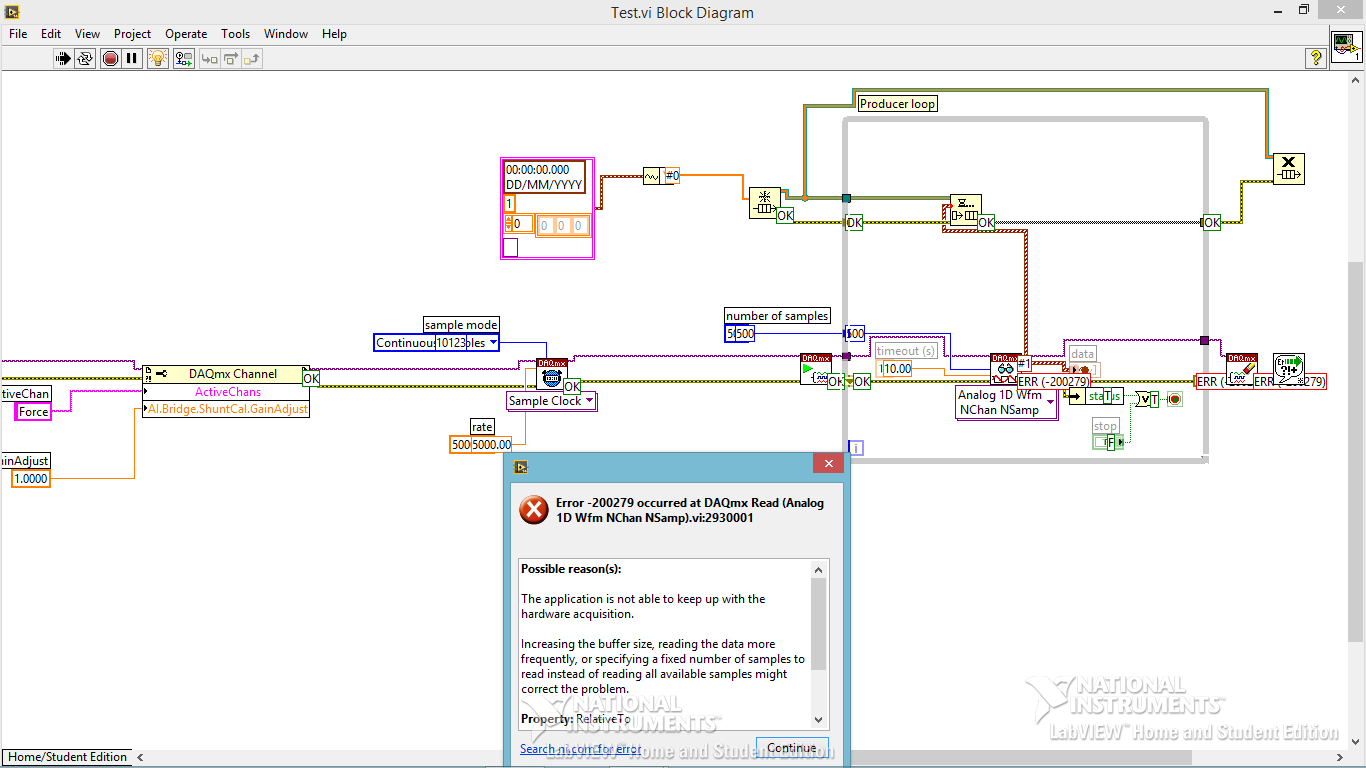
Code error-200279 for data acquisition
Hi all
I am trying to build a small program of data acquisition, but I get a 200279 error telling me to increase the buffertime. What I am doing wrong?
Andersson wrote:
No, you're right. I don't get the error, I turn off highlight execution.
It seems so. I did not understand why he would come with an error during the audit of the code with the bulb. It seems like what I discovered on www.ni, one can avoid the error of initialization of certain data for the chart.
Not sure if I got it 100% correct however. Here is the link:
http://digital.NI.com/public.nsf/allkb/A647A1BE3DA8336786257AAA0066B45B
I don't have any other loop in the installer. I'm sorry for the confusion with the name 'producer loop. It's the only loop in the code, I deleted the rest to refine the error.
Is the conclusion that the program is good? Or do I have to do something to remove the error?
The table has nothing to do with your error. It's strictly highlight execution.
When you configure a continuous sampling, start the collection of data at a given flow rate. It is so big a configuration of the buffer. There is an article that tells how much room it is exactly, but for the sake of argument, let's say 10 seconds worth of data. In normal execution, your code runs pretty quickly that she is able to empty the buffer as soon as the data are acquired. But when you enable execution of climax, your VI slows down to a crawl so that he can show that you step by step what is happening on each wire. Your data acquisition always occurs in the background. Execution of idle is to take much longer that data are acquired. Within one or more loop iterations, you have filled the buffer and get the error message.
You cannot use point culminating performance when you use a device of data acquisition in this way (or VISA ports either) where data are sent continuously at a speed that is independent of speed, the code is executed.
-
digital triggering of stop/start of analog data acquisition
I want to use a signal from a digital line to start and stop analog data acquisition. The signal can change levels several times during a race of the VI so I have to start and stop several times data acquisition and store each session data in a different file.
I tried to play with the following screw: digital triggering of break, DigitalStartandStopTrigger and ContAcq_DigTrig. None of them doesn't seem to work for my configuration. I also do continuous data acquisition so I can't use a reference. I use PCI 6259 DAQ.
I used the "P0" pins rather than PFI pin on the grid BNC-2090. I know... stupid enough.
-
Executable doesn't detect data acquisition
Hello LabVIEW community,
I created an executable file to run on a computer that has no LabVIEW. I installed the hardware drivers on this computer (my DAQ hardware is "installed and ready to use" and detected by the computer on the plug-in). The problem is that when I run the file .exe, all my channels DAQ read just 0. The code behaves as if data acquisition is not connected or is not recognized.
I tried the same executable on the computer where the .exe is created, and the signals are well displayed.
Is there something special that needs to be made during the creation of executables, to ensure data acquisition channels are detected on all computers? It is perhaps a matter of configuration by computer?
Thank you in advance for your help!
If you use DAQmx tasks or channels defined in MAX, then you must export your configuration of MAX to the target computer as well. Your Installer can be put in place to manage the import of MAX settings during installation on the target computer.
You should also follow the advice of crows and make sure that you implement the error handling.
-
not able to write the data through data acquisition
Hello
In fact, I need to send a code word (text file) from the program matlab through my data acquisition (OR-USB-6215). my program (transmitter.vi [case structure: page2]) attached below has a problem to do the task. whenever I run the program it gives me an error like
Error-200479 occurred at DAQmx start Task.vi:2
Possible reasons:
Measurements: Specified Operation cannot be performed during execution of the task.
Task name: _unnamedTask<84>
At the moment I don't see output in my oscilloscope. But, if I highlight my performance I observe my samples on the oscilloscope with the following error message
200288 error has occurred in the DAQmx write (analog 1-d 1Chan NSamp DBL) .vi:3
Possible reasons:Measurements: Attempted to write a sample beyond the final sample generated. The build is stopped, so the sample specified by the combination of the position and the offset is never available.
Hi Raja,
What I did is I moved the 'write DAQmx' outside the while loop. That made the VI in this case is read the file and passing it to a table, and then this table is formatted a waveform to be written to the data acquisition device.
With respect to the way in which the data is read, I don't change anything, it was based on your original code. A good way to know if you write the correct data is to check the chart view in VI.
So the question is, is the graphic display showing the good waveform?
Best regards
Faris
-
choice of the model of design for data acquisition system
Hi all
I have a problem on the selection of the model design / architecture for a data acquisition system.
Here are the details of the desired system:
There are data acquisition hardware and I need to use by looking at the settings on the user interface.
the period of data acquisition, channel list to analyze must be selected on the user interface. In addition, there are many interactions with the user interface. for example if the user selects a channel to add scanlist, I need to activate and make it visible to others on the user interface.
When the user completes the channel selection, then he will press the button to start the data acquisition. Then, I also need to show the values scanned on a graph in real time and save them in a txt file.
I know that I can not use producer consumer model here. because the data acquisition loop should wait for the settings to scan channels. and it works on a given period by the user. If the loop of user interface makes higher then loop (loop data acquisition) of consumption. This means that queue will be bigger, larger. If I use notifier this will be some data loss comes from the user interface.
y at - it an idea about it? is there any model of design suitable for this case?
Thanks in advance
Best regards
Veli BAYAR
Software for embedded systems and hardware engineer
Veli,
I recommend the model producer/consumer with some modifications.
You might need three loops. I can't tell for sure from your brief description.
The loop of the User Interface responds to the user for configuration entries and start/stop of acquisition. The parameters and commands are passed to the Data Acquisition loop via a queue. In this loop is a machine States that slowed, Configuration, Acquisition and stop States (and perhaps others). The data is sent to the processing loop through another line. The processing loop performs any data processing, displays the data from the user, and records to file. A registrant can be used to send the Stop command or stop the loop of the UI for other loops. If the amount of treatment is minimal and the time of writing files are not too long, the functions of processing loop might be able to happen in the case of the UI loop timeout structure of the event. This makes things a little easier, but is not as flexible when changes need to be made.
I'm not sure that there is a type of design for this exact configuration, but it is essentially a combination of the models Design of producer/consumer (data) and producer/consumer (events).
Lynn
-
Missing PCI Data Acquisition and Signal Processing controller drivers
Hello!
I have a problem with my Inspiron 11 3148
Service etiquette: CSFND32A few weeks ago, I did a clean reinstall of windows 8.1 using a .iso downloaded from microsoft technical support and put in level to windows 10 in a short time after.
I don't have my thumb drive installation, where the microsoft .iso image file.
Since then do a clean install, I had a few questions I'm going to break my best.
1. lack of drivers for unknown devices & a PCI data acquisition and signal processing controller.
I had some problems with wifi, so I looked in the Device Manager to check if my card needed a driver update and discovered several other device driver errors, which cannot be resolved by using windows update. The card wifi itself says it is updated.

I tried to use the dell service detect downloaded applet on the page of the Dell driver IE, but it does not seem to function.
If someone can identify what (s) I might need for these unknowns that would be fantastic.
2. Wifi issues, perhaps in connection with the missing drivers above.
-Sometimes does not detect networks.
-Sometimes cannot connect to the internet when it is on my home network.
-Is not able to connect to weak points where before he could.
* Reset the network adapter in the network settings fixes detection and connectivity issues, but does not improve the detection of signals in weak points *.
3. high (100-96%) HARD drive load for a few minutes after start high and very occasional errors "in areas not paginated page failure."
-J' lived load disc high enough the last time I got the upgrade of 10 windows the first time, requiring often 5-10 minutes to settle at startup
-Second time around, I always get high disk load, but it is not too long. The upgrade fee is very 'light', I have very few programs installed and even less to launch at startup.
-Defects of Page seemed generally coincide with me shortly after you start using Google Chrome. I now use firefox instead and have known only one mistake so far since the permutation
* I used the windows disk check and ran chkdsk /r for longer check disk to reboot, but both are no problem with the drive *.
Ok... So usually after I finished writing this post, I came across a solution for the number one problem while browsing the microsoft answers forums.
I downloaded and installed a driver for the Intel platform dynamic and thermal framework.
-This solved my problems of missing driver.
-J' rebooted several times and I am not also problems of wifi the day other than the problem of low task, but what I'll take it!

Maybe you are looking for
-
Apple Watch - emails will not erase, Archive
My Apple Watch will let me "delete e-mails. It only gives me the option «archive» I put in place on the Apple Watch App on my iPhone for 'mirror' watch my email on my phone settings, I got to "delete e-mails" rather that "archive". Yet on my Apple
-
I received the automatic update of windows Vista and another program and tried to update and receive error code 80071AA7. I could not find data on this code on microsoft. Thoughts, or ideas what this code means?
-
I get a Mode not Optimum / recommended Mode 1920 x 1200 on my game and he's not coming how to get down off the coast?
-
installation of the configuration of the hp photosmart camera for windows 8
HP Photosmart 5515 Windows 8 Cannot install printing software Installation/setup disk are not run on Windows 8 (suggestion: any software compatible with HP printer Photosmart 5515/Windows 8?) Thank you!
-
Desktop on a Dell Latitude D510 problems
Hi people out there. I'm on a Dell Latitude D510. Since 2 days back, I can hardly read what is on my screen and have resorted to connect a desktop monitor. I can make very very weakly, what is on my Dell screen, but the resolution is so bad I'm stuck