In differential Mode input impedance
Hi all
When I bought the USB-6212 card, I was impressed by the high input impedance of it - 10 GOhm.
This is indicated in the specifications, as in between HAVE + and AIGND.
So, what is the input under differential connection impedance?
Hi Navneet,
The question you have posted is actually a matter of multifunction data acquisition. You should post these questions in the Forums Multifunction DAQ. You will get much more quick answers to questions that are displayed in the correct forums.
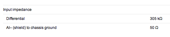
The input impedance, in differential mode is a little less, then twice the impedance of the AI referenced to ground. What this means, is that he will be GOhms ~ 20 to 19. The actual value is not available, because it's such a high input impedance.
Best regards
Jonathan
Tags: NI Hardware
Similar Questions
-
Problem: The differential mode, measure 1.4 V, USB-6009
Hello world
I am able to charge and discharge the two capacitors, individually.
I use the USB-6009;
Two capacitors, two charts, two analog inputs (AI0 +, AI01-) and (Al1 +, Ai1-);
I have configuredin differential mode; Ok
Problem:
When a capacitor is switched off, it measures 1.4 V
Try to correctly set the task - run the DAQ Assistant to create the task

Dev1/ao0 would be much better - Oh, and now that you take the wizard open-Do on the wiring diagram, it offers you

For the PREMIUM of 6009 task mode AI0 is + AI3 is - and you only reserve reserve explicitly AI0 (AI3 line is reserved by seleting the + line in the channel and the declairing it is differentiated)
And give the task/channel a significant name of "MyCap1Discharge" would be useful...
Now let's talk about your electrical engineering:
The input of the 6009 impedance is 144kOhms the resistance of discharge 1MOhm becomes useless as soon as you connect the control AI 6009.
-
What is the input for NI9234 input impedance and where can I find it in the sheets in general?
If you scroll about 3/4 of the way through the online data sheet you will find this:
The differential input impedance is also the tab specifications of the NI 9234 product on the web site page of NOR.
Lynn
-
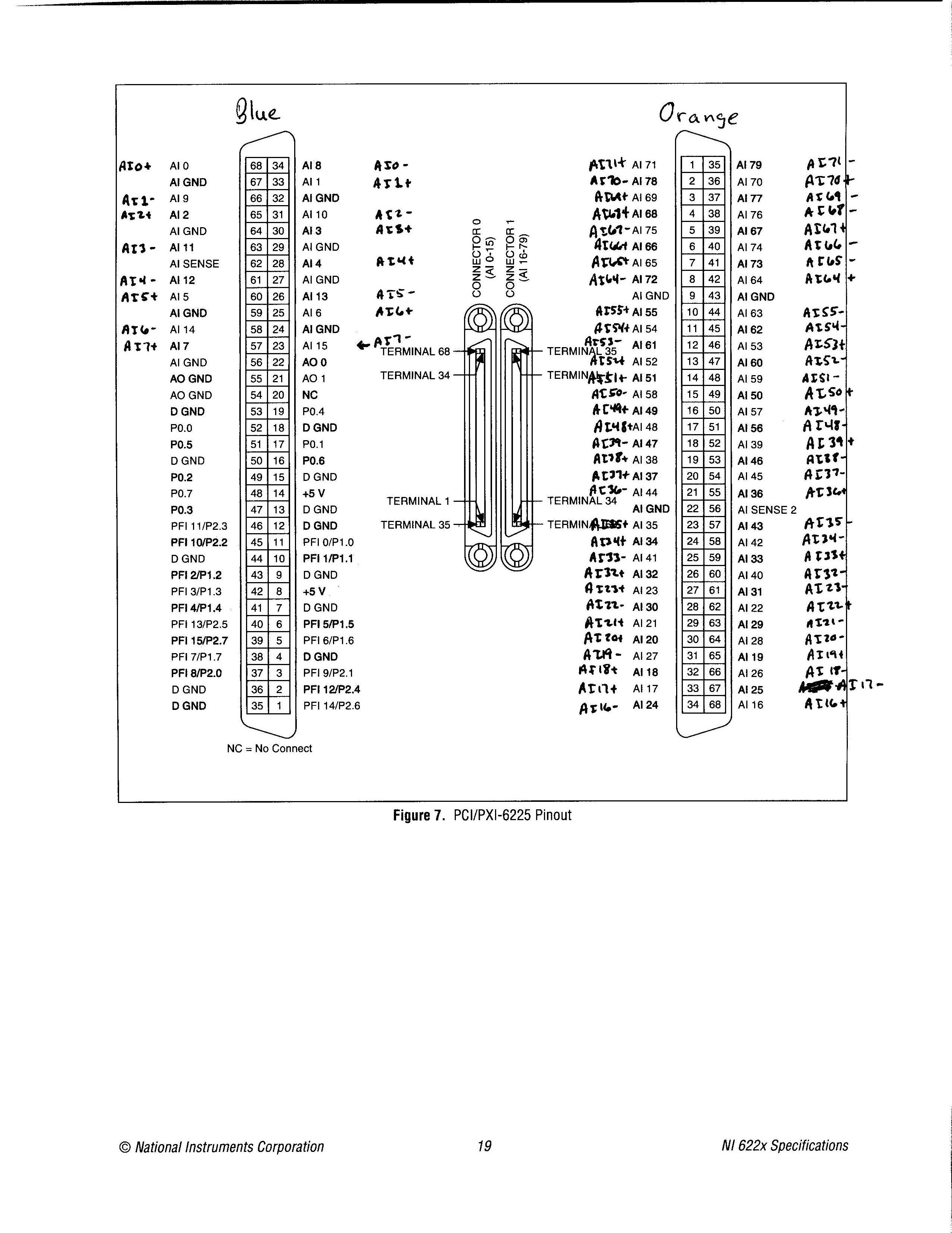
Pinout of the device from the PCI-6225 in differential Mode of I
Simple question: where is the pinout of the device for the card PCI-6225 for differential of analog input mode? I looked in the device list of the pins in MAX, in the NI 622 x specifications document and several other places, but I was not able to find it. I found the pinout for referenced asymmetrical measures, but no differential.
Related issue: most people use devices like the 6225 for no entries analog differential? So why in tarnation do many brand of material OR that upper and lower manuals, looking for the differential input version?
Thank you!
«Referring the number of pins would make it impossible to use the same code when you change maps DAQ.»
I'm not sure I followed here. Can you please explain a little further? Are you referring to the 1-68 0 connector pins and 1-68 pin connector 1? If so, I'm not sure, I followed. A different pinout may not change the code. If I had to replace a 6225 with another equivalent at least DAQmx device as many channels and the device number was the same, then I'd not change all the names of channel in the code, I? It would certainly change the wiring, which is precisely what I'm doing right now.
I know that the analog input channels look like ai0, ai1, etc.. My concern is later: where the jumps occur when you're in differential mode?
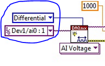
I have attached exactly what I would like to see in the documentation of ALL analog input device which allows the differential mode, only with the + and - channel names only and not the labels AI0-AI79. I couldn't find this photo any place, but rather had to laboriously calculate this pinout. If you know where to find this photo, I would be very grateful.
Thanks for the reply.
-
Unusual in differential Mode: Urgent
Forum from hell,
I have a situation where I can't use the connections of CSR considerations of noise. So using my USB-6212 I enclose 8 of my sensors in differential mode with return line common to all HAVE them (-) 8 inputs and a reference sensor. I use the resistance of polarization of 100 kohm on all lines HAVE (+) and I (-) all lines. Is this correct? I mean since the lines HAVE (-) are common to all, should I connect only 100 kOhm?
I think since I connected 8 resistances of polarization on a common line shared by all HAVE them (-), which effectively reduces polarization resistance at great value lesse (parallel connection).
Please advice

see you soon,
Navneet,
If the lines of AI are all connected to the same node on your measurement, so yes you can use only a single polarization resistance.
Kind regards
Danny F
-
[visual studio c++] on the input impedance
If you look at the manual and specifications, this device supports only 1 M ohm input impedance.
-
Hello
I am trying to acquire an output of my DUT using the 6552 map, and the 6552 50 ohms default channel input impedance. It's pulling down of my output, so I want to change the impedance of 10K or 50K entry but I can't seem to do.
When I run the example of the input channel Impedance.vi and change to the 10K or 50K input impedance, it remains to 50 ohms. Similarly when I add the relevant property node (to change the input impedance) to my vi, remains at 50 ohms. I use the channel 0 as my string of acquisition and channels 1 to 7 as my production lines.
Any ideas?
Kind regards
Barry
Hey, Barry!
Can you post your code? Also, what version of NOR-HSDIO do you use?
Thank you
Keith Shapiro
National Instruments R & D
-
NI USB - 6212 BNC analog input impedance matching
I just ordered a case NOR USB - 6212 BNC DAQ (should be delivered soon). I want to use to measure HV signals using a probe of high voltage of 1/1000 I have.
Now, datasheet of the probe (not a lot of info) says it has an impedance imput 100MOhm. I suppose that it consists of a simple resisitve divider, and if the ratio is 1/1000, I wait so to have a 99.9MOhm resistance in series with a 0.1MOhm resistance. However, the data sheet also specify that the probe is designed to be connected to an oscilloscope with an impedance of 1MOhm. As this input impedance is very low compared to the low value of the separator of resistance resistance, so I guess that the real resistance at the level of the sensor values 99.9MOhm and 0.11MOhm (to obtain the 0.99 and 0.1MOhm when it is connected to the oscilloscope for 1mW).
Therefore, given that the impedance of the USB-6212 according to the datasheet, the analog input is > 10GOhm, I expect to measure higher to true alternative voltages when connected to the acquisition of data from 10%. This assumption has a meaning?
What would be the best way to get around this? Do a calibration and correct the values acquired in LabVIEW code? Or should I add precision 1MOhm resistance at the same time to the acquisition of input data to decrease its resistance to entry to the value expected by the probe?
Thanks for your help!
Since you have a range of 1000: 1 I guess you also need bandwidth (I have a TEK 6015 A
), so you need based on the impedance input, a complex value, means he must not only watch but also the ability to input resistance (1 M). demarcation of the field probes have usually some elements of toppings to match the probe and the input scope. RTFM of the help of the probeBUT a more serious point is that with your probe, you have a very high resistance. And if you look in the specification of the 6212 you will find on page 2 by mistake ppm in logarithmic scale graph! and even 100 k source impedance it not shown.
So I'm afraid that a simple 1 M on the DAQ entry can work if you're only measuring DC, and only if you use a channel on the acquisition of data. A workaround is an amplifier separate buffer with an impedance of good entry corresponding to the specification of your probe and a low output impedance.
-
Read a bit off in differential mode in NI 9205
I have an LVDT connected in differential mode in NI 9205 tends in NOR cDAQ 9172. The output signal full scale is from-10 to + 10 VDC VDC. The excitation voltage is +-15VDC. I placed the LVDT to read mVDC - 1400 on the digital multimeter (DMM), well, it oscillates between 1399 mVDC and mVDC-1400. When I read that in Labview 8.5, reading is about-1.410 VDC, oscillates between - 1.407 VDC and - 1.414 VDC. I know an offset of 10 mVDC isn't that much when my output full scale is 09:50 VDC and I'm not losing my sleep on. But I just wanted to know if it was normal.
The output LVDT signal is referenced (-terminal of excitement and - terminal of the output signal are linked, it is necessary) and I plugged this thread of land on the port COM of NI 9205.
I also have a sensor with floating floor whose output is 0-100 mVDC. I have it connected in differential mode too the + and - output terminals are connected to the ground/COM port using 100 k ohm bias registers. In this case, it is without lag at all. The DMM and Labview show the same reading. By the way I am at the same time by displaying the readings in Labview and DMM.
Hi sharmaa -.
You can find your shift error using pages 23 and 24 of the NI 9205 manual Instructions and specifications. 10 mV seems a bit high for this particular card, but as you say, 0.1% isn't so bad. I would say that you have the right not to lose sleep on.
Have a great weekend!
-
question about the input impedance
Hello world
I tried to measure a voltage with internal impedance 10kohm source, and I connect to the source directly with the NI USB 6009. When the voltage source is 5.043V, the data recorded by labview are about 4.8V. I checked the manual of the USB-6009 case and found that the input circuit (see attachment). So I guess when the device was taken from data, it actually takes the data on the node of crossing and converted, then return with impedance numbers shown in the graph. That's why I'm given to me below that it should have been.
I was wondering is it possible to treat it, other than the calculation of return and convert it with correct impedance?
Kind regards
Jude
Hi Jude,.
you could use an op amp to boost your signal (1:1), one so reduce the impedance seen by the USB6009. You can also use some other DAQ hardware with a higher input impedance.
In the end, the conclusion is: you must choose your DAQ hardware according to the specifications of the signal source. You have selected the wrong hardware...
-
Example of Code OR-DAQmx (C/C++) for playback of 8 differential analog inputs on USB-6215?
Are there examples using the API C/C++ of NOR-DAQmx in an application that illustrates how to read all 8 analog channels (differential) on a device USB-6215 or similar? I can find examples to read only one channel, but nothing for multiple channels. When I try to read all 8 channels, I get only entry on the first channel. Any help would be appreciated.
Kind regards
Bob
Brandon:
Thanks for the tips. I have it working now.
Kind regards
Bob
-
Using a FP-I-V5 in differential mode
Hello
I'm creating an application by using the Modules of Point field. I use some memory twin for i/o modules. Does anyone know how we should connect module FP-I-V5 channel as differential. Examples of the operating instructions do not cover the case of differential.
Any help would be appreciated.
Hello
Dual Channel FieldPoint modules are isolated from each other. For analog modules, such as the FP HAVE V5, the two channels on the module share the same commune, while they are considered to be asymmetric. However, if you only use one channel, you don't share in common with the other channels and are therefore the differential measure.
To use the FP-I-V5 as a differential module, simply use a single channel.
Kind regards
Green shores
Support Engineer produces FieldPoint
National Instruments -
PCI 6221 analog input impedance?
Hello
I have a card PCI-6221, I know the impedance of an analogic imput?
Thank you.
Hello
As shown here, when the device is turned on, more than 10GOhm in parallel with 100pF
-
How to set the differential input for personal iotech Daq/3000 mode
Hi all
I currently use personal iotech daq/3000 for the acquisition of data from the accelerometer.
I got readings of the analog input, while there seems to be no configuration for the differential mode.
What I have is:
selection of material - personaldaq / 3000:direct
Double click on, then:
Channel installation, there should be a selection of differential mode, I guess. But this is not.
Thank you very much
Alan
Have you reviewed the C:\Program Files\DASYLab 10.0\manuals\IOtech_DAQ_notes. PDF? Or the help of equipment?
The section of material assistance, using the analog inputs with DASYLab, includes pictures to show how to do this.
Open hardware driver.
Click the line Analog Input Channels, and then right-click to open the properties. This will display a dialog box that allows you to set the properties.
-
What is the analog input of the NI PCI-6229 impedance?
I am trying to determine the effect of a 12 K resistor that is in series with an analog input of an NI PCI-6229 data acquisition card. Resistance of 12K seems to be part of a RC filter. I have a 0-10 VDC source this supply circuit. What is the impedance of the analog input of the NI PCI-6229 data acquisition card? If it makes any difference, the analog input is connected in differential mode with a 180K resistor to Gnd AI.
Thank you
RWB
Hi, RWB,.
The input impedance is classified in the specifications 10 GOhm. So, the effect of your k 12 resistance should be relatively low. Take care!
Maybe you are looking for
-
Why I can't to the previous page by pressing the back only one button only once?
Hi it. My problem is when I try to go back to the page previous (s) and hit the back button nothing happens. I have to hit twice or three times to force the action. What happens after the last update of mozilla. I know that in previous versions of mo
-
See the sentence
-
BT stack hungs TosBTMng.Exe file during shutdown
Hello I'm running a FSC-Notebook that came with the BT-stack from Toshiba. The laptop is in W - XP, SP2, MCE, updated with patches of M$. I installed the 5.10.12 BT-stack. Shut Down the PC stops with a window that does not have TosBTMng.exe. (not rea
-
should what program I open documents pspimage
-
Do not update Windows (error code 8007005)
Windows do not update. I get the error code 8007005. Eventually Windows is damaged? I have recently reinstalled Windows 7 upgrade (from Vista) when I did it I got an error (no real product Windows) but it is, and product code has been accepted. This