Incremental Quadrature encoder
Hello
I use an encoder incremental quadrature.
I ran the position.vi of angular measure in the examples to find > measure angular position.vi
However, I always get the angle between within 360 degrees.
How to obtain the more than 360 degrees (i.e. If the tree goes more than a tour)? I don't want to see after 360 degrees, then it return to 0 degrees. 1 degree etc.
Can someone change the position.vi of angular measure to accommodate the jumps from 360 to 0?
Thank you.
You have the encoder in front of you? Give it a try. Spend some time to learn about the counters and encoders.
You will get no help from me until you demonstrate that you are ready to follow a proper forum etiquette. Don't send personal messages. Two months ago you sent me a personal message and I explained to him that you should rather post on the forum. Yet you did exactly the same thing again today. If I had noticed that you sent me a personal message before posting the same question in the forum, I would not respond at all. Then, when you do not have an immediate response later in the thread, you followed up with another personal message containing exactly the same content. This is not the right way to get help here.
Tags: NI Software
Similar Questions
-
VI quadrature encoder does not work after programming of FPGA
I'm rather new on the MyRIO, and I work on the motor of the MyRIO and read control in a quadrature encoder at the same time. Programmed individually, the two pieces of work at Marvel, but once I have combine them and try programming, control of motors not to not work signals, but the reader encoder does not work. I use the Express VI for the LabVIEW quadrature encoder reader, and I produce four stepper motors signals using FPGA.
It seems as if the encoder is disabled when I program the FPGA with my code, because if I have two parallel loops, one for the reader encoder and the control of step motors, if I stop the loop of step motors, the encoder works immediately.
Is there something simple that I'm missing? Any suggestions would be greatly appreciated!
Thank you
Enan
I realize now that my last answer could have been confused and not useful to someone else who may come across the same problems later.
Here is how I solved the problem I've had:
I had to derive Boolean expressions for an encoder quadrature (essentially to create my own) and then used the outputs (UP, DOWN) to increment/decrement a counter using the conditional statements. Then, I stored the value of direction in a flip flop implemented using two conditional statements of T/F in series and connected to a shift on the edge of the loop register.
It was all able to be implemented in a single cycle timed Loop, and then I managed to place in the same loop that I used to control stepper motor.
In this way, I could have a VI collected in a Bitfile and could be programmed to the FPGA.
Hope this is clearer!
Enan
-
Erratic counting quadrature encoder
Hello
I try to use LabVIEW 9.0 and an acquisition of data USB-6212 for measuring angular displacement of rotating quadrature encoder (digital model we E2) attached to a linear actuator based on the stepper motors.
With the help of the VI linked to below and the default PFI pin on the acquisition of data, I can get the Angle of the VI to change, but with two issues indicator.
http://forums.NI.com/attachments/NI/170/144774/1/QuadratureEncoderM-series.VI
1. the only way I can assure you that the Angle indicator remains at a constant value with the VI running and the stepper motor moves do not is to turn off the power to the encoder. In other words, when the 5V power is provided to the encoder, the Angle indicator sometimes remains constant at a certain value and sometimes increases, even if the motor step does not move. I added a waveform table that displays the Angle to see more easy output.
2. with the engine not to not pass any if she moves hourly or counterclockwise, the angle indicator only increases (counting). Changing the direction of engine displacement does not decrease the angle.
I checked the DAQ pins I use: PFI 3, Z = A = B = 11 PFI with ctr and PFI 4 1. I tried both ctr0 and ctr1 with the same results. I used a multimeter to check the outputs a, B and Z on the encoder to output with the motor step-by-step to displacements of various populations, and I'm getting ~ + 5V sometimes and ~ 0V sometimes telling me that the encoder, which is new, seems to move from high to low.
This sounds like the kind of behavior that may be caused by noise in signals? If so, who should not have something to do with the Angle only, correct? To get the Angle to reduce, should I change something in VI?
I thank you very much for any assistance, you can give.
Hi Mike,.
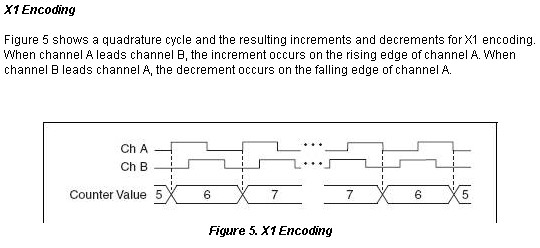
From what you describe, I feel the symptom of the meter backwards never is a side effect of the issue where the meter continuously counts up while in not moving. This really looks like a noise problem, and there are a few small but noticeable spikes in your graphics HAVE you provided. Basically, as long the (Source) Signal led B Signal (to THE), then the meter progressive count. This is for X 1 coding, which I assume that you are using. Look here Figure 5, in virtue of the X 1 section for how this encoding reads your signals of encoding:
Your connections you describe are correct, so it'll be a matter of getting rid of the problem where the meter is incremented on its own which I believe will solve your other problems. Take a look at these links to see if adding filters on the internal counter inputs to the card allows the measurement: Activate the digital M series filtering allowing digital filters for TIO Debounce NOR-DAQmx devices
-
quadrature encoder synchronize the sample
Using a USB-6251 housing measure a quadrature encoder, I will determine the angle that external discrete changes state. I tried to connect the unobtrusive to a DIO of entry and using code CVI PC read the angle of the encoder, when the state change occurs. The problem is the lag time of the PC code that adds up to 4 degrees (with a variability) to the measured angle. An ideal solution would be to trigger a measure in a buffer in the USB-6251 housing when the State of the discrete changes, then read the value in the PC at a later date. Is this possible with the USB-6251 housing?
Thanks Adam,.
I solved my problem by using this idea with the addition of the use of sampling buffered and discreet as a trigger. Engaging the material task also seems to be a good idea, but may not be required.
The installation code looks like this:
Start a way to encode on the counter 1 to control the angle of the label sensor PNP edges
status = DAQmxCreateTask ("PNP Rising edges", & pnpTaskHandle);strcpy (chanString, devName);
strcat (chanString, "/ ctr1 ');status = DAQmxCreateCIAngEncoderChan (pnpTaskHandle, chanString, "", DAQmx_Val_X4, 1, 0, DAQmx_Val_AHighBHigh)
DAQmx_Val_Degrees, 4096, 0,0, "");
sprintf (chanString, "/");
strcat (chanString, devName);
strcat (chanString, "/ PFI1");
status = DAQmxCfgSampClkTiming (pnpTaskHandle, chanString, 1000000, DAQmx_Val_Rising, DAQmx_Val_ContSamps, 10)(0000);
If (status<>
DAQmxGetErrorString (status, errString, 1000);
DAQmxTaskControl (pnpTaskHandle, DAQmx_Val_Task_Commit);
Start the task
status = DAQmxStartTask (pnpTaskHandle);
angleTaskStarted = 1;Read the value of looks like this:
status = DAQmxReadCounterF64 (npnTaskHandle, DAQmx_Val_Auto, 0, npnEdgeArray, 1000, & npnSampsRead, 0);
-
How to read a quadrature encoder, using a PCMCIA card from 6036E?
Hello
I 6036E PCMCIA card and I want to read a quadrature encoder.
I must not use the z index.
My version of Labview is 8.5.
When I try to use the DAQ assistant and choose the option 'angular position' I get the answer that no supported device were found.
What should I do?
Thank you in advance,
Fotios
Hello
Card PCMCIA-6036E has a STC chip that does not support the encoding position because there is no support of Z. It must be resolved in the software and using the edge counting.
Some info on E-cards and quadrature encoding:
http://zone.NI.com/DevZone/CDA/tut/p/ID/4623
http://zone.NI.com/DevZone/CDA/tut/p/ID/2879
http://zone.NI.com/DevZone/CDA/EPD/p/ID/1427
/ Klas
-
Using more 4 for MyRIO quadrature encoder inputs
Hello
I am doing a project where I need to drive 6 motors, each with feedback from encoder quadrature to control the position.
Currently, I use the VI MyRIO encoder, but there is a limit to 4 encoders. What is the best way to read 6 encoders simultaneously with the MyRIO?
Thank you
Timothy
If you must change the FPGA myRIO personality you have a few options.
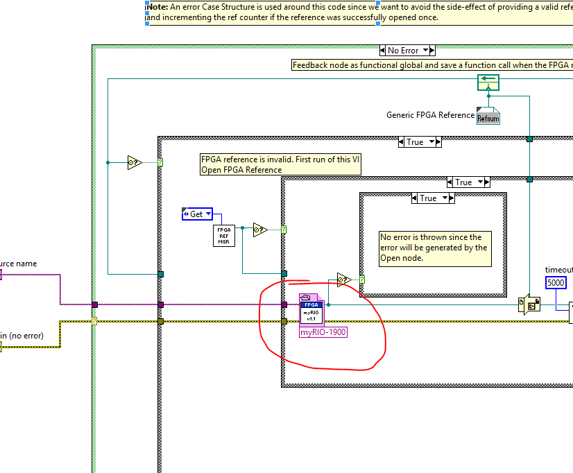
The best option is to start with the FPGA myRIO sample project, add and delete components according to the needs and then build your bitfile. No registry (LV FPGA control / indicators) you do not change will still work with the Advanced IO screws and screw Express. To use the new bitfile (FPGA personality) you must update the Reference of VI FPGA opened in myRIO Open.vi v1.1 (LabVIEW 2013\vi.lib\myRIO\Common\Instrument Driver Framework\myRIO v1.0\myRIO v1.1 Open.vi).
After having done all this time, you use an Express VI myRIO or Advanced IO VI it will use your custom bitfile. All peripheral channels that you left in place will continue to work. You have deleted all channels will always appear in the screws, but will not work (they will probably throw errors when running) and all new channels that you added appear in the screw . New channels, you will need to use FPGA read / write nodes for read and write configuration data and register you created in the FPGA personality. These changes will persist on this computer until you change the Reference of VI open FPGA to the bitfile original.
Let us know if you have any questions about all of this.
Thank you!
-Sam K
Join us / follow theGroup of pirates of LabVIEW on google +
-
cDAQ-9178 & NI 9401 - ASM: incremental Rotary encoder works is not beyond a certain frequency
I use a chassis with a NI 9401 DIO module 9178 cDAQ. I'm trying to convert the output of a rotary incremental encoder ASM (in radians) to rpm.
Sensing head (PMIS4-20-50-240kHz-TTL24V-Z0-2M-S)
Snap ring (PMIR7N-20-50-M-20)
The encoder outputs 2500 pulses per rev (output 5V TTL). The maximum speed which will see the encoder is 2800 rpm, which is equivalent to 2800 RPM * 2500ppr/60 = 116,667.67 Hz in terms of frequency.
Since the NI 9401 of the operations specifications:
Maximum of the input signal switching frequency by the number of input channels, by channel
8 input channels... 9 MHz
4 input channels... 16 MHz
2 input channels... 30 MHzI use only 1 channel, so I'm assuming that the 9401 should be more than capable of handling the 116kHz which the ASM encoder is spit.
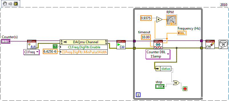
Everything works fine until about 2100 RPM (~ 87, 500 Hz) but then I begin to see a drop in rpm, followed by a flattened behavior, then a slight increase. But never more than 2100 RPM. Our test unit is inspected for other reasons at the moment so I can't produce a plot of the behavior (I can reupload later). I think this must be a matter of aliasing with the meter or something of the sort. I have a digital filter set in place with a minimum of 4.0E pulse width - 6. It is two times smaller than the width of minimum pulse at a frequency of 116kHz (0.0000085714). I don't think this should have an impact on the calculation.
Any suggestions? This value of RPM is essential to our application.
Thanks in advance,
-MB
brown_ktr wrote:
I have a digital filter set in place with a minimum of 4.0E pulse width - 6. It is two times smaller than the width of minimum pulse at a frequency of 116kHz (0.0000085714). I don't think this should have an impact on the calculation.
A 116 kHz frequency, the period is ~8.57 us, but the pulse width half duty cycle of 50%. Ascent/descent time factor, and it is quite possible that 4 US is too long for your encoder signal.
The shape of this graph supports this theory, if we consider that there is variation in the exact pulse of each encoder pulse width. The shortest pulse is ignored when the filter starts to kick in, and the speed of ROTATION increases pulses longer and longer are ignored then as well.
Try to decrease the minimum pulse of digital filter (US 2 or even 1 US) width and see how it goes.
Best regards
-
Hello
I have a cRIO-9014 with a NI9505 DC brushed servo drive module and I would like to program the FPGA to PWM and encoder, quadrature, interfacing using the functions of intellectual property intellectual property mentioned in "CompactRIO Motor Control Basics Tutorial":
DX of encoder quadrature method (FPGA, using SCTL) .vi
Pulse Width Modulation (FPGA, using SCTL) .vi
I did a search at ni.com/ipnet but I could not find them.
Where can I find free downloadable IP cores for the blocks of PWM and encoder to include them in my interface FPGA program?
Thanking you in advance,
Manual
Found by myself (google search!) to:
https://lumen.NI.com/nicif/us/codepowelecguide/content.XHTML
-
Quadrature encoder frequency division dotNet VB Net c#
Hello
After a long search on this forum, I decided to start this thread for dotNet developer.
I have a PCI-6602 with an encoder in quadrature (A, B, Z). The frequency of the pulses is average (10 kHz).
I'm only using the channels A and B.
The function I need to implement is to output all N pulses forward. N is a natural number and ranging from 1 to say 100.
I have no constraints on the output. I may be a little switch or a generation of impulses.
What features I'll call in MeasurementStudio.Net to implement this?
How many counters should I use?
On the registry, my guess is that I have to preload a value in the registry.
Then when countdown counter reaches 0 this in turn does 2 things:
- reload its set value meter
- triggers the generation of output (TerminalCount)
Thanks for any help you can provide

Guy nOTEs for EITHER:
---------------------------------
Moreover, in samples of NOR, squaring does work all the way. I NLE sample "CountDigEvents" with CountDirection the 'Externally controlled' value, backward motion is never displayed. This is because the meter is read as a UInt32.
Hi anthony75fr,
Although there is no support for A, B and Z entries, the behavior you're looking for is essentially how a counter output tasks works. Wouldn't not enough output on each pulse signal of A N (ignoring B and Z)?
If so, you can configure it with only one meter by making a simple change to the example of GenDigPulseTrain_Continuous. The basic shipping example uses the CreatePulseChannelFrequency method. You want to use the CreatePulseChannelTicks method to specify your low and high time regarding ticks of the external signal (regardless of the PFI line the A out of your encoder is connected to). By default, the output of the meter will switch between high and low in a way the number of ticks high and low ticks that you specify (for example, you can set up the meter for the output up 2 ticks and low for 98 ticks, giving a boost all 100 ticks - 2 is the minimum value for high or low ticks).
Best regards
-
9401 counting by quadrature encoder error
I use a 9401 module in a chassis 9188 to measure the position of a tree in 1E6 County/rev. The signal is an AQuadB emulated from an AKD Kollmorgen servo drive. My problem is that when the player is turned on, the noise it makes picked up as very positive figures by the 9401. The player has outputs RS485 but my cable length is short and well armored, so I thought it would work very well. It is wired like this:
9401 CTR1 channel
A +: 9401 pin 20
B +: 9401 pin 23
GND: 9401 commune
The cable shield: 9401 commune
Is this product because the encoder signal is differential, or is my bet to the ground/shield OK? If I disable the encoder entirely the 9401 picks up a zero solid. Should I use a kind of RS485 converter to TTL?
In addition to the advice of John to help protect against digital noise, I also recommend that it would be a good idea to convert the differential asymmetric TTL formally. I had opportunities in the past where I had an ambivalent connection channel differential encoder of 5V to a DAQ card and often, it would work properly. But there have also been moments where differential signals (-) were trying to drift over the other while being tied to the digital earth common DAQ, causing sporadic but strange counting behaviors. At least that's the diagnosis I'm come up with at the time.
These questions disappeared immediately and permanently after putting in a differential to the TTL converter. Here is a link to the productI used (and then successfully reused on the following projects). Just check the specifications of your particular differential signals compared to what this product is to spec'ed to manage.
-Kevin P
-
Learn how to use a quadrature encoder
After many hours of research and assistance, I found a solution to the question. The issue has faced to provide external supply for 9411 modules. The 9411 could apparently not power my encoder of 5 volts. Fortunalty, it's an easy fix. Thank you!
My next question is in what concerns the use of several encoders with my chassis. I spent the day sorting though positions trying to sort through the best way to get there. I'm not sure if I should be using "Tasks" or if I should be using the Express DAQ Assistant. I use cDAQ 9172 and the 9411 modules in slots 5 and 6. I would like to acquire continuous information from encoders.
I'd appreciate any help.
Thank you! ~ J
-
Incorrect values of frequency quadrature encoder measurement
Hello
I use a rotary encoder with the slice has and tranche B and an exit on the ground, attached to an M - series SCB-68 that is attached to an NI PCI-6221.
I use the soul hollow low frequency Freq 1 Ctr.vi I added some time a loop to and is attached below.
I tied to the 9 PFI for the measurement of the frequency of the phase a. (I have attached to the floor to phase B 10 PFI and D GND).
When I run the VI I get a rate that fluctuates wildly to reach as high as 2285714 Hz frequencies.
I used a multimeter between phase has and ground wires and got a rate of 118 ~ 122 Hz which corresponds to the number I want.
Should what steps I take to get the correct frequency in LabVIEW?
My ultimate goal is to find the speed of ROTATION of the encoder that has 64 PPR.
Thanks for any help you can provide.
Hi pd1234,
You probably pick up glitches on transitions (encoders tend to be quite noisy signal sources). These seeds would record in the form of very short impulses, which may be calculated to represent very large frequencies. To resolve this problem, you must enable digital filtering (see the user manual of M series):
The foregoing will cross any superior to 6,425 impulses, but will ignore the little glitches that you probably see.
Best regards
-
program in c to read quadrature encoder did not (NI 6220)
-
What do I need connect a quadrature encoder to a M series card
You are on the right track. Take a look at the 3DGAJHPS file knowlegeBase or do a search for this file.
I use counter zero + PFI8 37 pine and pine PFI10 B 45 + and you use PF19 Z + of terminal blocks. This is the sample VI.
-
Encoder 6351 PCIe and quadrature + voltage sensor.
Hello! All the experts,
I am considering 6351 PCIe to use as a counter and all of catch data.
The question is how to use the input channels equipped with PCIe-6351 quadrature encoder and correspond to voltage sensor data.
1.
Ex)
Each quadrature encoder pulse count, take each value of the voltage with the value counted (Crank angle)
Rising edge of a pulse of 1 2 3 4 5 6 7 8 9 10 11 12 13
Value of sensor vol. 0.1 0.6 0.8 1.2 1.5 1.9 2.1 2.4 2.8 3.0 4.0 4.2 3.5
I would like to know how to get the data using 6351 PCIe quad. function...
2. in addition,.
Do you know how to directly transfer the values of the voltage sensor of PCIe 6351 VI FPGA?
Ex)
Value of sensor vol. ===> PCIe-6351 ===> VI FPGA (analog channel in FPGA)
Could you give some advice?
All tips are welcome!
Thank you very much!
Best regards
Hyo
Hi Hyo,
To the best of my knowledge, the PCIe-6351 isn't any FPGAs; FPGA is generally available on the platform of RIO and R series cards. As such, I'm a little confused by what you mean when you say that you want to transfer the values of voltage for the FPGA VI.
If you use our API of DAQmx LabVIEW, you can use redeclenchables Analog Input to collect a finite quantity of samples of your card for the acquisition of data each time a trigger (e.g. a pulse encoder) is received. This article has a bit more information:
http://digital.NI.com/public.nsf/allkb/14843A49037D7E368625769C006F7A65?OpenDocument
I hope this helps!
Maybe you are looking for
-
instead of a Fox, I get a video
What is an "update" or malware?
-
I want to have my credit card business for my purchases and subscriptions and have our personal card for the rest of the family purchases. Is it possible within a group sharing family? If so, how it is configured?
-
Satellite Pro L20: 37, 5 GB on the disk instead of 40 GB?
I bought a satellite pro l20, which is supposed to have a 40 GB hard drive, but there only a hard drive Go 37.5. is there any reason its slightly smaller than its supposed to be?
-
Satellite L755 - 1 CD a very silent sound from its speakers
Hello I would ask for assistance if there is what I can do to have a very powerful sound on my new laptop Toshiba satellite L755 - 1 CD. I put the speakers at the highest volume possible, but sound from its speakers is very, very quiet, so I can't li
-
No update high priority - post of XP SP3
Fees no installation of XP SP2 OEM CDs no problem. Install XP SP3 Redistributable (used many times before) no problem. After restarting Windows Update, install the Active X control and it came up saying there is no high priority updates. Tried same q