Individually control the digital ports
Hello
I'm getting a weird behavior when I run the VI attached on my computer out of ports digital test/control individually. I have not tested on real hardware because it is not available at this time.
When the code is executed, the output pins are beginning to count gradually immediately (binary counting). Activation of the input pins has no effect which is contrary to the wide of the goal.
It seems to me that the DAQmx function is one that behaves badly, but I don't know why. All I want to do is activate different ports return specified by my selection.
Could someone please tell what I am doing wrong?
Thank you
It is because you are using a simulated device. Readings are just the model of metering for digital ports. Once you get real hardware, it should work the way you expect.
Tags: NI Software
Similar Questions
-
Need help on the use of the PCI-6221 and c# to control three digital Port and an analog of entry
I need to send the digital output at three ports and then read an analog input voltage using the analog card PCI-6221.
I did a c# program to fight against it. I built four tasks altogether. Three tasks for three digital output ports and a single task for analog input.
How can I reduce the time?
Using my method, to 3.3ms in total. And it's slow.
I can build one task for three ports?
What is the best way to the control task to reduce the time of communication with the PC?
Is that possible to save a lot of analog reading entry in the memory of the DAQ hardware and then read it all together from the computer in order to reduce time consumption?
1 million thanks!
Hello
Hi Jin,
To answer your questions, Yes, you are able to configure a task of digital output to use three output ports and PCI-6221 has a buffer of memory FIFO aboard 4095 samples.
I would like to direct you to the example of NOR-DAQmx for c# files located in the following location on your computer
C:\Documents and Settings\All Users\Documents\National Instruments\NI-DAQ\Examples\DotNET2.0
Here, you will find predefined examples in c# that should give you a good idea of how to go about architecting your code to achieve the results you need.
There is also a useful help file which you will find by navigating to Start > all programs > National Instruments > NOR-DAQ > help of NOR-DAQmx .NET Framework 2.0
I hope that this answer is useful.
Best regards
Steve H
-
cannot control the digital state of slider
Hello world
Put a slider on the front panel with the displayed digital order. Then try to change the State of the cursor and the digital control: deactivate and activate the second. It seems that States can be changed independently. But this isn't the case. Digital control gets the State of the cursor...
I tried to change it programmatically with the nodes of property but once again in vain.
Is this a bug? If so, I do not understand why LV would allow users to change the properties of the digital control
 if in all cases, you must create a new one (totally independent this time) digital control.
Thanks for your replies!
Chris
Superfunk wrote:
Hello world
Put a slider on the front panel with the displayed digital order. Then try to change the State of the cursor and the digital control: deactivate and activate the second. It seems that States can be changed independently. But this isn't the case. Digital control gets the State of the cursor...
I tried to change it programmatically with the nodes of property but once again in vain.
Is this a bug? If so, I do not understand why LV would allow users to change the properties of the digital control
if in all cases, you must create a new one (totally independent this time) digital control.Thanks for your replies!
Chris
Digital is a child of the cursor and inherits the value of the slider as well as his State to disable enable.
There is a case where the definition of properties separately are useful. If you customize the control, you can replace the digital with another type of indicator (a dial for example) where it is practical to be able to define its scope and properties (such as its colors of ramp).
Ben
-
writing unique to the digital port
Hi all
A little embarrassed to ask, but I have a simple question. There is, BTW, a general document on DAQMX help pages not only. I always miss the big picture and you have to look in the examples. It works also long examples correspond to your goal, otherwise I have begin to try around. Suggestions are welcome.
To put an end to a digital camera out session I want to write every 1 sec for the 32-bit port p0 of a PCI-6229. See attached picture. Now,.
1: I have everything first to start the task and then write data? Or write data and then start?
2: that I have to "wait until what" before stopping and compensation?
your answers are appreciated!
Mark
For a general overview, see get started with DAQmx .
In your example, it is very good at the job is first started and then write the data.
It is not always necessary to do a task is completed. When you have a static entry as in your example, you don't need it. If you were a continuous, hardware timed generatation, it would be more appropriate.
-
take the digital output USB-6001 always high or low in c
Hi all
I am new to the NI DAQ interface. I have a USB-6001 and I am trying to use this device to control some flowchart in C. What I want to do is:
* set digital output lines with high and low intensity and change their status as needed (in C).
I tested the device NEITHER Max--> Test panels and found that the device is capable to do that. Then I try to do in C. I have checked hace examples and function I use is one called "DAQmxWriteDigitalU32". I have problem in the understanding of its input parameters. I tried something with my own knowledge, but it does not work as I expected. Here is a test I did:
data uInt32 = 1;
Int32 wrote;
TaskHandle taskHandle = 0;
DAQmxErrChk (DAQmxCreateTask("",&taskHandle));
DAQmxErrChk (DAQmxCreateDOChan (taskHandle, "Dev1/port0/line7", "", DAQmx_Val_ChanForAllLines));
DAQmxErrChk (DAQmxStartTask (taskHandle));
DAQmxErrChk (DAQmxWriteDigitalU32(taskHandle,1,1,10.0,DAQmx_Val_GroupByChannel,&data,&written,));taskHandle = 0;
DAQmxErrChk (DAQmxCreateTask("",&taskHandle));
DAQmxErrChk (DAQmxCreateDOChan (taskHandle, "Dev1/port0/$line0", "", DAQmx_Val_ChanForAllLines));
DAQmxErrChk (DAQmxStartTask (taskHandle));
DAQmxErrChk (DAQmxWriteDigitalU32(taskHandle,1,1,10.0,DAQmx_Val_GroupByChannel,&data,&written,));I just want to set ' Dev1/port0/line7' and ' Dev1/port0/$line0"at a high level, but only ' Dev1/port0/$line0' answer me. The second parameter of the DAQmxWriteDigitalU32 function is numSampsPerChan. If I replace (currently 1) with a higher value, such as 100, I see that "Dev1/port0/line7" sends a number of 1 output, then back to 0. So I guess that the problem is just that I understand not all parameters for the DAQmxWriteDigitalU32 function. Is someone can you please tell me how I can set up a line of digital output 1 or 0?
Thank you!
Hongkun
Hello
I finally find a way to do it! The feature works very well, and my problem was not set the data value to write correctly. It seems that if I want to write a 1 to the port0/line1, I put "data = 2 ^ 1" rather than "data = 1", because by default it is the second bit of the port.» Similarly, "data = 2 ^ 7 ' high level to port0/line7. I find that this setting is surprising when you want to control an individual line. It seems more reasonable when you control the whole port. In any case, is to solve the problem!
Thanks anyway!
Hongkun
-
How can I get the digital power meter?
How can I get the digital power meter?
I use a method similar to the example below to measure the market factor using the inputs of a multifunction data acquisition meter. If the duty cycle is 0% or 100% for a given period, DAQ reading times out and returns an error. In this case, I would get the digital state of the counter of entry so I can put as cycle to 0% or 100%. I want to do it without knowing the digital port and line the entrance of counter... for example I would like to continue referencing DAQ/ctrX since I already have this information.
The application uses an M series: PXI-6229 DAQ and LabVIEW 2011 to make a system customized for VeriStand.
https://decibel.NI.com/content/docs/doc-12396
For the moment I wired the block diagram to add a case structure to check the meter ID and string constants to set the identifier of digital input, as they share the physical connection. As much as I can say that makes the specific code for the PXI-6229 (or any DAQ with only two counters that share connections with p2.1 and p) 1.4
I have attached the VI sub.
When the device is used with a different data acquisition, I can add the connection and/or separate control. Looks like at least one will be necessary given that the meter can only detect the edges... I think it was the piece of information I needed.
Thanks for your help!
-
Update Win7 failure: error control of digital signature on applications
I just upgraded my satellite L300 with DVD Toshiba Vista Home premium "s (Dutch version).
Step 1: update Toshiba DVD deleted all drivers as promised
Step 2: Windows 7 Home premium Upgrade DVD installed without problem.Step 3: Upgrade Toshiba DVD won't start help following (translated from Dutch) error:
Can't control the digital signature for this file.
A recent hardware or software change has probably installed a file with a wrong or damaged digital signature...Apart from some basic Windows (IE) programs I can't run, install, or remove all other program-always this error...
Other utilities (wifi for example) just give the message they encountered an unknown error...I tried to update some drivers on the Toshiba site but not a downloaded file monkey runs... (all with the same digital signature error)
What now?
Edit:
I got, I think, to install the drivers of Toshiba in safe mode, but many programs fail to run, install or remove even...
anything that gives the signature error... (ccleaner, revo uninstaller, also all the Setup files downloaded after installation of 7)Touchpad will freeze now and if often, leaving only Ctrl-Alt-Del to reboot the computer
Post edited by: FelixAtagong
So apparently no one can help me...
I found a solution to disable the verification of digital signature in Windows 7, but for that you have to open CMD as administrator.
Guess what, same CMD refuses to open, because it does not recognize the digital signature...How to turn off this thing until I throw my PC in the trash...
Post edited by: FelixAtagong
-
Unforeseen event, captured by the structure of the digital change notification event
Using the specific or similar to http://decibel.ni.com/content/docs/DOC-2280 code (change digital notification.vi) I'm observing behavior unexpected, but coherent structure of the event. The structure of the event capture an event, the first time data is received in the structure of the event; even if there was no change in the digital port assigned. After this initial unexpected event, the structure of the event behaves as expected.
I just wanted to know if someone had a glimpse of it. What is the task of detection of change this event to initialize?
In this case, you would have to ignore the event first, which in my opnion is valid because it reserve no value to a value.
-
The output on the sound output box has no drop downs. The audio output suddenly disappeared and when I went to the 'exit' sound in 'sound preferences' the only thing that would show was the headphones. After that I tried a couple of things suggest that 'Helping Apple', sometimes in digital form & everything that happens you can't change for something else. Things I've tried suggested by Apple press help were the "Shift control option buttons & button / stop at the same time." or press the Option, the command, the P & R key as soon as possible after you have pressed the button On. Hold down until after the second gong during a manoeuvre. This did cause the digital option, but none of these 2 is the one I need. Help
Perhaps, it would be useful to know what that is exactly the one you need. Are get you an external speaker output or anything like that. Also, it would be useful to know the operating system you are using.
-
Somewhere is the sum of control or digital sign for firefox windows install?
Hello
Somewhere is the sum of control or digital sign for firefox windows install?Latest version of Firefox on the CDN server:
- [1020249/questions/1020249] How to use the SHA512SUMS. CSA
-
How to completely control the PORTS COM of BT?
This is related to several versions of the Toshiba, but in this case, it is with 5.10.14FP1, installed on a Windows Vista.
When you start the Bluetooth local COM-Port-Control Panel, the list is filled with eight COM ports:
COM10 exchanger information Toshiba BT Port (COM10)
Com11 exchanger information Toshiba BT Port (COM11)
COM12 exchanger information Toshiba BT Port (COM12)
COM13 exchanger information Toshiba BT Port (COM13)
COM14 exchanger information Toshiba BT Port (COM14)
COM20 HSP Toshiba BT Port (COM20) Manager
Com21 Toshiba BT Port (COM21) HSP Manager
COM22 Manager of HSP Toshiba BT Port (COM22)If I try to delete one of the existing COM ports tells me that it is created by Information interchange or Manager of HSP.
And if I add other com ports to the BT stack, they seem to count for COM40.However, I need to be able to fully control port numbers the specific COM assigned to different interfaces I add... and I most certanly didn't eight predefined ports.
So, I have the following questions:
(1) how to remove eight predefined ports?
(2) how to change the com ports new I add to use COM1 and beyond. (No, port settings normal in the hardware control panel is not an option that is not there).I look forward to your reply...
Daigoro.
First of all I think that it is not a good idea to delete COM ports that are used for communication. If the services according to will not work afterwards. You can of course create new server COM ports if necessary and also configure client COM ports to fit your needs. Just use the custom instead of Express Mode Mode configuration wizard. Now you can determine what COM port should be used for your device. COM1 is often already used by the system, for example the built-in modem, so make sure that it's free!
The tool you are talking about is also available in VISTA. See "Control Panel-> control home Panel-> hardware and sound-> Bluetooth Local COM" for her. -
SMU-6556 - how to control the rise in digital lines (hsdio) time
Hello
Is it possible to control the rise in digital lines SMU-6556 time?
Even in a low frequency 10 kHz signal rise time is 2ns.
TKS,
Hello engfpe,
The SMU-6556 is a 50 Ohm system, which means that the output is source series finished to be 50 Ohms and all our cables and accessories are 50 Ohms. With this configuration, regardless of the flow of data, you should have a clean edge up or down, regardless of the data rate. The quality of the production (edge up or down) on your device is related to the adaptation of impedance of your cables.
The SMU-6556 cannot adjust the speed of scanning by itself. However, you can insert simple passive components to do it for you. I have attached below the images. The first is a diagram showing a way to slow down the edge. The second is the a waveform simulation showing the rate of original edge before it slows down and the edge of idle. This simulation is not the SMU-6556 but rather a generic digital output for concept. In the schema that R1 is set on 34 Ohms because U1.8 has the 16 additional Ohms on the inside. TL1 is the output of 50 ohms simulating the cable on the SMU-6556. R2, R3, and C1 are components, you can insert after the SMU-6556 twist before moving your device/cable. In this configuration from cable to your device is TL2 which is also 50 ohm, but it could be another impedance in which case you would change R3 to match.
You can see in the attached images, you can slow down significantly the edge with this configuration by altering the C1. I hope this helps.
-
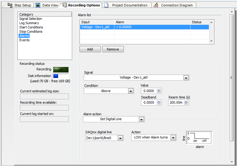
an alarm can be set to control an external device using the digital output?
My employer is considering buying a 6210 DAQ and SignalExpress (we currently use a branded DATAQ device).
Looks like I can use the alarm function SignalExpress to define a logic high or low line, controlling a SSR to stop a pump (a non-critical application).
Can I use SignalExpress in this way?
I know LabView can do, but there is no way that the company appears for him.
Thank you.
Hi Jack, this is Paul with Applications Engineering at National Instruments.
SignalExpress supports the functionality you want.
«Once you have configured your signal to acquire you can go to "Save Options" > "Alarms" and then set the alarm conditions, and then choose your Action to alarm as «Defining the digital line»»
I've attached a screenshot of the example of this configuration.
Note here that I put it down when the alarm turned on. You there are other options, including a rocker.
Let us know if you have any other questions!
Paul
-
How to trace data sent through the serial port by controlling simultaneously the buttons
Hello
I want to plot data by controlling the two buttons at the same time and the draw according to my control using communication serial port, but the problem is that the plot on the graph alternates between the two controls his do not change according to my control for example if I move the potentiometres1 / 1000 and button 2 to 4000 replacing these values on the graph I placed a select control, the problem is still not resolved u can help me please thanks in advance
Regarding
Samatha
-
Control the Boolean commands and generate a corresponding digital output
Hi all
I'm working on a project of activation of the electrode, here, I thought that how could I order an electrode in a time and generate a digital output of it accordingly. I want to replace it with each electrode with a LED on the front panel and generate a numerical value to each LED on the block diagram.
If it can be divided into two parts
1 control the Boolean outputs
Here, my goal is that if I have 5 leds that are used as a Boolean control, must be ordered so that only one of them lights up at the same time and the rest goes off.
I mean for example if #3 was turned on and that the user pressed the #3 #2 should be turned off and only #2 lights.
2. generate the corresponding numerical value
Depending on the position of the LEDs I want to generate a corresponding numerical value, as previously released 3 coming and exit 2 then comes when the second LED illuminates.I ask all participants to this group to help me with this.
Concerning
Why don't you use the radio button control? You can replace the boxes if you want the buttons.
Maybe you are looking for
-
A powered USB hub will support Ethernet / USB?
Wifi in my office is uneven, so I need to wire a Macbook Pro (if that's the term). Because the Macbook Pro is not an ethernet port, I get an ethernet cable / USB. I also get a USB hub with an AC adapter. I know that you should not the ethernet cable
-
Can Apple Store unlock iPod disabled?
My iPod is disabled and I need to be unlocked. I am aware that you can reset it via iTunes on a compurer, but I don't have access to one. If consider in an Apple Store, will be able to reset it? I also don't care about losing the data on it.
-
Satellite P875-S7200: HP Deskjet 1510 cannot connect to the Printer Wizard
When I try to open HP DESKJET 1510 SERIES on my computer it looks like trying to connect to the Printer Wizard but never open and that's why I can't scan anything. How can I connect to the Printer Wizard? On the screen all I can see just - text by de
-
Calendar Gadget different aspect of Windows vista
As soon as I installed Internet Explorer 9, which was in the update for windows vista, the calendar gadget shows the date orange and white background. The white background appears around the orange background. So please help me to remove the addition
-
HOUSE of Smartphones blackBerry SCREEN ICONS/SYMBOLS
ON THE HOME SCREEN. WHAT IS THE ICON OF THE WORLD ORANGE YELLOWISH WITH THE NUMBER 1 TO THE LEFT OF IT