initialize a retroactive loop
Hi all
I am a beginner on labview for a few months. I develop a HCI life-saving data when the user clicks on the buttons. There is a "history of the data record" which saves all the actions performed by users.
I need to delete the history (a listbox multicolonm data) only when a reset button is clicked. But I don't know how to do it. The list box data are erased each time VI and I don't want this behavior, I need to record the history even thought the Vi is stopped by the user.
The way I build 'history of recording data', I initialize a retroactive loop with the multicolonm list box data, but it does not work, I tried many ways.
Thank you very much in advance for your answers.
Thibaud
Any data you want to store between executions of a program must be saved to a file. So when you close the application, your code must store all that she wants to maintain in a file. Then when the application starts, it reads this file and fills the data everywhere he goes.
There are many types of files, you can use for this: binary file (good for all store a single array), the configuration file (OR has a very good API for the use of these), XML, database.
Tags: NI Software
Similar Questions
-
Double retroactive loop via an encoder and a tachometer
I'm building a human rotating Chair for research purposes and want to use a double retrospective loop to remove the backslash. The current system, however, includes only 1 Encoder on load (President) and 1 tachometer and the engine due to the geometry of the system, I can not put an extra Encoder on the motor. I would like to know if there is a controller of axes OR which may take a signal encoder and tachometer signal (speed - analog signal) to close the double loop retroactive.
Please refer to the attachment for the functional diagram of the system.
Thanks for any help.
Hi Ron,
Based on your schema, I don't see a way to do - are you willing to do all the control without firing the values in LabVIEW? If so, then I don't see a way to do this. If you pull the tach values in LabVIEW, you have more options, but none is as complete, having a second encoder.
All movement PCI cards offer analog inputs, so that you could potentially play in the tachometer signal. However, what kind of signal it is up? If its RPM, there is a bit of calculation to actually determine the velocity and I worry not with that many steps in the software, you will kill any 'control loop price' that you may have. I don't think that the system would be too sensitive if you have to shoot these values in the software; and unfortunately it is not "currently a movement card that reads these signals directly."
I hope this helps.
Marti
-
Initialization of the loop after recovery on a new ssd
Hi all!
I want to change the first HD with a new 120 GB SSD on my DV6 HP ENVY with Win8.
I did the following steps:
-Created the system recovery discs (4 DVD)
-Replaced with new SSD HDD-Changed in legacy mode option
-Insert all the recovery discs 4
-At the end of Setup apepar a text saying the system will install all computer will be rebooted several times and it is normal
-Installation process has started and made something display dialogues with progress bars
-Installation process reboot the system for the 1st timeI expect that configuration process will finish but Windows boot up the laptop in a loop to restart and not at the end of installation process.
Can someone help me to solve it? What should I do?
Thank you very much.
Hello, I did a new install on SSD, and I download all want DV6 software and driver from the HP website (http://h10025.www1.hp.com/ewfrf/wc/softwareCategory?os=4132&lc=it&cc=it&dlc=en&sw_lang=&product=5360321). I installed everything and now I work with this laptop

-
Leak memory in a simple loop to save data in the table?
Hello world
I'm trying to set up a simple code to read a certain amount of data in a table at a fixed sampling rate and put these data in a local variable. I'll put this on one OR cRIO-9073 using the scanning engine and the data comes from one NOR 9208 with a speed of approximately 250 Hz scanning, even if it is not really important at the moment.
I made this little test VI which I suspect contains a memory leak, but I'm not able to identify it. The reason for my suspicion is that when I run the vi on a VMWare virtual machine (LabVIEW 2010 on Windows XP) it claims soon that it is short-term memory. Of course, the problem is perhaps elsewhere, but I hope that someone more experienced with LabVIEW programming will be able to find all the bugs very easily because it is really a piece very simpel to code. :-)
I have included a copy of the VI with a screenshot to illustrate.
Regards, Martin
PS my code looks a bit awkward, so if anyone has a better solution, I'd be very happy to learn about it!
Hello Martin,
I would try a different approach to your problem. Currently you reshape your table each iteration of the loop. This means that the allocator memory of LV must find a new piece of contiguous memory each iteration of the loop. You're probably fragment your memory and so short of contiguous blocks of memory, leading to the release of messages from memory.
For these types of tasks, I recommend having an array of fixed size that you initialize outside the loop and then use the Replace table subset in the loop for updating the values. This avoids the problem of allocating memory you use in.
Alternatively, since I assume that you use the local variable to pass data to another loop, you can use a FIFO RT to manage data. A RT FIFO resembles a queue of LV, but it is designed so that you can keep determinism in your application. Set up an acquisition loop that exports data from the 9208 every 4ms in a RT FIFO. Then set up your processing loop to run at a slower pace - say every 200ms. The processing loop reads all the elements of the FIFO until it is empty every 200ms or a number of samples. The RT FIFO is fixed size, if you need to make it large enough to contain at least 200/4 = 50 samples. For more security, you should do several times bigger, maybe 200 samples. You can try different sizes of the FIFO and also to the different periods of your processing loop to your application's specifications.
Using this method you do not have to create a counter to track items, since the reading of FIFO function can tell you how many items is in the FIFO and also when it is empty.
I recommend you the example of Communication of FIFO of RT which comes with LabVIEW to get an idea of how to use these functions.
Gerardo
-
How can I clear the shift registers of sub for loop for each iteration of a larger loop?
Hello
I write a program to concatenate multiple text files. However, I need to treat each column individually before they are concatenated. I use one for a loop at normalze 6 columns choice the largest loop of concatenation. However, the shift registers store data from previous iterations of the larger loop. How can I clear the shift registers of the void loop based on the iteration of the larger loop?
Thanks in advance!
OK, that's fine. are there headers?
In all cases, all you need to do is to place all of the 2D array in the shift register of the inner loop, iterate over the columns relevant to be normaized (use 'index array' to get the column it normalize, put it to help to "replace the subset of table".) You probably want to initialize the outer loop shift register. Use then "building the table" added to the beginning or the data of each file sets.
-
We are working on a program at the point where we want the video to loop over a certain period of time. In case of external action, we want the video to continue to the left the time that we have specified registration and save the avi file. For now, we use only the button instead of external action. However, when we stop the video is not stop recording and save until the next cycle. This means that it will overwrite the record we want to save. Our program is below. Any help will be greatly appreciated, thank you. We have LabVIEW 8.0 version if that helps anyone.
Ahh, gotcha
I would try the attached screen shot to see if it does what you want, but you still don't want to put all your initialization inside the loop, which is just bad programming.

-
y at - it anyway createjs button loop to gotonext frame?
I used gotoandplay to go to the next image. But its horrible for two number of elements.
Then loop will be better. Then go to frame someone help with this.
< link kglad deleted >
function (lib, img, syc) {var p; / / shortcut to the prototypes of reference / / scene content: (lib.destroy = function (mode, startPosition, loop) {this.initialize (mode, startPosition, loop, {b:20,c:21,d:22,e:23,f:24,g:25,h:26,i:27}); / / timeline functions: this.frame_19 = function() {this.stop (); this.bt.onClick = function () {this.parent.gotoAndStop ("i") ;} this.stop (); this.btn.onClick = function () {this.parent.gotoAndStop ('b') ;}} this.frame_20 = function() {this.stop (); this.bt.onClick = function () {this.parent.gotoAndStop ('h')}; this.stop (); this.btn.onClick = function () {this.parent.gotoAndStop ("c") ;}} this.frame_21 = function() {this.stop (); this.bt.onClick = function () {this.parent.gotoAndStop ("g") ;} this.stop (); this.btn.onClick = function () {this.parent.gotoAndStop (")}}}}}}}}})})} d") ;}} this.frame_22 = function() {this.stop (); this.bt.onClick = function () {this.parent.gotoAndStop ("f") ;} this.stop (); this.btn.onClick = function () {this.parent.gotoAndStop ('e') ;}} this.frame_23 = function() {this.stop (); this.bt.onClick = function () {this.parent.gotoAndStop ('e') ;} this.stop (); this.btn.onClick = function () {this.parent.gotoAndStop ("f") ;}} this.frame_24 = function() {this.stop (); this.bt.onClick = function () {this.parent.gotoAndStop ('e') ;} this.stop (); this.btn.onClick = function () {this.parent.gotoAndStop ("g") ;}} this.frame_25 = function() {this.stop (); this.bt.onClick = function () {this.parent.gotoAndStop ("d")}; this.stop (); this.btn.onClick = function () {this.parent.gotoAndStop ("h") ;}} this.frame_26 = function() {this.stop (); this.bt.onClick = function () {this.parent.gotoAndStop("c")}; this.stop (); this.btn.onClick = function () {} this.parent.gotoAndStop ("i"); } }
use:
var tl = this;
TL. Stop();
tl.btn.addEventListener ("click", fl_ClickToGoToNextFrame);
function fl_ClickToGoToNextFrame (event)
{
tl.gotoAndStop(tl.currentFrame+1);
}
-
Programmatically formatting graphic mixed signals
I am writing an FPGA application where I am acquiring data from a unit under test (USE). The PXI-7842R digitizes 3 groups of signals:
1. an analog voltage monitor
2. 5 digital signals connected to the analog inputs (limitation of the pinout of the connector) and converted into Boolean values
3. 11 digital signals connected to the digital inputs
That's a total of 1 analog and 16 digital inputs. I want to show them on the same graph, so I used a graph of mixed signals.
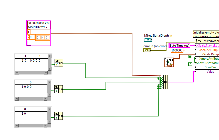
To avoid reconfiguring the graph of mixed signals, everytime I open the app, I wrote a Subvi to programmatically format the chart. I pass a reference to the graphic indicator of mixed signals and try to adapt it to look how I want. The indicator has been designed as a cluster of analog waveform 1, 2 bus waveform Digital 5 signals 1 waveforms digital bus 3 and 3 different digital waveforms. The Subvi is called inside the host VI using a statement box controlled by the 'First Call' function. Then host vi bed a U32 to the target-to-Host DMA FIFO, formats the data in the correct order and the beams while an indicator of mixed signals. During an attempt to format the chart programmatically, I get errors in property not valid which seem to depend on State. Unfortunately, the documentation of the properties seems to be quite uneven for errors I get. The Subvi attached through the following sequence:
1. configure the shared axis and shared properties (IgnoreAttributes, ShowBusseswithLines)
2 set up the area of tracing analog scale Y (superior plot, area 0? documentation is inconsistent on this point)
3 set up the area of tracing digital scale (sector 1) Y?
4. name the digital bus (3 in total, should be numbered 0-2).
5 name the plots
Correctly all steps 1 through 3, but I get an error when you try to set the Active Bus to 0--> ' #1077 Error, invalid property (Bus Active)»
I tried to set the Active plot area to 1 before setting the bus, and I get the same error.
But then sometimes if I rerun the VI host without change, the Subvi ends correctly (even if the area of the scale becomes huge and empty). The only way I can remove the errors is to set the for loops to iterate 0 times, allow the host VI run a few cycles, stop the host VI, remove the constants 0 and run again. And then there is no property errors.
I then tried to create a constant of mixed signals with the correct sequence of the empty slots and it allows to set the MixedGraph::Value property at the beginning of the Subvi. Now error #1077 occurs at the level of the active node before Plot Bus Active node. The thing first on the definition of the constants of iteration 0 does not help when the value property is an initial value.
Here are my questions:
1. the ActivePlotArea property must be configured to use ActivePlots or ActiveBusses, or is that only for sizing and moving areas of land?
2 - is ActiveBus ActivePlot to define first of all necessary to property? for example, if I have ActivePlot = 0 (for analog plot), the ActiveBus property will always fail?
3. what else is necessary for the property ActiveBus of function call?
4. why the Subvi is failing the first time but succeed during subsequent calls without be initialized does not yet reach every time after you initialize (except for loops are set to 0 and Subvi finishes once)?
5. because I show a legend of the plot, I don't want the names of digital signal appears again in the scale box Y. How can I hide the names but to allow the plot area to extend completely to the legend of the plot rather than leave a large area of wasted white space?
Hi Nick,
The reason your Subvi does not work, it's the bus you want to change do not exist when you run.
If you want to run this sub - VI like initializer, you must first initialize all of the plots you will be change.
I've included a small example of how to achieve this by grouping together a constant of analog waveform with some constants of digital waveforms and food nerd in the property "value" Mixed Signal curve.
-
Generator functions agilent modulated the amplitude of the voltage so that the signal
Hello
I'm new on the Labview.
I need to provide a series of tensions with increases step on my device and it repeats again and again.
For example, (5V 0V to 10V 0V 0V 15V) * 5 times
In the past, I turned down on the generator Panel of Agilent 33220 functions by myself.
It's stupid, so I will try to use the Labview to do the same.
I have download the Agilent 33220 Vi function generator has and write a loop for to do this. It can work.
But I found a problem. Each change of amplitude voltage, generator Agilent 33220 A functions will cease to exit and then output the new value.
Because this short period of no output voltage, the dynamic behavior of my device will be destroyed.
How can I do?
You made a classic mistake. You have placed the Initialize and close inside the loop. The Initialize will, by default, perform a reset feature, which disables the output. Initialize outside a loop, do your stuff inside and close the loop.
Regarding your code: I strongly recommend looking at the model of ramp function. It seems you want to increase the parameters of voltage to zero between the two. This can be easily done by creating your rising tensions ramp and then creating another matrix of the same size zeros and interlacing then the two tables. This will give you a complete range of voltage values, without to need two loops and determine what step you are on, etc. etc. For example, the following code will give you 5, 0, 0, 10, 15, 0 sequence fairly cleanly:

In addition, never perform a comparison of equality on the floats. If not, you owe me nickel one another in my retirement fund.
-
not enough memory to complete the operation
I looked in the forums for "memory to complete operation" error and despite the advice that I found, the error always happens.
I'm using LabVIEW 2012 to try to constantly monitor our system, recording temperature, power, etc. vs time (values obtained by acquisition of data USB-6008). The data being saved to file, is every 60 seconds using a small table (no problem here). Allocation of memory time/sleeves typical LabVIEW is about 180 MB (4 GB of RAM on computer).
The issue that I feel is related to our wish to display these data on a chart for long periods of time. The current iteration of the code works as follows.
(1) we have 2 XY charts with 2 slots of each.
(2) for each parcel, I'm initialization of clusters of berries of 2 100 000 (XY pairs) that are related to the shift registers. I know it's bigger that can be displayed on a chart, but I am currently more concerned with reducing the number of data copies.
(3) every 10th data point is added in the tables using one up Bundle/Unbundle element with a 'subset of table replace. " In other words, there are about 8640 points per day. (One day is the shortest duration usually read)
(4) for the two traces on a XY Chart, two groups are combined in a table (using the table to build). I think that's my problem here. Since every time I update the charts that LabVIEW must allocate memory for the 4 XY plots. (I'm correct here?)
Decimating the additional data during research on several days will reduce the amount written in the plots. However, this creates copies of data. It is useful in this case?
Instead of initializing 4 groups (1 for each plot) and combining in the tables later, it would be better to initialize the array of clusters of berries (2 lots per chart) and update the data by "index / unbundle / replace the subset of table / bundle replace table subset" series of operations?
Nothing obviously bad jumps to my, but this could be why it works for days sometimes. A few things to try:
(1) the section where you overwrite the oldest 3600 data points and rotate tables has code to initialize a new table. I propose this initialization outside the loop to make sure that only do you it once. You could always simply replace the elements in the table with a value of NaN.
(2) I would try to get rid of the build tables as you pointed out. Initialize these berries outside the loop and replace components as appropriate.
(3) build you tables of Irr and time according to the table of the construction and reset them once / day. You can try those external booting as well.
(4) If a problem occurs and the file write crashes your queue can fill. The dequeue item is already waiting for data before it does anything, so I don't think you need the delay in the same loop. This could help the dequeue catch up if the queue is large. You can use a vi Get Queue Status to display the number of items in the queue on the screen. As long as it is not hidden by the error message it could give you an idea if the queue is the cause of your error. You can also access the queue size to see if it develops.
(5) If your data acquisition loop error handling is not good, a mistake it can cause the loop to run as fast as possible. If you have added the 1000ms wait just to show that this is not a gourmet loop, so this could easily be the cause. I do not think that the Renault USB are very reliable, so try to use a days may run into this error.
I hope that it becomes at least you said in the right direction. My bet is on #5

-
With the help of two channels of my 6623A
Hey there, I'm looking for help reguarding a power supply HP 6623 A DC using Labview 9... I'm working on a project where I need to control all 3 channels of power and switch back and fourth to change their output. I tried to change the code in the example, but it will only be 1 channel and clear the other. I can't get the two simultaneously. Thanks for your help
OK, let's take a step back.
You control a single instrument. Therefore, you shoud have only 1 resource that is initialized once and closed once. You must perform initialization before your loop and close after the loop.
What I recommend here, is that you use a Structure of the event for the control when you send commands. The idea here is that you only send orders when your settings change really. You can use the case of timeout to make the statements.
And since you claim that you're new, here are some tutorials that you may find useful.
Introduction of 3 hours
Introduction of 6 hours
Bases LabVEW
Paced self-study for students
Self Paced Training beginner to advanced, required SSP
LabVIEW training Wiki
OR learning
Getting started with products OR -
eror 20079 during the parameter base control
I'm doing based parameter théorie control (e.g. If data greater or equal to 5 valves must be closed for 2 seconds and then open). what I've done I have attached as bmp file. his Don eroor 20079 Daqmx read error. Please guide me
The way that you described how VI looks are different, first, do the initialization outside the loop. You get the error may be due to the initialization of every time when the appliance is already initialized. logic of 2 seconds also not good.
-
How to write constantly to analog output and read from analog inputs
Hi all -
I had a question about writing continuously to analog output reading simultaneously an analog input.
It's my first time to post a message to the community, so please let me know if I made mistakes.
I use Labview 2011 with a NEITHER-DAQ USB 6215.
I'm looking to generate a waveform and write it continuously in an analog output. It is then connected to an entry on the acquisition of data, where I am trying to sample the analog signal. (I realize, there is a system of trivial, but I'm hoping to build on it once I have run).
The task of reading from the analog input works fine, as I tested it in several other cases. I have a problem writing to the analog output.
For this task, I tried to follow the "Gen Cont Wfm Clck Int' VI to generate the wave form and start the task. I then try to write to the output of the analog timed loop. However, it does not seem to transmit a signal and doesn't give me any errors.
I have attached the VI but also a screenshot.
Please let me know if anyone has any ideas. I would really appreciate the help!
Thank you
Peter Borgstrom
We will review your tasks one at a time. First of all, the task of generation/Analog output Waveform. Generate you a waveform (I'm unsure of your VI if it is a fixed waveform or not) and send it to a defined output function to produce a waveform continuously, using N-channel and samples of N (where you set not these previously). You should not put this inside has timed loop, as the DAQ hardware has its own clock - if you simply put it in a while loop (with a stop to break out of the loop), the loop will call the function for the first points of N, wait until all N have been taken out, then call it again to another N points (up to what you press Stop).
Now, suppose that you have the output connected to a load voltage (say a decent resistance). You can wire the input terminals of your A/D converter through the same load and set up a similar analog input loop, running in parallel (i.e. in its own independent of the OD loop, while loop). You pourriez start together (with, say, a merged error since the initialization code line loops HAVE and AO become lines of error in "loops of sampling" described above), but you might want to delay loop (a little) the AI so that the OD has a chance to set the voltage before the bed.
I hope this helps.
BS
-
void / results vi selected - can I clear out sub - vi after every call?
I'm new to Labview and faced with a sub - vi that I am using. I would be very grateful for any help you could offer!
I created a subvi, which, given some input parameters, will generate a table of values MxN (M = lines, N = cols). This is illustrated in the extract attached 'array_creating_subvi '. I wrote a simple vi to call this sub - vi (see attached extract 'main_vi') which should give the input parameters for the sub vi, display the table resulting from the Subvi 2D generates values and also return the size of the table that was generated. The first time that the main vi is running an MxN array is created. The second time, it runs a table 2MxN appears - the newly produced table has been added on the lower part of the table created in the previous call... and so on.
I tried to use the function 'demand release of memory' in both the main program and the Sub - VI, I tried reinitilizing all values by default before running the main vi (both in the main sub - VI and vi) but nothing seems to work. I am completely at a loss and would really appreciate any advice you might have
 )
)You can initialize your array looping upward and have a shiftregister more to the outside for loop.
-
probe shows not executed on some son!
Please help - it seems to be a bug in labview.
I have a no concave vi with enable debugging.
I have a problem to debug several threads - when I put the probe on them - the window of the probe shows "not executed" even though I'm sure
they run because they update of the indicators.
I don't know if it's related - but this happens only in my loops of communication rs232 instrument data.
all the other loops in the VI (which is a very large VI with many other loops running simultanesly) can be debuged without problem.
don't tell me to put the code because I can't.
Thanks for your time
Guy
Ok
After several hours of investigation, I managed to isolate the problem.
I think this is a bug in labview 2012.
I don't know why, but it seems that a node feeback (with external initializer the feedback loop and not z transform node) within my time loop caused the problem.
After removal-problem gone.
It's weird because I have other loops which has the exact comments without problem nodes.
I hope this will help others
Greetings
Maybe you are looking for
-
Need advice on my 5 c 'Notes' app iPhone
Hello, being a complete technophobe that I really need help; I have an iPhone 5 c and whenever I'm in the "Notes" application, I am driven to the home page, after 20 seconds and when I type up, it takes me to the 'files' screen, if I press 'notes' an
-
Satellite A30: Cannot detect internal modem
I have a Toshiba Satellite A30. The internal modem was working fine until a few months ago, when I moved to town. Now my computer can not detect the modem at all. Please help me!
-
7073ca: HP DV7 7073 - corrupt BIOS
Hi all My Pavilion DV7 (7073ca), running windows 7 Professional, recently started acting very strange and then becomes unbootable. I recently installed an SSD with the cloned, OS, but I do not clone the partition HP_TOOLS (mistake #1). When you try t
-
Satellite M70 - no hidden restore partition
I noticed that many laptops Toshiba hidden partition and recovery DVDs either. I have no partiotion hidden, only the recovery DVDs. Is this normal?
-
InetPing return false system available
I have an application where I use InetPing to verify that a network exists before testing network-centric. He has worked successfully, to the best of my knowledge for some time (months). However I was just run the test and observing the performance