Integrate on the wavelength spectrum
Hello
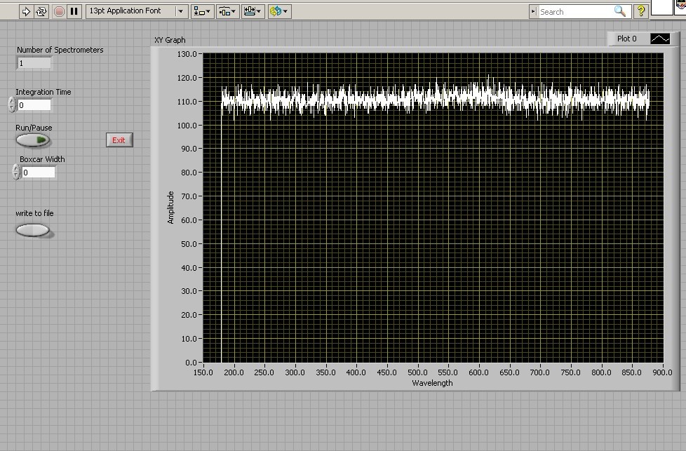
I'm using the ocean optics s2000 to acquire some of the spectra. What I'm trying to do now is to integrate the frequencies between two wavelengths, but do not know how. The sampling frequency is 1 MHz and so the spectrum is constantly updated (I guess). I try to get the full instant result between wavelength, for example. 600 nm and 650 nm on the figure below. Any suggestions?
Thank you!
You can use the "unequal integration" VI. This programming point of view.
From a physical point of view, it might be more difficult. Each of your samples of data is probably convolved with the spectral characteristics of a filter or a Monochromator to be taken into account.
See you soon
Edgar
Tags: NI Software
Similar Questions
-
'power' and 'size' in the power spectrum?
When I choose "power at the stage of the power spectrum, numbers in my data were negative. I don't understand why. What is the difference between "power" and "ten factor"?
And what are the "dB" and "linear" in the average of actual size selection? "DB" means the following equation? Vnorm = 20 * log10 (Vnorm)? 'Linear' means greatness?
Thank you very much!
-
Output power of the frequency spectrum
Hello
I have a pretty simple question. I m using the power spectrum of FFT and PSD vi. and have trouble understand output frequencies. If I understand the first line is DC-value and delta frequency then describe the following frequencies. But when I put for example in 8 points say sampling frequency of 4 Hz = 2 seconds of data to analyze, I'll be back 4 lines of data (including 0). If the first is DC, then the 2nd should be 1 / 2 Hz 1 Hz = 3rd place and 4th place = 3 / 2 Hz, but what about the frequency of 2 Hz Nyquist, why Don t I get this one? or is there something I don't understand?
I also tried the example of Units.vi of FFT spectrum and can understand, but I still Don t get it.
Help, please!
Best
Jesper
FFT returns to power in frequency bins. The frequency of the bins is determined by the Fs (sampling frequency) divided by N (number of points), from DC (0Hz). For your case, the table returned would be:
Bin 0: 0-0.5 Hz
Bin 1: 0, 5 - 1 Hz
Tray 2: 1-1.5 Hz
Bin 3: 1.5 - 2 Hz
So effectively Bin 3 holds the power of 1.5 to 2 Hz (which contains your Nyquist frequency).
-
Unit of the y-axis of the power spectrum
Hello
I am acquisition of acceleration of an IEPE accelerometer. Units of the axis y of the signal in the time domain are in (g). The signal in the time domain is then injected into the Spectral VI Express measures to obtain the power spectrum of the signal. In the Spectral Measurements Express VI, I put the results of linear and the window (Hanning). My very basic question is: what will be the units of the axis y with the linear option power spectrum and how can convert their return to unit (g). If you provide an example of calculation that would be very appreicated. One of my simple code is attached.
Concerning
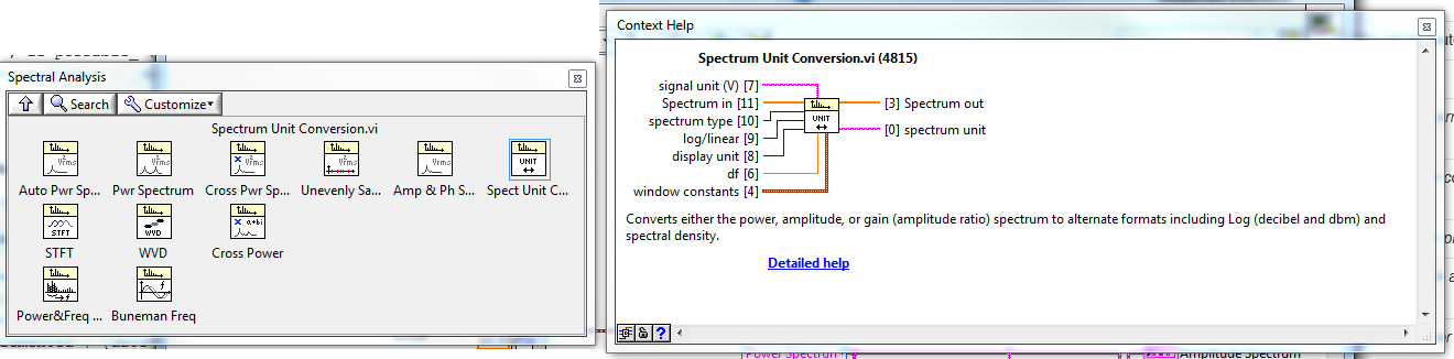
Unit Conversion VI spectrum lie in LabVIEW palettes: functions > Signal Processing > spectrum analysis
-
Data storage of the optical spectrum for several points and recalling a specific
Hi, I'm working on an installation of measurement of the optical spectrum automated for a summer project, I have been using labview for about a week now and have had bases for stage motor control, but I have problems with the data management...
I'm looking to store data such as those acquired with an optical spectrum for several XY points Analyzer and recall the optical spectrum for a specified point? Currently, I am looking at writing to the file of measure and reading of the measures such as the options file, but I'm not sure how to name each piece and the data and to recall them correctly. Are there examples where this has been done? any help will be greatly appreciated.
I use a connect Yokogawa AQ6370 via ethernet, LabVIEW drivers are provided for this, but I can't find the screws provided here is
Thank you very much
Asiri
Not clear? Ask at your

-
Why the FFT spectrum gives values of RMS?
Dear Sir
I want to get the value of crete to crete on FFT spectrum. But he gives values of RMS. Can you please guide me how can we peak to peak on the FFT spectrum. Attach the vi is for example.
Kind regards
Urfee
Tronoh wrote:
Dear Sir
I want to get the value of crete to crete on FFT spectrum. But he gives values of RMS. Can you please guide me how can we peak to peak on the FFT spectrum. Attach the vi is for example.
Kind regards
Urfee
What does it mean to get the value of Ridge Crest of a FFT spectrum? [I understand getting the value of P - P of the signal ...]. Note that the parameters on the average you attached (which shows mean quadratic value, by the way) refers to the way in which the Spectra will be averagedand RMS is logical (logical) in many cases, but I'm at a loss to understand the average peak-to-peak here...
BS
-
How can I synchronize a new track to the audio spectrum, effects and audio amplitude logo
Hello!
How do I paid recently a graphic designer to create a sound model for my music on youtube channel, but the problem is that I do not know how to synchronize a new track to the audio spectrum, the effects and the logo of the audio amplitude (pumps logo to the sound of the track that he gave me in the layout) but I would like to synchronize it instead of a new track at all. [Please help:]
Click on the tab "LOGO of MOUNTAIN" or double-click the color icon in the Panel layer to open the publication.
Import the audio file in the project Panel.
Click on the new audio file in the project Panel to highlight.
Click on the 'old' audio file in the Panel layer to select it. (they are both put in evidence now)
Now, hold down the 'Alt' key and then drag the new audio file of the project on the old audio layer panel in the layer panel.
Doing it this way will automatically do all necessary connections to the old file to the new file.
Or... you could just drag the the new audio tracj in the Panel layer compositions 'sound '.
Select the solid layer that has the applied Audio Spectrum effect.
Then in the Audio Spectrum effect setting pane, find the list at the top of "Audio Layer" drop-down list, click the menu drop-down and select the new audio layer.
-
How can I change [frequency] on the audio spectrum?
How can I change [frequency] on the audio spectrum? I really need an easy way to solve this problem
After Effects has a very limited set of audio tools. Your only option to change the Equalization inside AE is to apply one of the equalizer and then before dialing the audio track that you use to the reader of the Audio spectrum. It's a little awkward, but it keeps all the controls inside the AE and keep them editable.
Personally, if I want to isolate the frequencies I always use the hearing to create an audio layer duplicate that has been optimized for the effect that I need to generate audio.
-
Impossible to change the colors of the audio spectrum
I have a simple (I think) problem with after effects CC. When I put an adjustment layer with curves of fx on top of my audio spectrum, it will change color. In parameters of fx audio spectrum when I change the color inside and outside, it works, but I want to use my adjustment layer. Any suggestion would be appreciated, I'm working on my uni project and the deadline is tomorrow morning!
I forgot to mention that in your second screenshot, you have your curved effect applied before the Audio Spectrum effect. Thus, even if she had to work, it must occur AFTER the Audio Spectrum effect.
You need the color of the audio spectrum that results be gray. One way to do that is to apply a fill effect after the Audio Spectrum effect.
This tutorial tutorial can give you some ideas better because it looks like what you're trying to do.
Also, you can use the new Color Vibrance of video Copilot plugin (free) without using the fill effect.
-
How to reset the HP spectrum Ultrabook CTO 14 t-3200 Power-on Password
I have a HP spectrum Ultrabook CTO 14 t-3200 with Windows 8. I put a past under tension, but apparently fat fingers part of it because it does not work when I use it. I get a 'Broken system' 21296174 code. How can I reset or bypass this?
I have never seen anyone report get different codes, does not mean that it didn't happen. I checked your maintenance manual to see if a procedure to clear the BIOS pw was an option, has not found a way.
I would contact HP support for service > >http://www8.hp.com/us/en/contact-hp/contact.html
-
spectrum x 360: how I see the new spectrum x 360 with damaged quickly view
My spectrum x 360 finish guarantee the screen apear a black vertical line like the attached picture, how can I repari it. It's sobore for the superior quality of the Tower
I brought your question to the attention of a team within HP. They are likely to ask for information from you to get your information or product serial number. Please search for a private message from a contact HP identified. Also, remember not to publicly post information and series numbers.
If you are unfamiliar with the operation of the function of private messages of the Forum, this post has instructions.
-
Hello
I have a question about BER and SNR and I would appreciate your help.
I have a power Spectrum (live with the presence of interference) and I would like to know in what parts of the spectrum, I can achieve a target BER (lets say 10th-3)
My suggestion was to first determine the signal investment ratio on the graph (for BPSK) and then search for available positions in the spectrum that can give me this SNR
So say for 10-3 BER, en No. DB 9 (on the graph)
If Eb (dB) = 9 (dB) + No. (dB) or Eb (dBm) = 39 (dBm) + No. (dBm)
now my questions are?
1 - instead of BER can I focus on NRS and are my calculations correct?
2-noise background in my power spectrum is observed from BDP-110-130 dBm is not a value constant .what should I do in this situation to find Eb?
3. What about interference? because WLAN is perhaps the received power - 50dBm in this situation that the SNR appropriate therefore to achieve this BER?
is it correct to say Eb should be = - 50 + 39 (dBm)
I thik find positions them avaiable in the spectrum (especially 2.4 GHz) to achieve a certain BER or SNR should not be as easy as I think.
Hi tintin99, the calculation seems to me.
For the second question, I don't know what application you are considering, so it is difficult to answer. If you measure performance to highlight, I'd go for the peak noise. To help us to give an exact answer, you provide more information about your application. For example, NEITHER-6115. The following link will be useful: NOR-6115 noise floor.
In case you're only interested in theoretically calculate the background noise, please check for the radio receiver noise floor. According to the definition, you can calculate the background noise as follows:
Background noise =-174 + NF + 10 log bandwidth
Where NF is the noise figure.
I hope my answers help. Still once, for questions related to the concepts of communications, please try discussion forum, I mentioned above. RF meter of NOR, please post to measure RF devices
-
Get the value of the frequency of the power spectrum
I'm rather new to LabView and want to measure the frequency of the peak in a spectrum of power of a real signal. In addition, I want this value of frequency and amplitude to save to a file. Right now I am able to trace a spectrum of power using an express VI, which gives me the correct frequency value in the graph.
However, I'm not able to extract the value of the frequency with different screws, I found in LabView after browsing through the various discussions in this forum. Can someone tell me please in the right direction? I use a digitizer NI PXI-5124 to record the signal in a rack of NOR.
If it is the dominant frequency you are looking for you can use the vi extracted a single signal. You can also change this vi to include the details of the search if it isn't the dominant frequency, I have not included it in my example, but you can check it in the help file.
Ian
-
Coercian dot on the power spectrum
Hi all
Was just curious to know why I have a point constraint on my FFT power spectrum when it fed a waveform? I thought (and detailed help is agree with me) that a waveform has been the type of entry required. There may be more going on here that I realize, but clearly I'm not.
As a sidenote, I'll you this because I replace an express VI in an application, that they gave me to end up and the express power VI spectrum seems to give results that are disabled by the square of the input function. OK then that sentence makes little sense, what I mean is when I plug a function up to my DAQ board generator and supply a sine to a known frequency spectrum of power express VI sets out 16 Hz instead of 4 Hz, 2500 instead of 50. The spectrum of normal power VI works fine. Do not Express VI anyway but just curious.
Thanks in advance!
Is the matrix Y DBL? SGL or EXT would produce a dowry of coercion.
Lynn
-
How to increase frequency resolution in the power spectrum?
All,
I work on the analysis of data GET vi, and manage mucho when it comes to display a simple power spectrum which gives a precise simulation of sine wave frequency I use now. Most of the brain waves are between 1 to 50 Hz, and so I try to get a resolution of at least 1 Hz frequency. However, no matter what I do (increase the sampling frequency, use different sub vi and blocks), the chart plot only in frequency of 10 Hz increments. I know this must be a simple problem, but I can not find good documentation on this and would appreciate any advice anyone could give on this problem. I'm racking my brain here!
Nick
You need to acquire a second data to get the 1 Hz resolution. The increase in sampling rate only increases the bandwidth that covers the FFT.
Frequency resolution = 1/sampling
Scale of frequency rate of sampling/2 =
For your application, you will need to have a sample of at least 100 Hz rate. At this rate, you must purchase 100 samples to get the 1 Hz resolution. At the 1 kHz sampling rate, you will need to acquire 1000 points for the 1 Hz resolution.

Maybe you are looking for
-
How to set paragraph margins in a document
I would like to define paragraph L & R margins in a word processing document, but I find only the margins of the Document in the Inspector. If I try and create a new section for paragraphs with new margins, a page break is created. Help pages 'Defin
-
I added an external keyboard and an external monitor to my HP Envy laptop m7-n011dx. Both are recognized by the laptop, if I leave the lid open. When I close the lid, the computer goes into mode 'sleep', and I can't use the laptop with the keyboard
-
Problem with loading of updates
Whenever I try to install the updates from the window I get this error message:"WindowsUpdate_00000646" "WindowsUpdate_dt000" I have Windows Vista.Could this be the problem. I have this problem when I try to install the update of security for Microso
-
Remember - This is a private forum pubblico per cui non pubblicare information I just numeri e-mail o Teléfono. Idea: If HOT IT PROGRAMMED WHEN BEGINNING a WRITE I have programs if sono verificati problemi con Error di messaggi The comments related a