Internal resistance on 2800 backplane?
I have a new switchblock 2800 OR 2811 A card that I connect via a Virginia Panel ITA. Before using the switches for my project, I was testing the switches and I found a behavior that I wasn't expecting. I have a 4072 digital multimeter connected to SwitchBlockDev5 c16 and c17. When I connect c16 and c17 through another line in the first attachment (c5 is the other line in this example) then I measure resistance of ~ 200 ohms (I expect something close to 0). When I cross the lines from the bottom of the basket and connect the DMM leads it as in the second setting (where the lines are connected on SwitchBlockDev6 c18) then I measure Mohm resistance ~ 168 (I expect something close to 0 or 200 ohms), if I pass the DMM wires on the second configuration then I get - 4.45 Mohms under my measure. Can someone explain what is happening and what the circuit looks like? Is there some kind of framework, I can do in the software that will give me my desired values when I do these DMM measures?
Thank you
Chall
Chapin,
The 200 ohms you receive is probably because you are using the cable "SH96F - 96M - RES. There are two cables NI SwitchBlock, a 'normal' and a cable with resistance of 100 ohms additional linked internally to the cable by column [two whole columns = 200 Ohms]. This additional resistance of 100 ohms is used to prevent the current overloads. If you use the cable "SH96F - 96M - RES ' and you want to read 0 Ohms, you need to replace the cable with the cable"SH96F - 96M"'normal '.
168 M Ohm resistance you measure is probably due to the missing safety lock Resistance on your test setup. If the resistance of safety lock is missing, connections between the relay in your support of 2800 cards will never connect.
Tags: NI Products
Similar Questions
-
Measure the resistance with PXI DMM 4072 on different frequencies
Hi all
I tried to get on board various and unable to find solutions for that. I'm trying to measure resistance using NI PXI-4072 on frequencey 1 kHz, but not luck. When I try to use Agilent LCR meter I see the correct value of the resistance.
I've seen a few posts on this but don't have no satisfactory solutions.
In above post, someone said that I can use 4072 DMM OR digitizer, does not have a lot.
Can someone please provide the right path for me to solve this problem.
Thank you
Hello Puneet_K,
I checked the data sheet and the method of measurement described in the specifications of the NI 4070/4072 http://www.ni.com/pdf/manuals/371304g.pdf; indicates that the ability is measured using an alternating signal and select the test frequency range, for example 3 kHz, 1kH or 91 Hz. The resistance is simply measured using a DC signal, and it is often sufficient to measure the internal resistance of a battery. If you need a more flexible control for the measurement, you probably get a card like the function generator and then set a multimeter to measure the voltage and another DMM to measure the current and calculate the impedance of these values.
I hope this helps!
Kind regards
-Natalia
-
Read a resistance of the diode by vs NI USB multimeter
Hello
I read a resistance of the diode at some entrances to supply voltage
and I found that
to 0.2 V
the value of resistance by NI USB-6212: 200 ohms
the value of resistance of meter: 2 kohm
0.5 v
the value of resistance by NI USB-6212: 500 ohm
the value of resistance of the multimeter: 5 kohm.
Could you please let me know why the values are different by 10 times?
Thank you.
No - we can't measure the resistance in this way.
To measure resistance, you normally spend a current known and then measure the voltage. A DMM will be repeated by generating a little known current and measuring the internal tension. If you provide an external voltage thus, DMM internal resistance measurement will not work.
For the LabVIEW - The USB-6212 can measure the tension. If you want to measure resistance, while the unit is plugged, you need to know/measure current (for example through a shunt resistance) and the tension and then do R = V / I for the resistance. I don't know what the argument of type 6212 if you try to perform a measure of 'resistance', as it is not a source of internal current.
Oh, I thought that this all seemed familiar - here's a similar thread: https://forums.ni.com/t5/LabVIEW/daqmx-resistance-measurement-6251/td-p/3267084
-
Error-50303 occurred at ELVISmx_DAQmx create channel %2528AI-Resistance%2529.vi%253A1
Hello
I used the myDaq in my electronic class earlier today and the suspect, I have damaged the myDaq. I had an external power supply connected to my circuit on a Protoboard - the circuit was not directly related to +/-bus on the protoboard, but the Council itself was hung in the myDaq.
I noticed this caveat statement myDaq Manual:
Power supplies
Caveat! Do not mix the power nor myDAQ with power of external power sources.
When you use an external power supply, remove all connections to the power supply terminals on
NEITHER myDAQ.Since then, I get the following error message when I try to take my multimeter (NI Elvismx) readings:
Error-50303 occurred at ELVISmx_DAQmx create channel %2528AI-Resistance%2529.vi%253A1
This message means that I damaged the myDaq? Could I have generated too much current with voltage circuit / applied and brought to save in the myDaq? If so, it would damage the myDaq or are there internal safeguards in order to protect the device (i.e. recognizing when internal resistance reduction) and trigger an error code (i.e. could reset you HAVE resistance)?
I am new in the field of electronics, so please forgive me for any obvious incorrect statement above!
Also, I went then to download the troubleshooter of myDaq - I managed to unpack the file, but it would not be completed installation (i.e. the 'next' button is grayed out on the summary screen, the only options to the choices were 'save' and 'Cancel').
Thanks in advance for any guidance/direction you can give me!
Sincerely,
Melissa
Found a miracle solution!
Under the tools NI MAX button, there is an option to select "reset Configuration data".
After selecting this, he reset the Configurations OR and restarted my computer. I noticed that when I reopened NI MAX, I had more options to choose when I click on the myDaq device (i.e. before I could only choose 'Save' and 'Refresh'... now I have more options including a reset, self-test function, test panels, etc.).
I was able to use my features NI Elvis DMM and no longer see the error message (just did a simple test with a resistance).
See you soon!
-Melissa
-
NEITHER 9234 with quasi static analog voltage
Hello
I have a NI 9234 (4 channels + / IEPE 24-bit 5V) attached to a chassis cRIO module. This module is ideal for accelerometers and microphones where the tension is in constant evolution (ie; measures of variation rates).
I also have a module OR 9237 (4 channels 24-bit full-bridge module analog input) attached to the same cRIO. This module is ideal for measure variable voltages of strain gauges (quasi static and dynamic loads).
The attached graph shows the two channels, collected synchronously, but as you can see the (red trace) cell breaks down (as it should), but then drifts back to zero on its own, when in fact it should remain low just like the extensometer is beam. After all, the two sensors are physically secured.
Q1: Would that have something to do with AC/DC module 9234 internal coupling?
Q2: Is it really possible to collect "quasi static" ongoing tensions by using a NI 9234 module?
No explanation as to why this occurs, or if there is a way to remedy this would be appreciated.
Kind regards
Andreas
Coupling AC/DC must do a lot with your question. In mode AC voltages static will be fitered outside and the 9234 measure indeed only change voltages. In DC mode, the voltage goes directly to the AD converter and you can also detect static tensions.
A minute of Googling gave me the answer, this load cell electric piezo can measure dynamic changes, as any charge will escape the path the lowest resistance and the signal will go to zero after a certain time. I guess the other device you were using higher internal resistance (which is relatively low on the 9234), so it takes more time to what he flees, but he also took on the picture you attached your second try.
Here you can find more example under the title
"WHY ONLY DYNAMIC FORCE CAN BE MEASURED WITH SENSORS OF POWER PIEZOELECTRIC"
http://www.PCB.com/techsupport/tech_force
Andreas Jost
Technical sales engineer
National Instruments
-
Negative results with strain gauges
When I run my VI the results are always negative. I use the NI9237 with the NI9945. I wired my installation as one quarter bridge. There are three wires from the strain gauge. I went on the wires and I think it's okay / characteristics of NEITHER. Is there something in the MAX that I should be looking. Not sure why the values are negative.
Thank you
Harry Stone
Hi Harry,.
There are a few things I want to clarify:
-Traction deformation is positive and compression deformation is negative, what is described a high level in the tutorial below.
Strain with gauges
http://zone.NI.com/DevZone/CDA/tut/p/ID/3642As strain compression is negative, you would see negative within MAX results if your strain gauge knows any compression. Please keep in mind that a shift can be associated with each transducer, that's why some sensors use a calibration certificate. It is produced by the manufacturer and is provided with the sensor as is the specific sensor. The sensor goes through a testing process to determine its actual response compared to the ideal. In this case, a scale of table can be created to include these values.
How to do a custom able scale & Automation Explorer (MAX)?
http://digital.NI.com/public.nsf/allkb/3F6558112FD2C776862575B5004F7F87?OpenDocumentNot all manufacturers of sensors provide a calibration certificate. Or you can create your own table by placing known quantities of pressure, force, etc. on the sensor and map it to the corresponding voltage, or you can create a linear scale in MAX adjusting the intercept (b) the value necessary to remove any compensation.
You use the NI 9237 that compensated supports deletion. A null offset is executed with the sensor fixed without load placed on the sensor. Actually, a measurement of voltage is taken and this value is subtracted off the coast of each subsequent measure therefore removing the start offset. This takes up space you creating a linear scale and in doing so manually.
The two links below show how to use a custom scale created in MAX in LabVIEW, as well as coding the custom in LabVIEW scale to remove the dependency of MAX.
Acquisition of DAQmx with custom scale
http://decibel.NI.com/content/docs/doc-3706Create a linear scale customized for each channel AI in LabVIEW using DAQmx
http://decibel.NI.com/content/docs/doc-11136I recommend using a task sequence. Input parameters for the information about your strain gauge needed to perform the conversions of strain. There is an example of a measure of deformation in the example Finder LabVIEW (* open LabVIEW * help > find examples) designed specifically for the NI9237 that incorporate deleting the offset and shunt calibration devices. If you do not have external wires connected for calibrating shunt such as cited in this document , you will receive an error. Here is an explanation from the NI-DAQmx help Shunt calibration (start > all programs > National Instruments > NOR-DAQ > NOR-DAQmx help) to help better explain this feature.
Shunt calibration (adjustment of Gain)
You can check the output of a measurement system based on a bridge by comparing the measured output bridge with a calculated value if the physical load on the sensor is known. NOR-DAQmx can then use the difference (if any) between calculated and measured values as a factor of adjustment of gain for each measure. You can simulate the application of a load at the bridge by connecting a significant resistance in parallel with the bridge. This resistance, known as a shunt resistance, compensates for the voltage from zero of the bridge. Because the value of the shunt resistance is known, you can calculate the physical load corresponding to the voltage drop of the resistance.Use the Shunt calibration perform the Assistant DAQ or DAQmx VI/function to perform a calibration shunt, which defines the the gain setting for a virtual channel. NOR-DAQmx then uses this adjustment of gain when you descale readings from the bridge. Some National Instruments products are internal resistance.
This may seem like information overload, but I wanted to provide you with a detailed explanation of your understanding, in addition to immediate responses. As a logbook, I recommend that you use the 9237 strain example and use the removal compensation. Negative values are expected for compression and positive for blood. The handy Guide below gives an excellent overview of the strain gauges, which also includes a video.
Measurements with strain strain gauges: practical Guide
http://zone.NI.com/DevZone/CDA/tut/p/ID/7130Hope this helps!
-
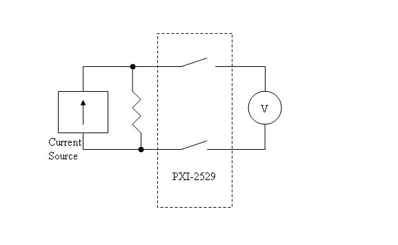
Hi all! I have the PXI-2529 matrix, and I intend to use it this way: I have a set of magnetoresistifs sensors connected via matrix switches to DVMs (see photo). I need a few times (such as 1 - 100 times a day) to change these connections. Here's the question: one of the parameters of the matrix is common minimum and it is 10uA. I want to understand what is the reason for this setting? (is this leak or something else), and what is that means that the matrix will not work if DVM internal resistance will be large enough, and current jet matrix mixers will be less than 10uA?
Hi store,.
To answer your questions, yes the minimum current is very similar to current humidification, this is the current that is needed to systematically knock the junk of the relay to check that it continues to work properly. Using switches OR defines the minimum current as "the current minimum" which can flow reliably through the switch So, while you will probably be able to measure a signal, even if you're not fulfills the minimum requirement, we cannot guarantee behavior of your switch if you operate out of specifications. If you're running the specification current minumum for long periods of time, the resistance of the relay contacts will increase over time, and your relay will eventually become unusable. Essentially, by non-compliant to the specification, you will shorten the life of your relay.
As for your question, "is to say that after a few years of this matrix using the conductive oxide become big enough and I'll lose the connection?" The answer is Yes.
I hope it's a bit more clear, let me know if you still have questions about that though. Have a good!
-
Hi, I work to calculate the internal resistance of an engine. My program to communicate via OPC servers to the PLC.
So what I actually need: when the State of the shared variable diresist is equal to 16 26 or 36... the program must run and do the whole sequence.
I tried with a loop of events on the State of diresist, but the program does not normally (you can order only the structure of the window prior to the event)
So I tried with the while loop as the fixed program, but I'm getting the measure in loop (he does not measure). and if I click on the stop button, the program stops after completing the measure, the second time. (Which is not a solution because I need the values and the graph of the first loop)
Any ideas please?
-
Single-phase controlled Rectifier
Hi all
I am simulating the single-phase controlled rectifier circuit with Multisim 10. But the wave of the oscilloscope was wrong. Can someone help me?
You have a voltmeter with 10 megohms of internal resistance in series with the output so current can flow. Remove the voltmeter and the circuit works.
-
Input/output USB 6008 test failure
OK I am posting this for the third time, but whenever I go back to the home page of the forum, I'm not able to find my post. If by chance I created duplicates than apologies.
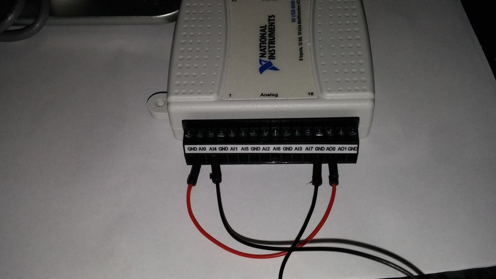
IAM in train to test the USB-6008 case I just got and decided to hang the analog of the analog inputs and see using labview VI.the wiring was done as:
http://i284.Photobucket.com/albums/ll5/bigdawg6/USB%206008%20wiring_zpss2b7hql9.jpg
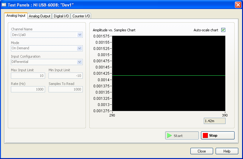
the problem is that the labview VI did nothing, so I go to NI Max and try to see in test panels. But I get 1.4V constantly my same analog input value when I'm changing my analog value:
http://i284.Photobucket.com/albums/ll5/bigdawg6/AIO%20screenshot_zps9beiimbj.PNG
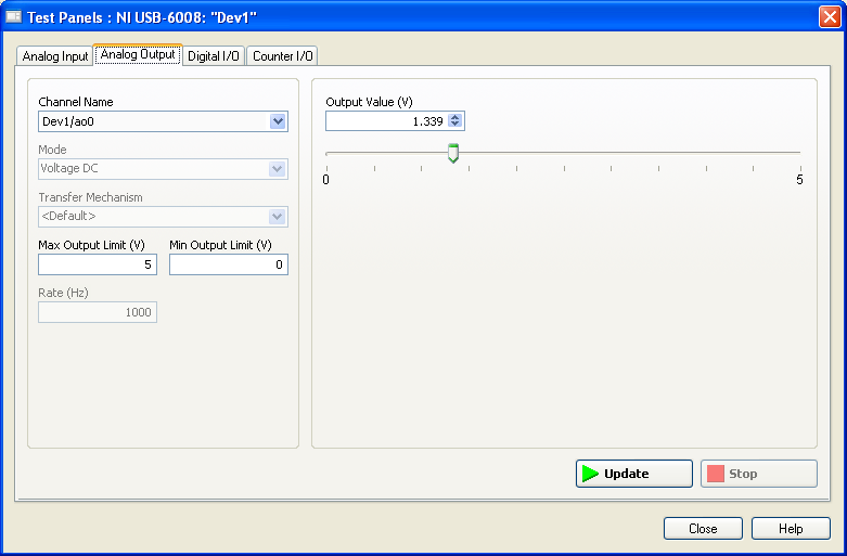
the analog output works very well since I plugged it to my multimeter and I can see the tension that I see on this Panel of test:
http://i284.Photobucket.com/albums/ll5/bigdawg6/AO0%20screenshot_zpsqpei37bw.PNG
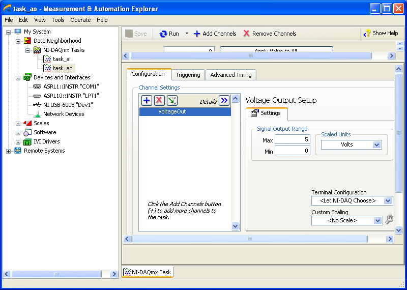
I created an entry/exit of the tasks; screenshots of them are:
http://i284.Photobucket.com/albums/ll5/bigdawg6/task_ao_zpsykmvczew.PNG
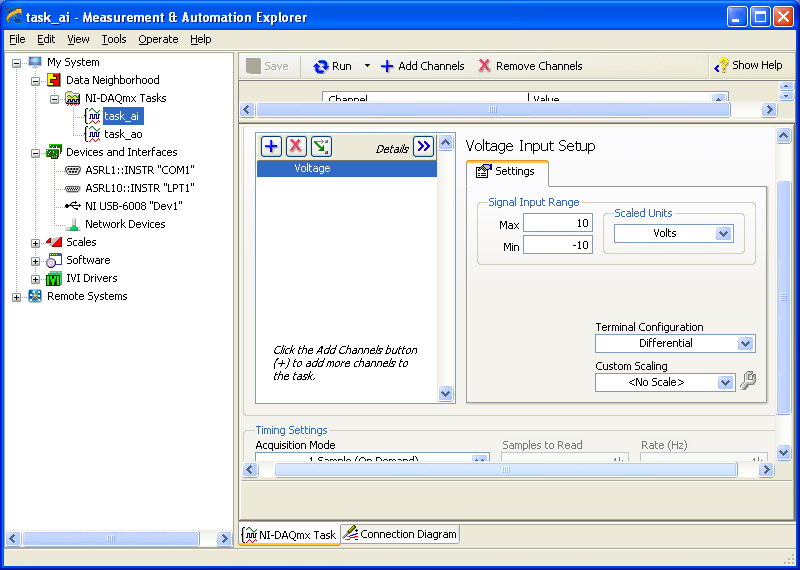
http://i284.Photobucket.com/albums/ll5/bigdawg6/task_ai_zpsix5se9yg.PNG
I am quite frustrated with all this since I'm unable to access my actaul draft. I know that 1.4 V value is from the device itself; as in the manual it says 'internal resistance divider can cause the Terminal to float at about 1.4 V when the analog input terminal is configured as a CSR', but the funny thing is that I use it in differential mode so I don't know what to do and any help is appreciated.
BTW, I did a google search and there are other tutorials onlune who seem to do exactly what I do and they seem to work very well; so I don't know what else to do.
Please don't host images on some odd third-party site. Attach them to your message.
I don't understand what you've done. The 6009 can produce only a signal of CSR in order to set up the differential input makes no sense. If you want to measure something different, try a simple battery.
-
Calibration with NI9237 and NI9944 strain gauge.
Gentlemen.
I have a cDAQ9172 OR with NI9237 and the bridge 1/4 NI 9944. Practically, I'm working on measures of strain gauge issues using a strain than 120 ohms connected to the NI9944 to build the bridge half happening inside of 9237. I have a continuous doubt how is the calibration for the strain gauges. The manual speaks of a shunt resistance which, in the case of NI9944, is already in the system. The manual says that I don't have the shunt resistance external nee. It is clear.
My question is this:
the menu for calibration requires a resistance value that I don't know, I'm leaving in the value proposed by the menu of NOR. The strain gauges takes easily compensate, so I always have to recalibrate the channels in the NI9237. Is this normal? Can a (application to 2.0 V strain gage) voltage of 2.5 [V] generates a continuous drift of the measure?
Strain gauges are: EA-06-125BT-120
Hi cgenco,
Because the NOR-9237 with 9944 uses an internal resistance for shunt calibration, you need not to worry about the value of the shunt resistance. Take a look at the following article that specifies how connections are made. Calibration article will show you the basics behind how to exploit.
Also, since there is a ratiometric measurement, the voltage is 2.5V shouldn't matter as long as your pawn takes care of everything.
-
What is input equivalent circuit of USB 6009 PFI0
The entry USB-6009 PFI0 is the same the analog input circuit stated in manual mode?
I use the PFI0 to trigger a measurement of voltage and it works a lot using a HP function generator.
When I try to drive the low entrance with my circuit looks like there's a pull up resistance to + 5 on the entry of PFI0 terminal.
This entry PFI0 will accept an output of comparitor from 0 to 15 volts with being damaged?Kip
Here is my solution to operate the PFI0 TTL digital input using a CMOS comparator.
I use a 2N4401 npn transistor.
Connect the transmitter to the ground terminal.
Connect the manifold to the PFI0 (there is a pull-up internal resistance to the 6009).
To connect to the Base of a voltage divider that limits in input current and decreases the CMOS voltage to TTL levels.
In my case I'm going to 0 to + 15 so my voltage divider is 4.7 k and 2.2 kohm to fall to 0-5 volts.
It is an Inverter circuit so your sense of trigger will go head on falling edge, or vice versa.
I hope this helps someone.
Kip
-
Hello
I am currently using the connected to a block TBX-68 and Labview 2010 6259. Basically, I'm trying to just use it for a multimeter to get accurate and timely measures, but there is something I don't understand all the examples in Labview.
My program is set up very similar to the "Acq a Sample.vi." I use a wizard DAQ with CSR configuration. When I connect a voltage source to a resistance that is connected to the PIN 68 to the TBX and spindle 67 to the land of the source voltage and the current measurement, I get a reading, however the current changes only as a source of voltage is changed. If I trade on the strength of a higher (or lower) value, the current does not change. I think it has something to do with the resistance of internal shunt within the program, but if I need to measure current with precision to determine an unknown resistance, how can I do this?
Mayy_B,
First of all, you should not use CSR to your measure, you should use NRSE because you don't measure a floating source. More information can be found in this article: http://www.ni.com/white-paper/3344/en
Please note that this will change the wiring on the TBX-68 block and require the negative line go to pin 62. In addition, there is no internal resistance in the 6259, an external shunt resistance must be used. This resistance must be connected between pins 68 and 62. You specify the value of the resistance in the DAQmx create virtual channel vi which is put in place for the current task of Analog Input. This should lead to a current measurement precise.
-
It is current on the analog module USB NI 9263 output voltage limit (+/-10 v)?
It is current on the analog module USB NI 9263 output voltage limit (+/-10 v)? I try to run a current controlled resistance, but cannot get the required current. The servovalved has a parallel internal resistance of 80 ohms and requires 20 my full operation. Ohm's law: (.02 A) * ((80*80) /(80+80) ohms = 4.5 v) Yet, the required voltage, do not move the servo. Outside the material error (continue this by other means), what could be the problem?
Have you checked the Manual?
Page 12 1 says my.
For servo, you really need some kind of amplifier. See if the manufacturer provides the electronic driver for it.
-
Why counter traction task produced low?
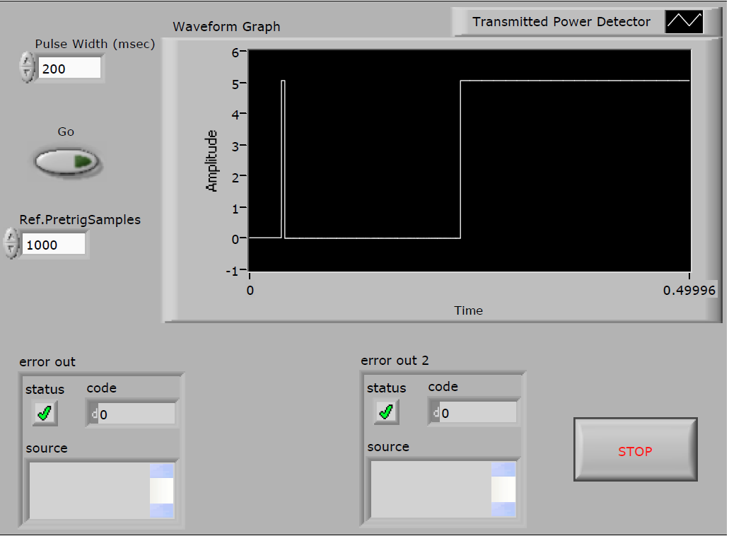
Joined a vi that has a task to analog input, triggered by a meter output. The meter has high idle state and responds to a push button on the front panel by a low pulse of term. This material controls output to the system under test and is also used to trigger the task to HAVE it. The problem is that from the task to HAVE it pulls the output low counter. I use a USB-6341 device, which the meter output is PFI13. When he looking on scope, I saw a few unexpected bahavior of the output of the counter. I put the meter output in analog input and track resulting is displayed on the front panel:
The meter output is low due to the task of GOT it, then at the start of the task of meter output it goes high (resting State) briefly, then makes the desired low pulse this task triggers the AI, returning to high. The problem is that it then goes low when the task to HAVE it is restarted (not visible on the front panel). I need this line to stay high all the time except during the desired pulse. I have found a workaround by the AI of PFI0 of trigger job and routing PFI13 to PFI0 internally, but I do not understand why the version posted here does what he does. A trigger line must be an entrance to a task of GOT it, and begin the task should not affect his State. I thought the task of AI may use the meter so I tried using a different counter but got the same results. Using a trigger to start with no samples before release did not have either no difference.
Richard
Hi Richard,
Digital lines actually have 3 States:
- High output
- Low output
- High impedance (input)
When you use the PFI line for an input trigger, the typical desired state would be high impedance. X series cards use an internal resistance of the drop-down list of ~ 50 kOhm, pulling the line low when it is configured as an input. Engage the task of GOT it, which is to set up the PFI line as input.
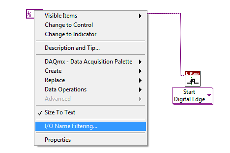
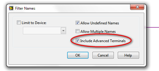
If you want to trigger the analog task on the output of the meter, I suggest to use the internal output of the meter without going through the PFI lines. You need to activate produce terminals via the right-click menu on the Terminal control DAQmx / constant:
In this way, the meter may continue at the exit on the PFI line and the task of the AI don't tent not tri - state PFI line. You don't have to do all the external connections.
Best regards
Maybe you are looking for
-
Problems with the Google account sync on iPhone
running iOS on iPhone 9.3.2 and 10.11.15 El Capitan on MacBook Air. I don't know when it happened, but my info from Google to sync seamlessly across devices, and somewhere along the line, he stopped. I noticed that the notes in the Notes application
-
iPhone freeze Contact Search, does not properly
I saw a few chains with a touch Iphone freeze and wanted to tell my experience to see if anyone has seen similar problems. I have observed since on IOS 8.3 that my contacts are starting to freeze when I get more than 4 characters. The problem seems t
-
RelayState parameter is a full support with ADFS in Windows Server 2012?
We implement Single Sign-On with ADFS. (Service Provider - salesforce.com, identity provider - ADFS). But when authenticate us with ADFS, he is will authenticate successfully, but it will be redirected to the site complete salesforce instead of the m
-
Acer has a similar application like samsung
-
Since windows did a update my video cards are sometimes overwritten at startup
When I turn my computer on my screen, readers will sometimes have the crash livekernelevent and I need to reinstall but isn't that a temporary difficulty because he just started when I started my computer Everything worked great until I rebooted my c