issue 1405 acquisition
Hello
I use an acquisition card NI PCI 1405, camera watec 902 b (RS170 standard).
When I purchase, I have horizontal stripes of noise on the image. These bands are make from the bottom to the top of the image during acquisition. In this case, if I use MAX or my own it. In MAX, I use the rs170 driver. I found the RS170 (1409 and RS170 (1410), but no drivers as RS170 (1405).) It could be related? In addition, the cameras that I use are not in the list of cameras officials nor supported, but since they work with the RS170 standard, I think that there should be no problem. You can find the specification on my cameras here.
Thank you.
Hi Yoasis,
Do you use cables BNC shielded 75 Ohm? Don't you see the same model on all cameras? The noise moves within the same image, or is it a constant line? Also, since you mentioned "cameras", you have several cards 1405 as well? If so, do you see the same noise in each of them?
Thank you and have a nice day.
Esmail Hamdan | Engineering applications. National Instruments
Tags: NI Hardware
Similar Questions
-
Possible battery issue with my Satellite 1405-s151
I have a satellite 1405-s151. Since July it does not start. When I turn it on the green light is on but nothing happens. However, it is sometimes begins with a Cmos checksum bad error (ROM) or.
someone told me it might be a dead cmos battery.what you think about this? I live in Senegal and there is no center of toshiba
Hello
I don't think that there is a problem with the CMOS battery. If it is defective or has a low voltage, the machine will give this error, BUT it will never have a problem starting up because of this. A bad battery will make the system lost track of time and date and possibly some settings that you could make in the Setup program, but when the unit starts up and displays the error message (you must press the F1 key to continue) the default settings will be defined and they are good enough to make the system bootable. I suggest you to remove any material that you may have added to the unit (memory, PC cards and so on), and then try again. If it still does not work then I think your machine is faulty and need service.
Best regards
Tom -
The confocal issue custom with PCI-based 1409 acquisition
We use a PCI-1409 to acquire a video from a custom confocal system flow and high definition image. We use the junction box BNC to send in luminance, hsync and vsync in the PhotoMultiplierTube and our custom control box.
Because of the way we scan using Resonators, we have two corrections that we hold in the video stream and that you are not sure if this is possible at the level of the camera, i.e., place the code in the .icd file, we did, or if it is something that must be completed in LabView. Any help would be greatly appreciated.
One distortion: Acquire us information of luminance in both sense of sweep. Our image is one where all other lines is reversed. Is it possible to invert all other lines and register? Now double us the apparent width of the image and then having to crop the image twice, reverse a stack of image and then interleave.
Two distortion: mirrors scanning speed varies sinusoidally and stretching that occurs on the edges so there. How would we go about filtering the stream in order to fix this? I guess it's something that should be done in LabView as pixel clock is fixed.
The file .icd, we have changed the default settings to get a stable picture with the two aforementioned distortions is attached.
-sb
I would just use a single CIM file with odd and even lines. For the preview, use deinterlace or extract to remove the odd lines. For full images, make the post processing later.
Bruce
-
Acquisition of fast mode for 9214 with VB6
Hello
I have a VB6 application that acquires data from a device to measure temperature NI 9214. The unit has two modes of acquisition, large (default) precision and high speed. With the help of MAX I can see that these modes both work in a test Panel. However I can't see how to change the mode at high speed by program in VB6. I am generation and execution in VB6 in DevStudio 2008 on a virtual Windows XP machine (host is Windows 7) using 14.2 DAQmx. Also running the compiled executable directly on Windows 7 without problem. I just want to change the mode of fast sampling (up to 100 samples/s for a single channel), while the default precision is only 1 sample/s. looking at transients of the order of 0.01 s over a period of 2 minutes.
Can anyone help with this?
Kind regards
Chris
I found a solution that I posted a separate issue here. Thank you for all your help.
-
frequency DAQ USB issue (6211)
Hello
I'm a newbie when it comes to NOR and data acquisition. I bought a NI USB 6211 and connected a resolver with 400 Hz and ai1, ai2 (CSR) (sine and cosine signals). I also have the reference of the power supply connected to ai3 (differential) of signals. Pockets of tension give a +/-2.5 Volts from all sources input signal.
The problem is that the signal moves to the right. She moves uniformly for all signals.
Now, I wonder is it possible to synchronize the input signal so that it moves? or what I need to resolve this issue programmatically? I'm programming in C with standard DAQmx drivers (v15.1). But I saw the same problem with Labview and Measurement Studio.
Thanks in advance for your suggestions.
Kind regards
Gerhard
I guess I just find the answer to my question here:
http://forums.NI.com/T5/LabVIEW/DAQ-Assistant-can-t-lock-the-signals/m-p/1332484#M542285
I guess I have to ask in the forum section of C++ for an example of a software lock.
Kind regards
Gerhard
-
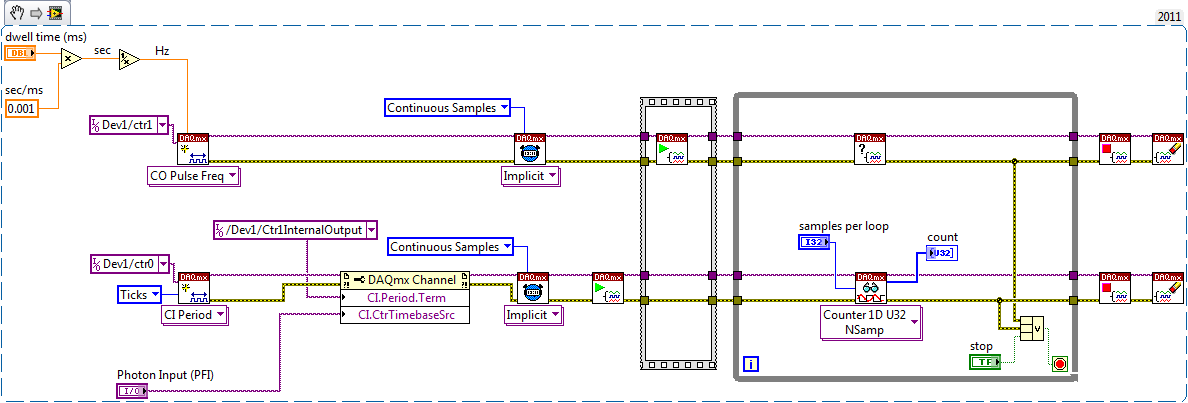
Helps the acquisition of photon counter data using LabView 12
Hey all,.
Student graduate Chemistry here new to LabView and are looking for some help moving in the right direction. I'm looking for help with connecting my meter to 12 LabView for data acquisition of trace-fluorescence photon PerkinElmer SPCM-AQR-14 (now owned by Excelitas Technologies). I just want to be able to acquire number of photon counts vs. time. Currently, I installed a PCI-6601 and use a BNC-2121 to connect the BNC of the sensor output. The detector has a pulse output digital TTL with 30 ns pulse width, and by contacting technical support on this issue, I was told that this pulse width was too short to always detected by the 6601, but can still go ahead and give it a try. Basically, if everyone is familiar with how to start with this configuration, ANY help would be greatly appreciated. As I said I'm all new to LabView and am currently spend all my spare time reading manuals and help files.
Please let me know if you need any kind of information to make me understand what I'm doing.
I would say something like this:
A measurement period the registry account out of the entrance of the samples as well as gives the meter. You will basically measure the 'period' of your sample clock fixed regarding ticks of the external photon signal.
According to the downtime, you may need to re-read several samples per loop so that the software can keep up with the incoming data. Also, the first sample is not useful because it represents the County between the software from the task of entry of the meter and the first clock signal - you should disregard/erase the first sample (or if you want you can set up a trigger to begin arms).
To do the same thing by using an edge County task would require using both the sample clock AND a counter reset signal - this not is not supported on 6601/6602 (even if it would be possible to set it up that way on a device of STC - 3 as a series of X).
Best regards
-
acquisition of simultaneous generation of 6555
Hi, we strive to get data in and out of a map 6555 to/from our associate DEGREE, which is connected to the map of 6555 via the provided wiring and LabView with the manual VI tool which allows to control the map sample data, the wiring is correct (confirmed the scope).
However, when we run our automated program that is supposed to load our data files and send them out, we don't see no signal at all on the same PIN that we led with manual tool of VI.
How our hardware guy wired the Board upward is kind of arbitrary (some channels are entered, some are out and not in a particular order or organization).
As a beta test, we start with channels mapped to the acquisition of DIO0-DIO15, and DIO16 mapped to the generation. There is an HWS file, I created and which contains the data flow for DIO16, and then we want to save DIO0-DIO15 while DIO16 sends data.
However, we do not see the data coming out the wire again.
Two main issues:
(1) what string values should we be turning to niHSDIO_AssignDynamicChannels() to put in place the channel like that assignment?
(2) should we padd strings in the data file that we send to niHSDIO_WriteNamedWaveformU32?
I was wondering if the data we are trying to send to DIO16 maybe DIO0 or something.
Thank you.
Ed
Since you're using the U32 write, it means that writing VI expects an unsigned integer of 32 bits, with each bit associated with an output of the 6555.
So for output to line 16, you could Pad the 16-bit integer. (Basically of output hex 0 0001 0000 x corresponding to 1-bit followed by 16 zeros).
-
USBTMC Data Acquisition Device Firmware
Hello
I'm trying to develop a simple data acquisition equipment which can interface with Labview using USBTMC Protocol. The rest of the sheet USBTMC and USBTMC-USB488, I have implemented the code to treat endpoints in bulk-Out with all the message ID. However, I am a little confused on how NI-VISA actually interracts with a device. When a command viWrite or viRead is given, what are the specific messages are sent to the device on which endpoints, and what is the expected response of the device? What would the classic process to acquire large quanties of data from a USBTMC device? If you can clear all this for me, it would be greatly appreciated!
Thank you
Mike
When the host issues viWrite call, the header USBTMC_BULKOUT of 12 bytes followed by your channel SCPI is sent to the endpoint of your firmware BULKOUT. In this case, USBTMC_BULKOUT header contains MsgID = 1.
When the host issues appeal of viRead, USBTMC_BULKOUT of 12-byte header must be sent to ask for playback to the BULKOUT endpoint. In this case the MsgID = 2 and the length is only 12 bytes of all. Then your firmware, if a response string is ready, must set the header USBTMC_BULKIN followed by the answer of the SCPI endpoint to send BOULKIN.
viWrite generates a transaction BULKOUT and viRead generates a transaction BULKOUT more BOULKIN transaction.
example:
viWrite ("* IDN?") \n') - generates a transaction bulkout in the form of bytes [12 + 6 + 2]. (the last 2 bytes are padding to align the 4 bytes)
Correcponding viRead () - generates a bulkout in the form of bytes [12], then the firmware fixed Boulkin data [12 + response + padding].
Makoto
-
Configuration of the two of the same model data acquisition
Hello, community of NOR.
I'm an intern in mechanical engineering with experience in base with LabVIEW.
I would like to speak to OR directly on this issue, but I don't have a service contract and my company wants me to understand this before you buy LabVIEW.
I hope that someone has experience about my question, and I would be very happy to help.
We intend on purchasing an expansion card for our acquisition of data (OMB-USB-2416), but unfortunately it is offline and no custom would not happen in time.
So, I need LabVIEW to read voltage HAVE two of the same model of data acquisition, which would amount to about 30 channels.
Is this possible with LabVIEW?
Thank you.
Measurement computing says that the "physical channels" dropdown list is automatically filled in once both devices are configured.
-
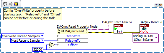
Question about the Acquisition continues through NOR-DAQmx
I'm a bit new to NIDAQmx methodology and I was wondering if someone could could give me some advice on accelerating certain measures of tension that I do with a case of DAQ NI USB-6363.
I have a python script that controls and takes measurements with a few pieces of equipment of laboratory by GPIB and also takes measurements in the area of DAQ OR DAQmx via (I use a library wrapper called pylibdaqmx that interfaces with the libraries C native). As I do with the data acquisition unit is 32 k samples at 2 MHz with a differential pair to AI0. An example of code that performs this operation is:
from nidaqmx import AnalogInputTask

# set up task & input channeltask = AnalogInputTask()
task.create_voltage_channel(phys_channel='Dev1/ai0', terminal='diff',       min_val=0., max_val=5.)
task.configure_timing_sample_clock(rate=2e6, sample_mode='finite',
      samples_per_channel=32000)

for i in range(number_of_loops):  < ... set up/adjust instruments ... >  task.start()  # returns an array of 32k float64 samples  # (same as DAQmxReadAnalogF64 in the C API)  data = task.read(32000)  task.stop()  < ... process data ... >

# clear task, release resourcestask.clear()del task< ... etc ... >
The code works fine and I can all the 32 k spot samples, but if I want to repeat this step several times in a loop, I start and stop the job every time, which takes some time and is really slow down my overall measure.
I thought that maybe there is a way to speed up by configuring the task for continuous sample mode and just read from the channel when I want the data, but when I configure the sample for the continuous mode clock and you issue the command of reading, NOR-DAQmx gives me an error saying that the samples are no longer available , and I need to slow the rate of acquisition or increase the size of the buffer. (I'm guessing the API wants to shoot the first 32 k samples in the buffer zone, but they have already been replaced at the time wherever I can playback control).
What I wonder is: How can I configure the task to make the box DAQ acquire samples continuously, but give me only the last 32 samples buffer on demand k? Looks like I'm missing something basic here, maybe some kind of trigger that I need to put in place before reading? It doesn't seem like it should be hard to do, but as I said, I'm kinda a newbie to this.
I understand the implementation of python that I use is not something that is supported by NEITHER, but if someone could give me some examples of how to perform a measure like this in LabView or C (or any other ideas you have to accelerate such action), I can test in these environments and to implement on my own with python.
Thanks in advance!
Toki
This is something I do a bit, but I can only describe how I would do it in LabVIEW - I'm no help on the details of the C function prototypes or the python wrapper.
In LabVIEW, there are accessed via the 'DAQmx Read property node' properties that help to implement. One is the Mode "crush" which I'm sure must be set before performing the operation. The other pair is known as "RelativeTo" and "Offset" and they allow you to specify what part of the CQI data buffer to read data from. If you the config to "RelativeTo" = 'most recent sample' and 'Offset' =-32000, then whenever you read 32000 samples, they are the very latest 32000 which are already available in the buffer of data acq. Between the readings, the task is free to overwrite the old data indefinitely.
Note that you will need to do this continuous sampling mode and that you can explicitly set a buffer size smaller than the default which will choose DAQmx based on your fast sampling rate.
An excerpt from LV 2010:
-Kevin P
-
Multichannel data acquisition and 2D signals
Hello
[Use of labview 2011 license academic with NI9234 and cDAQ-9178].
I'm trying to read, display and record the signals from two isotronic accelerometers and a microphone at the same time for future signal analysis (FFT, etc.). I wish to display data of vibration and noise signals in real-time at 44100 Hz sampling frequency and display a waveform of final sampling, which takes about 40 years. I would like to then write the data to a file.
The associated block diagram, attached vi. I could view real-time each accelerometer and sound using iterations of the loop and split the signal. Unfortunately I record three channels of data in a table unique 1 d-wave form. It seems that the data is saved as iteration1 (ch0) .iteration1 (ch1) .iteration1 (ch2) .iteration2 (ch0) .iteration2 (ch1)... and so on.
Although I could show all three signals separately in the waveform graph, but I prefer these data to save as table 2D-waveform (each channel in a separate column).
I believe that this issue has been raised here (http://ni.lithium.com/t5/LabVIEW/Concatenate-2D-data/td-p/873409) unfortunately no solution has been proposed. How can I record the signals of data acquisition in 2D waveform?
Thank you.
I think to represent vi attached a solution architecture producer consumer for the problem mentioned above. Just thought I'd share to those who can live a similar situation that I had been faced.
-
Here is my sensor
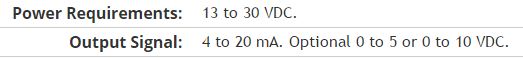
Pressure sensorHere's the DAQ data sheet:
Here are my issues:
First of all I don't know what is LO and HI exactly in the DAQ 9219 material.
Second, I don't know what pin code I should connect the DAQ sensor signal wire. PIN 4 or 5 pin? The sensor has three pins, and I guess I should connect the other two wires to the power supply.
Thirdly how to calibrate the sensor. In labview choose voltage in the wizard?I'm pretty new in this acquisition of data and I need your help.
Thank you
Hi SilasIII,
Hmm well 3 sons are probably on the ground, the power and the return signal. The datasheet for the sensor says:
First of all, you need to know which model you have (4-20mA, 0 - 5V or 0-10VDC). HI refers to the return signal, LO essentially means the land of the food that feeds the sensor. Then, you must get the 13-30 VDC supply. I don't think this should be too complicated and can be a simple wall DC power. You can learn how to create a custom in DAQmx scale. I hope that this is a starting point.
Kind regards
Eric
-
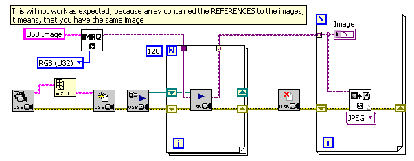
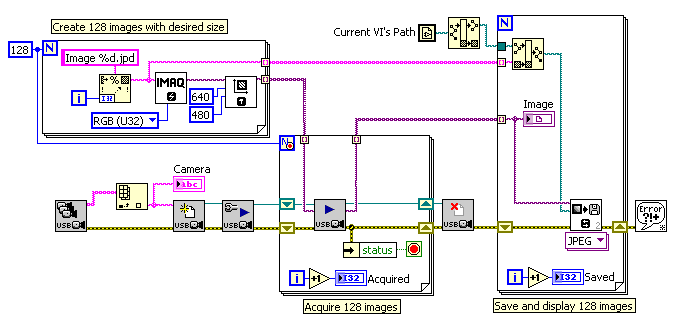
I have image acquisition via a USB camera to a 12 speed. The problem I have is to save these images. If I save these images while acquiring data, the program cannot keep up at this rate. I need a way to get images to 120 and then save them once the acquisition completed. I tried to build a table, but it doesn't seem to work (the issue is when I have the array index, I do not get out images). Any suggestions on this approach or maybe a different approach to achieve this.
Thank you.
Hey, gene,
Guess IMAQ Vision + IMAQ USB was used.
The typical error is grouping table of images IMAQ. Do not forget, that the IMAQ image passed as reference, not the image itself. This means, the following code will not work as you expect:
What you need is the following. You must create your buffers before acquisition, then acquire each image in the own buffer:
It will be useful,
Andrey.
-
Save all data acquired by data acquisition
Hi all
I have a problem when I tried to record all the data acquired by the DAQ card. My DAQ is NEITHER 6259, and the version of Labview is 2009.
Basically, what I do use several channels to get different point tensions, then subtract values of both channels (V + and V-) to get the value of the voltage between two points. In my vi, the method of sampling is continuous and the rate is 100 KHz, DAQmx reading is within a while loop and the number of samples per channel is set at 100. After each execution of the loop, I'd get 100 data. I just use the format in the file to write the data to a .txt file. It seems from that 1 loop only the last data is saved instead of 100. Previously, I have averaged 100 data inside the acquisition loop for a given, so the write function is OK, but it really slows the program. So I want to write all the raw data in a txt file so later I can treat in Matlab. Is there a way to do this? Thank you very much.
The seal is the my vi for 2-channel voltage and current source code control under vi. I am new to Labview so the issue really bugs me even after I read a few similar topics in the forum.
Kind regards
Audrey
When you set the number of samples per channel-1, it will read all the values available in the buffer. A good benchmark would be to read about 1/10th of your sampling rate. That is to say. If you read at 100 Hz, read 10 samples per channel.
Best,
-
acquisition of data high-speed and simultaneous sampling
I'm quite familiar with the coding for NOR-DAQ boards in Labview. What worries me with labview, is that each tick is about milliseconds. I intend to retrieve the data simultaneously from 32 channels at 2 MS/s/chan using SMU 6368 s. Wouldn't not possible to enter data, on average 20 to 50 samples to get a unique value, perform simple algebraic manipulations on it and send it to the PC / software to approximately tens of kHz? We already have labview code to perform similar tasks, but it is quite slow and limiting the rate of experience. I said that Simulink is slightly better than Labview in this regard, but suffers a poor user interface and that if something C/C++ offers the ability to perform at high speeds with the same cards OR data acquisition. Could someone advise me please on this issue?
You can use your PC! You can use a PCI/PCI-e card as the interface to your computer and it should work perfectly. Take a look at these pages (http://sine.ni.com/nips/cds/view/p/lang/en/nid/10389) for more information.
Maybe you are looking for
-
synchronization between Outlook 2016 and iPhone & iPad
My 6s iPhone and iPad 2 sync properly with iCloud. I can't 2016 Outlook on my PC of 10 Windows to synchronize. I downloaded iCloud for windows. Any suggestions? Thank you Tom G.
-
OfficeJet 6600: upgrade of Windows post 10
After upgrade Windows 10 on 29/07/2015, my 6600 Officejet continues to work and print. but when I click on my desktop icon to view ink levels or that scan a page comes up saying install new printer. In the control panel Officejet 6600 is indicated as
-
In the Start Menu, the Documents link no longer works
Original title: Link Documents In the Start Menu, the Documents link no longer works. How should I do? Thank you.
-
Error 1603 installation when you install Sage Instant accounts 2011
Original title: 1603 Installation error I am trying to install Sage Instant accounts 2011 on my lap top to Windows Vista. I get an error 1603 database and stops the installation. How can I solve this error? I tried my temporary folders of compensatio
-
WIN8 Apps (including Office 2013/365) crash when printing to Canon 8350CDn
Hi - I tried to find info about this problem on the Forum Office 365, but they sent me here... I have a Canon 8350CDn... When I try to print to this printer from these apps, Office 2013, Notepad, Wordpad immediately crash. Other applications, includi