J1939 or CANOpen
Hello dear colleagues,
I have to develop a SW for CompactRIO communicate with a controller on the CAN.
My question: which protocol, CanOpen and J1939 is easier and faster to implement the example? I am in great haste and need to implement communication for my prototype as soon as possible. What is your recommendations? I use CompactRIO.
Thank you in advance for quick reactions!
Regarding
Petr P.
Hi Peter,
We have an example of reference for j1939 but no driver official. That said, there is a custom device veristand, which might make it easier if you are familiar with veristand.
If you have material canopen, canopen API and examples will be probably faster and are supported. However, we have only one material for the cRIO canopen, the 9881.
Tags: NI Products
Similar Questions
-
What source address should the NI9862 module CAN be used to send messages j1939?
I am developing an application that will write and read on vehicle ECU road. I CAN NI9862 module and drivers XNET. I can read an ECU data. I can write a CAN bus frames but the ECU under test does not appear to read the message. I don't get any acknowledgement of bit type and the SHIELD in question (a dashboard) does not change its messages in anyway, nor change the gauges or witnesses.
Complicating this is the fact that the ecu is 'Brand X' and it is PGNs belong to someone. I tried to send the message of inquiry PGN (PGN59904) but get no response from the ECU. I use the 255 (global) as my source address.
Is there a source given for the NI9862 in J1939 address?
Thank you
There is no specific source for the NI9862 address. It can be used to simulate one of the 256 available addresses. If you try to simulate a test off-board tool, usually has an address of 0xFA.
I'm afraid that if you do not know the PGNs he expects or addresses that it expects to see, you will have great difficulty to operate.
Good luck
Bob Young
-
Hello
I'm trying to implement a communication between a motor current continuous (not OR) and LabVIEW.
PC (LabVIEW)-> NOR-8472 (USB - CAN)-> DC MOTOR (CanOPEN)
This is my setup
I tried this example, the example of CanOPEN SDO for USB CANhttps://decibel.NI.com/content/docs/doc-
But I am not able to write anything... You guys have advice for beginners?
My second question, when I have a functional communication between LabVIEW and motor continuous.
How can I control using LAbVIEW?
I just need you to order:
-Start
-Stop
-ReverseThank you
andechrandechr wrote:
I'm not able to save this example, every time that his end he down and restart I have to change the interface, index, etc...
When I tried to build my own I cannot find pallets for SDO READ, WRITE SDO etc.
You set the default control values and save the VI? Do you have to set the values of control at startup?
This example looks like it uses a modified version of this library.
http://www.NI.com/example/30873/en/
I've never used this library and have no idea how it may have changed. If you have any questions on this example, you'll probably want to contact the developer, they don't have give a lot of information there.
-
I talk with a few Parker SSD drives using CANopen. When I was talking only to a single player (690 +), I was able to do everything with PDP and everything worked fine. Using PDO I could start to LABView, then turn on the player and the program would begin to speak without problem. But now I'm talking to another drive (590 +) at the same time. I decided to use SDO when you talk with the two SSDS instead of the PDP because it seemed easier to read/write data. I need to start LV before SSD drives to ensure that certain relays are properly defined.
So I have a few questions.
The first problem is that as soon as I start my program of LV, I get errors SDO because SSDS are not turned on and running. So I try to find a way for LV search different SSD readers before trying to send/receive their. Some how the PDO is there but not of the SDO.
Another problem is in talks with both drives at the same time, I think I mess up the configuration somehow. CANopen vi example only shows how talking with 1 device at once, is there examples on how to install talking with 2 devices? I can run SDOread.vi on each device, so I know that I have the communication. I left the default configuration values in the SDOcreate.vi. I tried looking for info on the COB ID server and customer ID s/n settings, but I still found nothing.
Thanks for any help...
Well, I went back to the use of the PDO. There was a problem with some of the SDO addresses on one of the units, so I had no choice.
-
I have two boxes CAN1 and CAN0 hooked to a junction box
1 ea, CAN Breakout Box - Junction 14-Port with power and termination box
2 bis, NI USB-8473 -1-Port high-speed CAN, USB Interface
I have LavView 2013 worm 13.0f2 (32 bit)
I use 'c' library: C:\Program Files (x 86) \National Instruments\NI - CAN\MS Visual C\nicanmsc.lib
who has a 'creation Date' 13/03/2012-15:35
I think the 2.7.4 version number but I don't know where to find this number.
I have Windows 7I want to send a J1939 Messages on CAN1 with LabView
(I have a job.)I would like to receive Messages from the j1939 on CAN0 using MS .c program
(I have work for BAM messages, but not for RTS/CTS messages
< 240="">I can't get non-BAM RTS CTS messages to work.
I get the RTS, but I don't know how to set up a BOX to be associated
'BB' DA (Destination address).
I also send the CTS with ncWrite but I always get a
"Connection Abort is.I think I need to configure the two cans with an address.
I wish
CAN1 sending CAN be 'AA' (it would also receive the message CTS)
and
CAN0 reception CAN be 'BB' (this would also send the message CTS)Here's what I'm trying:
I am trying to send a message of J1939 RTS CAN1:
1CC2BBAA
where
1 - 0001 1100
PAPP DETERIORATED
aaOr rrDP
ddFi IPI
7 -low priority
. -SOF will have the value 1 in the LabView by ORing program 0x20000000.. C2 -194 - PF
Group of settings label: report of Performance Monitor
PGN Desc. :
Specify the legislative requirements of OBD
manufacturers must control all emissions and
SELF-DIAGNOSIS of the components system throughout to wait
life of the vehicle..... BB -187 - PS / DA
A 'BB' address I did up to destination.
I would like to CAN0 be configured with this address
but I don't know how I should do this?...... AA -170 - SA
A source address 'AA' I did.
I wish that CAN1 be configured with this address
but I don't know how I should do this?I put in place of the test data
| LS MS | LS MS | LSD MSD | LS MS | LS MS |
| F4 01 | 0A 00 | 8 D F8 02 | 14 00 | 0A 00 |who is for
----------- ------- ----------------------------------------------
SPN
Position
in
PGN SPN SPN Description
----------- ------- ----------------------------------------------
01-02 3048 engine cycles counter
03-04 3049 control of the Conditions encountered
05-06, 7.6 3066 SPN of the Applicable System Monitor
08-09 3067 numerator applicable system monitor
10-11 3068 denominator applicable system monitor
----------- ------- ----------------------------------------------If you reverse the LSD and the MSD around you get this:
(I just do these numbers for testing.)| LS MS | MS LS | MSD LSD | MS LS | MS LS |
| F4 01 | 0A 00 | F8 02 8 D | 00 14 | 0A 00 |01 F4 -online 500
Engine ignition cycles counter0a 00 => 10
Terms of OBD monitoring
Met
F8 8 02
1111 1000 0000 0010 1000 1101
.... . 000 0000 0010 1000 1101 "."-unused bits set to 1
0 0 0 2 8 D
00028D -online 653
SPN of the Applicable System Monitor
Injector cylinder #03
00 14 => 20
Applicable system monitor
Numerator
0a 00 => 10
Applicable system monitor
DenominatorI used the example LabView .vi at the following address to send the message:
http://www.NI.com/example/31215/en/
Then click on the link to the right "J1939 Transport Protocol"
That you will get this zip file: "transport_protocol_8.6_2v.zip".Inside of this zip file
«...\transport_protocol_8.6_v1.1\transport_protocol_8.6\J1939 Multi Frame\Examples\NI packet CAN fit OR Example\J1939 CAN fit Example.vi"This load in LabView
I used the following example of 'C' to read the message:
C:\Users\Public\Documents\National Instruments\NI-CAN\Examples\MS Visual C\Frame API examples\CAN Receive\CAN Receive.cI wrote a 'c' code to test the RTS message
and then
do a ncWrite to send a CTS.
He doesn't work and I get "Connection Abort Message"I don't know what I'm doing wrong.
Here is the output of debugging with my comments (CMT :)
-------------------------------------------------------------------
CMT: EC message with 0 x 02000000 ORed SOF in LabVIEW
CMT: and the priority changed shape 05:53 (110)
CMT: do 38
CMT: 0011 1000
CMT: PAPP DETERIORATED
CMT: aaOr rrDP
CMT: ddFi IPI
CMT: 1 priority 10-6CMT: EC - Transport Protocol - connection Mgmt.
CMT: BB - DA (Destination address)
CMT: AA - SA (Source address)SAM: 10-16, RTS Message
CMT: 0 b 00-11 my size
CMT: 02 NumPackets
CMT: MaxNumPackets FF-255
CMT:-00C2BB PGN BB C2 00
CMT:
CMT:
CMT:c 10:32:51.548 38ECBBAA CAN data frame C2 of BB FF 02 00 00 0b 08:10
iMessageDataSize =: 0:
RTS beginning: 10: (10 - RTS)
RTS my size: 000 b: (11)
RTS Num Pack: 02: (2)
RTS Max Num Pack: FF: (255)
RTS PGN: 00C2BB:CMT: Here's the CTS to send the data that I created to send with ncWrite
CMT: 11 - fixed 17, message EC PGN 60416
CMT: 02 - maximum number of packets that can be sent
CMT: 01 - next to use sequence number
CMT: FF FF - reserved. Filled with FFs
CMT: BB C2 00 - 00C2BB PGN.... In SendCTS...
iBAMRTSCAMPgn =: 00C2BB:/Ucdata CTS [0] =: 11:
CTS /ucdata [1] =: 02:
CTS /ucdata [2] =: 01:
CTS /ucdata [3] =: FF:
CTS /ucdata [4] =: FF:
CTS /ucdata [5] =: BB:
CTS /ucdata [6] =: C2:
CTS /ucdata [7] =: 00:ActualDataSize =: 1:
CMT: I have more a data message "EB00" or "38EBBBAA" but I
CMT: get '38ECBBAA' with 'FF' in the 1 byte of data, which means
CMT: "Connection Abort Message.iPri =: 6:
iEdpDp =: 0:
iPf =: EC:
iPs =: BB:
iGe =: 00:
Fnpi =: EC00:
iSa =: AA:
c 10:32:52.799 38ECBBAA CAN data frame 8: FF FF FF FF FF BB C2 00
iMessageDataSize =: 0:I've corrected the program.
It was the following statement:
was as follows:
Status =
() ncWrite
gNetIntfObjhRx,
oCFSend.DataLength,
(void *) & oCFSend
);should be this:
Status =
() ncWrite
gNetIntfObjhRx,
sizeof (oCFSend),
(void *) & oCFSend
); -
Industrial communications for CANopen - interface create error
Hello
I am trying to run a few basic examples, I found with the finder example in communication industrial directory - NOR - for CANopen-> cRio-> FPGA bitfiles-> CANopen_cRio_heartbeat.vi.
But the block 'create an Interface' gives me the error 2147136667.
I work with with module NI 9881 cRio. The module is connected to the robot from Festo.
You please any idea what can cause this error?
The text of says error:
Possible reasons:
You try to start an interface that is missing the bus for the transceiver power. Some physical layers on the material OR CANopen are fed internally, but others require an external power supply so that the port to operate. This error occurs when starting an interface on the equipment that requires an external power supply when no power is detected. Power supply right to your transceiver. Refer to the material of the NOR-Industrial communication CANopen Book for CANopen help for more information.
See you soon
Ivo
Hello T.t,
The 9881 must be fed outdoors. You can do with a CAN of junction box or with a Câble CAN.
Concerning
-
the value node id and baud rate by lss (CANOpen)
Hello
for a research project, we try to use 2 volume CAN flow sensors (http://www.hydrotechnik.com/english/QT106_DSEN.pdf) . For use in our network CAN I first set up the node id and the baudrate of each of them. The manufacturer told me to do it via the put layer Service (LSS). (How) I can do using Labview?
I can use one of the following cards, NEITHER CAN: NI PCI-CAN/2 and NOR-PCI-8512.
Thanks for the tips.
Greetings,
Thomas
Unfortunately, none of your interfaces are compatible with CANopen. You will need a PCI-8531.
The flow rate in baud rate and node id can be configured easily with the library OR industrial for CANopen communication .
-
Support for LabVIEW 2014 and CanOPEN cRIO-9067
Hello
We have NEITHER 9881 CANOpen communication module and cRIO-9067.
According to the NI 9881 product description page the module should work with cRIO-9067. However, does not support the latest NOR-Industrial Communications for CANopen 1.0.3 2014 LabVIEW and NI RIO 14.0. This means that we cannot use cRIO-9067, can we? If so, when the next version of the pilot will be available? It will work with the cRIO-9030?
Thank you in advance,
Nikita.
Hi Nikita,
I wanted to let you know that support for the cRIO-9067 is available: http://www.ni.com/download/ni-industrial-communications-for-canopen-14.5/5234/en/
Thank you!
-
I neeed an example of a device custom for brushless control throught Canopen communication
Hello
I want to do a custom for brushless control throught communication Canopen device, I don't know if I could find an example to start
I have the following equipment:
-Maxon Brushless Motors
-NI PXI 8135 RT controller
I have labview 2012 and 2012 veristand
Thanks for any help
Hi Mohamed,
It's Vincent of National Instruments. We will discuss that off-line.
What we provide, it is unlikely that we could provide something that is exactly directly to your EPOS readers.
CANOpen is a standard and we can provide Custom-device for CANOpen. Based in this Custom device, you configure it for your needs.
Concerning
Vincent
-
What do the two LEDS at the top of the NI 9881 CANopen mean?
I have looked through the documentation for the 9881 NI, but have not found any mention of the significance of the two LEDs. Anyone know what they mean?
Please see the Handbook of material found here XNET:
http://www.NI.com/PDF/manuals/372840c.PDF
See page 3-16
NOTE: XNET means the underlying driver components used by CANopen.
-
CRIO 9853: Why the mask is required to send and receive extended frame CAN (J1939)?
I develop application RT who communicate with device of CAN frames extended through CRIO and 9853 CAN module with J1939 Protocol.
I look at Protocol J1939 example of reference to help me in my project.
Everything works fine, but I want to know why when I use the 9853 Module I need to use the bitmask (AND 0x1FFFFFFF to READ and OR write 0x20000000)
As you can see on the example of OR... (to WRITE)
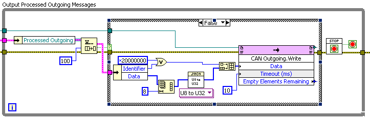
Therefore, use both mask the good CAN Frame ID on the network?
He's not blok me... but I would like to understand why I need to add this code...
Hope someone will have the answer.
Roman
Playback uses the 30 bit to indicate whether the ID is standard or extended. Otherwise, if you have received ID 0x0000000A, you don't know if it was std or extended. For higher numbers (> 11 bit), it's obvious, but the flag is set, without worrying if you don't need several branches.
-
CANopen Close VI gel when closing an ODS object
CANopen Close.vi will not stop and is frozen when a SDO object is closed.
I create an interface object, then an ODS object, read the SDO object and then close the ODS object, then the object of the interface.
Any ideas?
I decided to give up this aid on the SDO and simply close the interface. The VI will close all the objects associated with this stage of the interface.
-
Cannot create the CANopen interface
I am trying to communicate to one CAN open the device using the NI PCI-8512 BOX / Board HS. This vi accepts a string interface ID: 'CAN2' and baud rate: '50000 '. I run the VI and it gives me an error code:-1074388957 Source: Create.vi Interface CANopen
I opened the MAX and the port of CAN2 exists and I can open the monitor and see the heartbeat messages. I don't know how to resolve this error at this stage.
Can anyone help?
N8D11,
If you look at product compatibility OR CAN and array of features, you'll notice the reference to the compatibility of NOR-XNET with CANopen. It indicates that the compatibility OR XNET library is required. This is because CANopen is based on the NI-CAN driver, while your device is designed to use NOR-XNET. The article of the Migration of Applications NI-CAN for NOR-XNET DevZone explains the problem in detail. You will need to rerun setup of NOR-XNET and be sure to select the option for the compatibility OR XNET library.
-
How to implement Canopen on FPGA to run the engine using NOR-9881?
Dear,
Your support will be highly appreciated,
There is only one available for NOR-9881 example.
Please note that the following materials were properly connected:
cRIO-9024, cRIO-9113, OR-9881 and motor Nanotec (SMCI36 against L2818L0604-T5X5), the following
sites Web shows the engine Nanotec in details:
http://us.Nanotec.com/products/660-L28-linear-actuators-with-trapezoid-spindle/
http://us.Nanotec.com/products/1041-SMCI36-stepper-motor-and-BLDC-motor-position ing-control /
The main problem is how to configure the inputs and outputs, where, in most examples, the entry and exit have been automatically
configured.
the following three examples and I wonder how to start:1 - example Nanotec: dependent VISA controls for data transfer
http://us.Nanotec.com/support/application-notes/LabVIEW-example/
2 - reference example CANopen for series C OR - 9853 Module CAN:
the NOR-9853 has default Can0 which was used in the codehttp://zone.NI.com/DevZone/CDA/EPD/p/ID/6093
3 - from finder labView example: search for 9881 then choose
NOR - CANopen_cRIO.lvproj, which depended on SDO orders for transfer orders
The attached picture shows that NEITHER-9881 can be seen, after compilation and
loading the bitfile FPGA.
Please, please advice me:
1. how to start?
2. how to create variables of entry for NI9881?
3. how to implement CANopen mode FPGA? where there is no CANopen palette.Thanks in advance and
Hello!
From my understanding, the 9881 can be treated from the FPGA, but only from the application of the RT. I think that the point 3 of your post examples of the use of the module fine.
Kind regards
Georg
-
XNET removes the priority of SAE J1939 Message identifier...
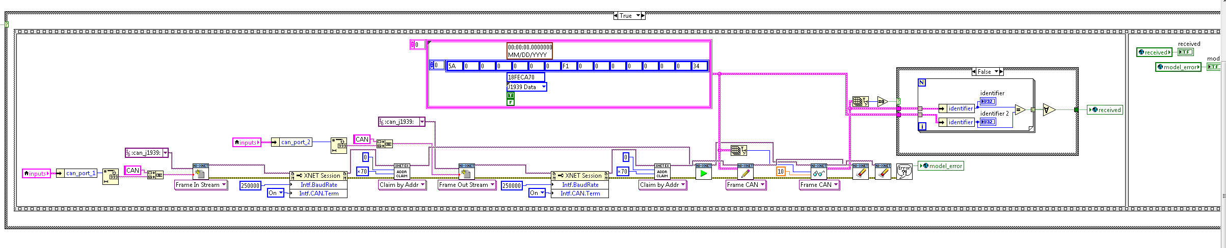
I am currenty using LabVIEW 2015 and set up a simple looping CAN test to test the J1939 XNET. I noticed that XNET seems to remove the message ID's priority. Example, I put the ID of the message to 0x18C45671 with '0 x 18' slice that contains the priority of the SAE J1939 message, she is received on the other side and displayed as "0xC45671". Why is this? I have attached a reference image.
Further reading in the software and hardware manual OR XNET to 2015 has led me to this:
"Standard frames, the full identifier is considered the CAN message identifier;
in J1939, only the PGN determines the message. Images with the same PGN but different
priority or source address are considered as the same message. "- Chapter 4, p 59.
I understand that, but I don't disagree with the implementation of X-NET that removes the priority on the side of the reception (or is it just before transmission?). I would like to keep it, but this isn't a big problem I can live with that...
Maybe you are looking for
-
Are Homebotton and Touch ID covered if they are broken?
Here's the problem: I went to the beach and unfortunately my IPhone6 belong in the sand, because then my homebotten is going crazy, I do the screenshots of all the time when I want to block my phone, I can't open the Apps, because they will close by
-
Hello So my battery won't charge. I've had this laptop for 9 months and 2 weeks, the battery stopped charging. Help, please! Thank you.
-
I can't send my messenger hotmail qwest account changed
I was recently on behalf of qwest that was connected with my hotmail account and now qwest is changing there name centrylink, my emails come well, I tried to set up a new hotmail account and for some reason I can't, but I got a hotmail link to my. q.
-
Hello It's embarrassing, but when I use this method: String fullPath = "file:///SDCard/Vehicle History Log.txt"; byte[] data = "ABC\nABC".getBytes(); String error = ""; try { FileConnection fconn = (FileConnection) Connector.open(fullPath, Connector.
-
Hello I want to retrieve the data from the xml file that is in the server. How can I do. Please answer. Thank you Isabelle