LabVIEW 8.5 SHA-1 implementation
Hello everyone,
I need an implementation of SHA - 1 for Labview 8.5.
I looked for something I could use, but I found an implementation for Labview 9 here and a link in this message that no longer works. Unfortunately, I have access to Labview 8.5, not the newer versions, so I can't use the existing screws in the box of the developer.
Can someone in this forum help me please?
Best regards
Matthias
Hi Matthias,
Here's a vi to LV8.5.
Mike
Tags: NI Software
Similar Questions
-
Hello!
I noticed that the continuous measurement and a project in LabVIEW 2012 Logging using chains instead of enums and orders from the queue. I wonder if there is a good reason for it?
Kind regards
Anguel
First, string vs enum debate is probably the version of LabVIEW vim vs emacs. There are good arguments on both sides, and I doubt that there is always a "winner".
A brief summary of our reasoning for the current state of the project examples:
- We used enums for the state machine because it is self-contained. A state machine will never tell himself to enter a State, he does not know. Knowing (as the programmer) all possible States with the help of an enum allows you to enlist the compiler in order to help us avoid mistakes to change the time (because you can't quite out an enum and LabVIEW can be said if you are not covering all cases to a structure of the case, etc..).
Enums provide greater protection and rigidity by ensuring all withdrew at the time of publishing. This is often the 'default' recommendation that we do.
- We used strings for messages in queue manager because the producer of message and the message handler could be independent processes that are reused or traded. Channels avoid the need for the compiler to be able to connect the orders and push this responsibility to the programmer. This allows you to develop some sub-components independently as long as you agree to a series of channel commands that you can manage - you need not to share a file 'messages.ctl' or 'states.ctl '. It is conceivable a loop of message management a message it does not, how you can decide to either silently ignore it or will trigger an error (as we do in the model). The strings make it also easier if you want to swap the queues of LabVIEW outside by a TCP implementation for network vacilitate or intra-Processuse communication where the other end may or may not be written in LabVIEW.
Channels to provide more flexibility (that is, you can add new commands to an existing via plugins system, you can pass parameters as part of the string, etc.) at the expense of pushing her potential errors at run time and to put more responsibility on the programmer.
- The actor's gifts frame a 3rd option - using classes such as messages. For me, it combines many of the advantages of these two enumerations (strictly typed, change errors) and strings (flexible and scalable), but with the disadvantage of being somewhat less transparent (you understand OO, be comfortable to navigate through a multitude of screws, legacy of understanding, etc.).
I don't know there are other reasons, others to the breast OR had or seen as we validated models and examples of projects in-house, but here are my reasons. We know that we can not design for each situation there - our goal is to get useful models against new users to make them aware of what well thought LabVIEW programs are similar to experienced users know their applications better and I hope they do not hesitate to change what we provide or create their own designs, when they feel it's necessary. (On a side note, please share what you come up with - a community of experts sharing models would be really useful to us all LabVIEW users).
Best regards
Simon
- We used enums for the state machine because it is self-contained. A state machine will never tell himself to enter a State, he does not know. Knowing (as the programmer) all possible States with the help of an enum allows you to enlist the compiler in order to help us avoid mistakes to change the time (because you can't quite out an enum and LabVIEW can be said if you are not covering all cases to a structure of the case, etc..).
-
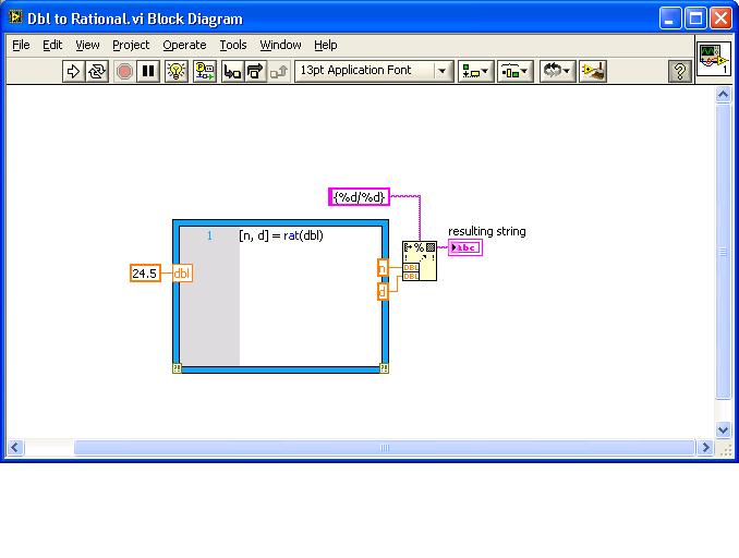
Hello
The TIFF tag header protocol requires a data type, I'm not really familiar with, the rational data type: http://en.wikipedia.org/wiki/Rational_data_type
I need to convert numbers in double precision for this type of data, for example 24.5 shall make a report of two integers: 49.2 {}. Is there an existing algorithm of LabVIEW to perform this operation? All my research NOR keep translated by interpolating Rational ClearCase or rational table. It seems to me have found a lot of the theory behind it: http://stackoverflow.com/questions/95727/how-to-convert-floats-to-human-readable-fractions
But this is implemented in labVIEW already, or should I implement the code c cited?
Thank you
Mello
This should be possible if you have available MathScript.
See attachment (LV 8.6.1)
-
Restart the VI for be new Tx params?
Hello
I am new to the use of USRPs and have very little overall experience with Labview. I'm currently implementing frequency-hopping by the example of the transmitter of package USRP. I converted most of the transmitter to the constants options since I'm mainly interested in the frequency of change in appearance and included a button to change the frequency. The problem is that I need to stop and restart the VI for the USRP starts the frequency. I thought that there must be a way to reset the VI whenever changes frequency without having to manually stop/run, but so far I have failed to find it. Is there a way?Hey cynop,
Thank you attach your VI. The first property node that you have inserted, you don't need. You can wire the frequency of your structure to deal directly at the entrance of carrier frequency of the niUSRP configuration Signal.vi. The property node that is inside the loop, this is what you need to change the frequency on the fly. When you update the control of carrier frequency on your façade, the frequency of the carrier of your USRP updates also. One thing to note is that the indicator of frequency forced on the front panel will not update. You can shoot on the frequency of the carrier under pressure inside the loop of this indicator to update. I do not recommend to do it right. The amount of time it takes the driver to query the device for frequency can be enough time to cause a buffer overflow error.
-
return on investment for the profile line variable
Hello
I built a vi with vision assistant, where the profile of a single horizontal line is included. If the acquired image had the X, Y coordinate system, I want to extend the vi so that it updates all possible horizontal lineprofiles (X 1/Y0 to X 1/Yn) line (Y0/Xn to Xn/Yn) in this order. So I have to vary the return on investment (line), but how is this possible? I have no experience in labview, so it's hard for me with the data of different types and functions.
Thanks for help
Hi Blue12,
You may not need to create a return on investment for each line. You can get information on line directly with "IMAQ-profile line. You can directly enter the coordinates of your line and out of the profile.
Please save yourself frustration and get LabVIEW training before attempting to implement applications.
Best regards, Topper
-
multiplexing of the strain gages with the scxi-1001
I am trying to write a MatLab program that uses the C++ functions. I managed in the collection of data of an extensometer, but I do not understand how to configure the multiplexing.
I use a DAQ, SCXI-1600 in a SCXI-1001 chassis with 9 input modules 8 channel universal bridge SCXI-1520.
I know that the hardware is possible to multiplex all 9 SCXI-1520 for the acquisition of data because we did it in LabView. I have currently no LabView on my computer.
My question is:
How labview use C++ functions to implement this material to record 72 straingage channels.
That's what my code looks like:
Clear, clc
rate = 100
time = 1If ~ libisloaded ('myni')
DISP ('Matlab: load nicaiu.dll')
[notfound, warnings] = loadlibrary ("C:\WINDOWS\system32\nicaiu.dll",...)
"C:\Program NIUninstaller Instruments\Shared\CVI\include\NIDAQmx.h",...
'alias', "myni")
endcards = 1
Chans = 8
taskh (1) = uint32 (1);% This is the C++ function called from MatLab-> int32 DAQmxCreateTask ('master', taskh (1))
[a, b, taskh (1)] = calllib ('myni', 'DAQmxCreateTask', "master", taskh (1))
chains of % for both channels 0 through 7 on each and SCXI-1520 cards.
taskchans = {'SC1Mod3 / ai0:7 ',' SC1Mod4 / ai0:7'};
samples = time * rate;
chanName = ";
minV = - 10F-4;
Discharge = + 10-4;
excitV = 3;
gageFactor = 2.09;
iniBrdgV = 0;
nomGageR = 350;
poissonR = 0.3;
wireR = 0;
scaleName = ";DAQmx_Val_Strain = 10299;
10065 = DAQmx_Val_FromCustomScale;
DAQmx_Val_QuarterBridgeI = 10271;
DAQmx_Val_Internal = 10200;
DAQmx_Val_Rising = 10280;
DAQmx_Val_FiniteSamps = 10178;
DAQmx_Val_GroupByScanNumber = 1;% creation of extensometer (virtual) channel
[c] = calllib ('myni', 'DAQmxCreateAIStrainGageChan', taskh (1), tank (taskchans (i)),...)
chanName, minV, discharge, DAQmx_Val_Strain, DAQmx_Val_QuarterBridgeI...
DAQmx_Val_Internal, excitV, gageFactor, iniBrdgV, nomGageR, poissonR...
wireR, scaleName);% set samplerate and number of samples
for i = 1:cards
[a, b] = calllib ('myni', 'DAQmxCfgSampClkTiming', taskh (i), cm, rate, DAQmx_Val_Rising,...)
DAQmx_Val_FiniteSamps, samples)
end
Disable the trigger for the start of the %
for i = 1:cards
[a] = calllib ('myni', 'DAQmxDisableStartTrig', taskh (i))
end% create variables to read data
readarray1 = Ones (CARDS, Samples);
readarray1_ptr = libpointer ('doublePtr', readarray1);
arrayLength = samples;sampread = 0;
sampread_ptr = libpointer ('int32Ptr', sampread);
void = [];
empty_ptr = libpointer ('uint32Ptr', Empty);Organization and reading raw data
strain = ones (maps * chans + 1, samples);
t = 0:1 / rate: time-1/rate;
Strain(1,:) = t;)for i = 1:cards
[readarray1, sampread, empty] = calllib ("myni', 'DAQmxReadAnalogF64', taskh (i),-1,-1,...)
DAQmx_Val_GroupByScanNumber, readarray1_ptr, empty_ptr, sampread_ptr, arraylength);
strain (chans * i-(chans-2): chans * i + 1, :) = readarray1;)
end% Stop all tasks
for i = 1:cards
[a] = calllib ('myni', 'DAQmxStopTask', taskh (i));
If a == 0
fprintf (' slaughter task %s...) OK \n ", tank (j (i)));"
on the other
fprintf (' start task %s...) Failed \n ", tank (j (i)));"
end
end% Clear all tasks
for i = 1:cards
[a] = calllib ('myni', 'DAQmxClearTask', taskh (i));
If a == 0
fprintf (' task claire %s...) OK \n ", tank (j (i)));"
on the other
fprintf (' task claire %s...) Failed \n ", tank (j (i)));"
end
endIt is the General form of my code.
I tried to do one task per channel, but I can start only one task at a time.
I tried to use DAQmxSwitchCreateScanList and DAQmxSwitchSetTopologyAndReset.
-> but I don't know what the name of device for the switch.
If anyone can explane how all these SCXI-1520 multiplex LabVIEW cards that would help a lot.
Thank you.
OK, I found the solution to this problem.
The SCXI-1600 multiplexes based on which channels have set you up. I simply add all 72 channels to the taskh (1) with the function DAQmxCreateAIStrainGageChan (...) then my samples are multiplied by the number of channels, I added.
-
implementation of a function of time transfer real Labview program
Hello
I want to spend my control signal U through the 146 function /(S+276) for U_filtered
How do I?
I tried a low-pass filter, but I have the same results in comparison with Matlab.
I mean I want to have:
U_filtered = 146 /(S+276) * U.
I have attached a picture for the signal U (yellow) and U_filtered (pink) in Matlab.
I want to use in a real-time application
Thank you
How you implement the function of transfer in labview?
I think this should be a separate implementation and maybe you already do. So forgive me if this is something you already know.
Please see http://en.wikipedia.org/wiki/Low-pass_filter#Discrete-time_realization for an excellent time discreet introduction, low-pass filters.
Essentially, you have to implement a discrete equation to achieve this. Something like:
y(k+1) = 0.53 * alpha * x (k) + (1-alpha) * y (k)
where alpha is related to the low-pass frequency and the frequency of sampling by alpha = flp /(fs+flp), flp is the low frequency of success and fs is the sampling frequency.
In your case, flp = 276 and fs, it's whatever you choose to implement: it is the speed at which your loop runs on the RT or the FPGA or whatever. If speed is not a problem, I recommend 5000 rad/s or above as a starting point.
The factor of 0.53 above is just the gain of the filter described you 146/276.
-
String implemented in labview code
Is there a LabVIEW implementation of string for imaq images codes? I would include the image processing chain codes but don't see them in the VDM.
There is no code in LabVIEW image processing chain accompanies this VDM from what I can find. I have comfirmed this with a few other engineers as well.
-
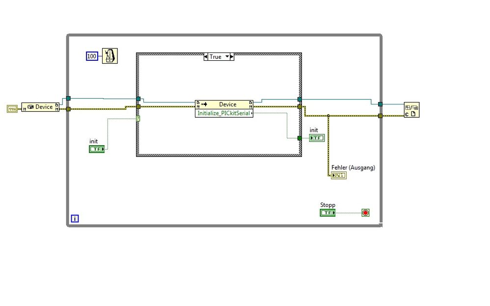
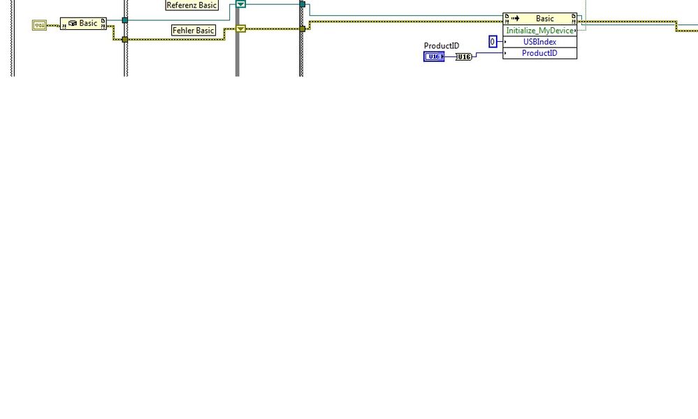
Implement pickits.dll in LabVIEW
Hello
I have problems with the pickits.dll chips. I want to implement the dll file in Labview and communicate with a material called Analyzer series of LIN of microchip.
When I run my Labview VI, it cannot communicate with the device.
It comes to my composition in Labview that does not work.
This composition is created on an OS WIN7/64 bit and a system 32-bit/WIN XP. The two does not work.
The Analyzer is run with the chip Network Analyzer(64bit) demo application.
I downloaded the LIN Serial Analyzer Update v2.05 (64-bit) of the homepage of the electronic chip and with this application, it works.
The pickitS.dll works inside LabView correct. When I run the Prototype of the "Get_PickitS_DLL_Version" function, it returns the correct Version of the DLL.
Is my composition in LabView, right?
Any that work with the Analyzer series of LINEN or similar devices of microchip?
concerning
Hello
I solved the problem. For initialization of the FLAX series Analyzer, you have to take the ' base' constructor and the 'Initialize_MyDevice' method with the parameters USBIndex = 0 and ProductID = 0xA04. With this basic adjustment, you can initialize the device. Then you must set the baudrate of 19200 for Bus LIN.
Feel free to ask me if you have problems with your device.
-
Implement and control 'meter' in S7 - 300 by the OPC and LabVIEW
Hello world
I use a S7-300 PLC and OPC Server for my projects. I have a problem: S7 - 300 has a meter module which digital signal of County. I only can implemented using SIMATIC STEP 7. Can I set up the meter module using only the server OPC and LabVIEW
does anyone have a solution or an idea for my problem?
could you please help me...
Thank you
Hi Echion,
NOR-DAQ (MX) is used only for material OR: no you can not use it.
To program the controller you must use the right programming environment. For Siemens S7, you need to use Simatic (or perhaps some other 3rd party software supporting IEC61131). Point.
The OPC server is used only for the exchange of data. This is no interface programming!
-
How to implement the wafer map using LabVIEW?
Hello LabVIEW Masters!
I have a project which includes control and searching for information on a PROBER. One of the difficulties I have now is how to implement a WAFER card using LabVIEW. According to the requirements of my client, the element of pads varies between 6 k and 23 k. I guess that do everything (a = a ctl/indicator led) will be a hell of a task, especially on how to effectively manipulate each elements. Does anyone have a better idea on the way whose that?
Please, I seriously need your help...

Thank you and best regards,
Dennis DG
Hi Dennis,
This wafer GerdW post card appears to me as a sort of histogram (for example http://www.ni.com/white-paper/4158/en#toc3);
Altenbach post well this example that shows how to use a plot of intensity to create a 2d histogram:
http://forums.NI.com/T5/LabVIEW/overlay-plots-as-intensity-graph/m-p/211222#M119248
Learn how it works and try to adapt it to your specific task.
Alex
-
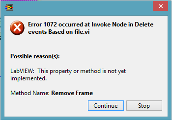
VI LabVIEW 2012 script: Method - delete not yet implemented framework
Hi all
I use screws LabVIEW 2012 script to delete the events to the event structure. For some reason, I get the following error
Is it possible that a method is listed without running? Suggestions to overcome this is welcome. Thanks in advance
Kind regards
S.P.Prasaanth
According to this http://forums.ni.com/t5/LabVIEW/Remove-Frame-Not-Implemented/m-p/2100644/highlight/true#M684629 post: Yes, it can be.
But it seems that implemented in LV2013: http://forums.ni.com/t5/LabVIEW-Idea-Exchange/Configure-Event-Case-with-Scripting/idc-p/2523818/high...
-
implementation of generator electric automation in labview
I'm a grad student. I am doing my final project on automation of generator.
my project is->
I want to view, input voltage (mains voltage), temperature, fuel level, current load. If the supply voltage is interrupted, it automatically goes to the other power to start the generator. Now he's going to keep the generator temperature detection. If it exceeds 50 degrees celcius then generator will be automatically stopped. If the fuel level is below certain level, then it will sound the alarm. At the same time, I want to display the fuel level and temperature on the LCD.
It comes to my project.
I want to ask can I implement this project using the FPGA and LABVIEW?
What devices I have to buy for this (FPGA board)?
about, what will be the cost of Board and sensor devices?
Help, please. I'll be very grateful to you.
I agree with Smootastic, but NEITHER will not be able to provide everything you need to make all these measures. You talk about a wide range of sensors for all these tasks. You will need of thermocouples and RTD/themistors for measurements of temperature (see www.omega.com or www.marlinmfg.com), you will need a level indicator (Omega, Newark, Allied Electronics, etc.) and ammeter with alarm output (Grainger? McMaster Carr?). You have a catalog to search for.
I don't know FPGA is needed to do this, have you considered Compact Fieldpoint? Your rep OR can advise you better.
-
Implement the Std::Vector < < Point2i > > Std::Vector in dll wrapper for LabVIEW
Hi, I'm writing a wrapper dll that using OpenCV function. I had been sucessfully implement Std::Vector
by referring to "An array of clusters to a dll C sending". And now, I want to implement the Std::Vector<>
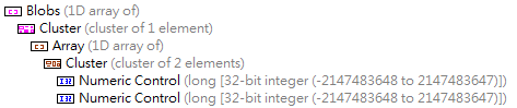
> who is a lot like table 2D but each line items may be different. In LabVIEW, I attribute a range of cluster of the dashboard cluster of 2 I32 elements, structure which is shown below:
I think it has the same functionality as Std::Vector<>
> in C++. So I plug this data on the "Call library function node" structure and generate C code that indicated below:
/* Call Library source file */

#include "extcode.h"

/* lv_prolog.h and lv_epilog.h set up the correct alignment for LabVIEW data. */
#include "lv_prolog.h"

/* Typedefs */

typedef struct {
    int32_t elt1;
    int32_t elt2;
    } TD4;

typedef struct {
    int32_t dimSize;
    TD4 elt[1];
    } TD3;
typedef TD3 **TD3Hdl;

typedef struct {
    TD3Hdl elt1;
    } TD2;

typedef struct {
    int32_t dimSize;
    TD2 elt[1];
    } TD1;
typedef TD1 **TD1Hdl;

#include "lv_epilog.h"

void funcName(TD1Hdl arg1);

void funcName(TD1Hdl arg1)
{

    /* Insert code here */

}
Then, I write this code show below in dll wrapper:
void funcName(TD1Hdl Blobs) { vector < vector> blobs; // Distribute contents of blobs to Blobs from LabVIEW MgErr err = mgNoErr; size_t arraySizeInBytes = Offset(TD1, elt1) + sizeof(TD2)*blobs.size(); // Determine row size err = DSSetHSzClr(Blobs, arraySizeInBytes); if (err != mgNoErr) return; (*Blobs)->dimSize = blobs.size(); for (size_t i = 0; i < blobs.size(); i++) { arraySizeInBytes = Offset(TD3, elt) + sizeof(TD4)*blobs[i].size(); // Determine col size of each row err = DSSetHSzClr((*Blobs)->elt[i].elt1, arraySizeInBytes); if (err != mgNoErr) return; /*......................*/ } } When I call LabVIEW dll, the program get interuption(i.e shutdown) on line where I want to determine the size of each row.
Could someone give me some suggestions on this subject or promote another application of this requirement?
Thank you very much.MgErr funcName(TD1Hdl Blobs) { vector < vector> blobs; Labeling(image_binary, blobs); // the prototype of this function is: Labeling(Mat &binary, Vector Personaally I've usually done like this. Already, the tar of DSSetHSzClr() indicates if there was something wrong and that the handle cannot really become NULL to call this function.
To be entirely correct and safety integrated, you must do more than that. But as long as you assume that the incoming picture is always smaller that the outgoing Board will be (usually it be 0 items when you enter this function, but if you reuse sort table in the diagram, by storing it in a registry change for example, this may not be true more) this will be enough.
-
How to implement logical equations such as LabView?
Hello
I have this bit logical test I need to implement a Labview code.
Can I use formula node or anything similar to this already in Labview?
"((var & (1
a certain number of bits. 0 is the least significant bit.
Thank you
Do

Spin and not equal to zero
Maybe you are looking for
-
About two weeks ago my phone turns off randomly. I could not turn it back on during a day. So, I decided to restart the phone using the trick House and key lock (pushing down both). The phone told me to connect it to iTunes. So I did and things were
-
A couple of my friends of e-mail do not know how to highlight, copy, and paste the address into their browser. When they click on it and it isn't a link, they just delete the mail. I have to open the browser and sign in my email here for them to see
-
How can I move bookmarks from the left sidebar?
I want to move my bookmarks sidebar, from left to right and ask them to close after I take to open. How can I achieve this?
-
Failure of Vista Ultimate Update window
I can't run/install updates. Get the error message that I can't install updates at all. Windows Vista Ultimate Edition. I get the following error code... WindowsUpdate_80070663""WindowsUpdate_dt000"
-
Hello guys! I want to buy a new HP PC, and I seriously think to buy HP 15-r219 nx. Before that, I want to know if this model has a backlit keyboard, so I can use it when there is no light around. If she is not a she, can you please suggest me those h