LabVIEW FPGA and real-time communication module
Hi all
I created a small program in labview FPGA which gets continually distance from the HC - SR04 ultrasonic sensor. The rest of the robot program is written in the time module real Labview. Is it possible that the distance calculated by FPGA module to read in time real module.
I used the FPGA just because there micro-deuxieme counter, which helps me get the distance from the ultrasonic sensor.
Thanks in advance.
There are many ways this can be done, according to your needs.
See the help article transfer of data between the FPGA and host (Module FPGA) for a breakdown of each method.
Tags: NI Software
Similar Questions
-
What are the differences between LabVIEW and LabVIEW FPGA and LabVIEW RT
I need a comparison of LabVIEW, LabVIEW FPGA, and LabVIEW RT
Sorry, I misunderstood.
LabVIEW RT (LabVIEW Real-time) combines graphical LabVIEW of programming with the power of a real-time operating system, allowing you to create applications in real time.
-
LabView is in real-time for Compact FieldPoint necessary?
Hello!
LabView is in real-time for Compact FieldPoint (CFP) necessary?
(in German: Ist für die von Compact FieldPoint LabView time use real necessary?)
Thank you.
Bye, Ouafa
Hello
If you just want to use Labview for logging and graphics (via Ethernet) AND that you do NOT use a CFP-real-time controller, you don't need to LabVIEW Real-time.
For example if you use OR cFP-1804-Ethernet/Serial Interface for Compact FieldPoint.
(http://sine.ni.com/nips/cds/view/p/lang/en/nid/202527)
If you are using a controller real time you WILL LabVIEW Real-time.
You can't function without it!
Best regards
Mencef
-
LabVIEW 2014 SP1, hardware and real-time PXI
I'm doing my third LabVIEW Wipe/reinstall in as many days, completely frustrated (and after several calls an hour with the support of NEITHER). Here's the situation:
I wrote a fairly large (1000 VI) project of Acquisition/control of our graduate students data used for behavioral experiment on sound localization. It was developed in 2012 LabVIEW with the module running on a PC/PXI system real time. It worked very well and was brought successfully under LabVIEW 2014 (with upgrades comparable to the software of the PXI.
About 18 months ago the students began to write their theses, and at one point stopped gathering data. Also, at some point, I upgraded the software on this system to LabVIEW 2014 SP1, but I am not sure that I never tested my software with this new system.
This week, I pulled up the system to use MAX to open some test on the PXI multifunction and DIO card panels to control manually one of the stimuli. I discovered that MAX could not communicate with the advice on the PXI system - he attributes them as devices VISA, indicating each Board with an icon with a red X means that he could not communicate with the IP that I had assigned to PXI. Yet, MAX (a) could "discover" this PXI, (b) MAX can 'see' its IP address, and (c) Windows could not only Ping the IP, but could FTP on the drive of the PXI and I could move files back and forth.
I did two sequences complete "Wipe/reinstall" using LabVIEW 2014 SP1, all giving the same result. I know it has worked in the past, including when I installed LabVIEW 2014 (without SP1), something I repeat myself now with my third installation. I discussed with OR (thin?) possibility that there is a "hidden defect" in the Distribution of the SP1, one that is visible to LabVIEW RT users using PXI hardware and go unnoticed because (a) install a few sites of LabVIEW versions SP1, (b) a minority use the RT Modules and (c) PXI is "old material".
If anyone has such a system or saw a similar problem, please answer. I'll do a follow-up post if I managed to 'fix' my system by this last reinstallation "a solution of worked before."
Bob Schor
Well, the answer is that, in my system, LabVIEW 2014 SP1 with LabVIEW Real-time connected to a PXI system does not appear to connect to boards plugged into the chassis. Returning to LabVIEW 2014 (fall release), installed in exactly in the same way that the three failed attempts of LabVIEW 2014 SP1, works immediately. Engineers OR will try to duplicate/verify/possibly patch? in this issue.
Bob Schor
-
Zip file and iso LabVIEW FPGA Xilinx tools 12.4 Module is broken
I downloaded the two zip file of LabVIEW FPGA Module Xilinx tools 12.4 and iso image file three times to make sure that both files are broken and can not be installed!
The size of the file is so large about 3g. It would be better to double-check before you download on the Web site.
-Very well,.
The download is complete and the standard Windows Extraction tool worked, WinRAR worked and 7Zip worked (and no, I don't know why, I installed all). I did download a wireless network that does not have direct access to our internal servers, it should therefore be a test valid. If the link I provided above was not that you used (probably isn't, because it is not an ISO option), could you please provide me with a link to the page that you used so that I can test and repair? In the meantime, the link above should work for you.
-
Algorithm of PID in 'PID and Fuzzy Logic Toolkit' and 'real time Module ".
Hi all
I am recently using LabVIEW 2011 and 2011 real time Module. My application requires the PID control.
Now, I have a problem. In the manual for "And Fuzzy Logic Toolkit PID", Chapter 2 "algorithm PID" it indicates non-interactive algorithm (also called the ideal algorithm, Standard or ISA) be used in all the screws of PID in the Toolbox. It seems that Yes from source code. However, in Chapter 3, "Using the PID software" arrays of calculation of PID parameters based on method of Ziegler-Nichols, which was developed for the interactive algorithm (also called the series, the real classic algorithm). D action has been included in the scheme of control, the settings may be different for the two algorithms. In fact, Cohen Coons and adjustment PID Lambda rules can be used for the algorithm used by the box tool with no conversion.
In addition, there is a PID function block comes with the real time Module, and I know not what PID algorithm it uses. Can someone help me?
Thank you in advance.
Su
In the "and Fuzzy Logic PID Toolkit, we use the University structure to implement all algorithms. Tuning techniques we show on the manual to express the original work and we try to keep the same as you would look at the literature. However, in our implementation of autotuning internally converted to the structure used by our algorithms to keep compatibility with our own implementation.
If you use an external source, you can use the Conversion.vi of Structure PID to change University, parallel or series of parameters in one used by our algorithm.
The PID included with the real time module is a 'copy' of our algorithm, and they have the same settings and behavior. The only advantage to use this function block, you have access to the parameters through variables.
Hope this helps...
-
Real-time communication between PHP and Flex application
My client wants to replace the buttons 'Refresh' in their Flex/PHP app with updating in real time, so as to data changes, it is pushed to the client.
I came across a few articles which cover this topic, but I'm hard-pressed to find the best approach. Can someone suggest possible solutions?
Any help would be appreciated. Thanks in advance.If your server supports K 100 simultaneous connections with push (permanent connection)
It can be used 100K users simultaneous apps. With polling stations, it can serve more
100 k because it opens a connection and then it closes once the answer has
been sent, so until this client polls again it can handle other requests of
other customers...
C
-
Deal with failure when using LabVIEW 2011 and DSC MODBUS communication
I'm currently reading from operating records a PLC with MODBUS/TCP. I confirmed that the PLC will update the values and in response to a MODBUS communication correctly by using a third-party program called Modbus Poll. However, when I try to query the PLC using the LabVIEW shared variable engine, I am unable to read the values of the same addresses that I consult with Modbus Poll.
My installation is simply to a PC directly connected to the controller via Ethernet without a router between the two. I'm using LabVIEW 2011 SP1 with the DSC module.
I opened the Manager of distributed systems OR to display the State of all variables in the Modbus Library that I created, and I noticed that the ILO CommFail permanently the value 'true '. All other variables with a 'read' access mode signal "failure of process". I tried to restart the process and stop and start the local variable engine without success. I also restarted my computer several times to see if any services did not exist, but this does not appear to have solved the problem.
Finally, I resorted to listening to communications on the network card I have the PLC connected via Ethernet using Wireshark and found that while Modbus Poll communicates with PLC, number of MODBUS and TCP packet is sent and received. However, when using only LabVIEW or the DSM OR communicate with the controller, there don't seem to be any communication on the network card.
Something that may be interesting to note is that I could communicate with the PLC and to read values with the DSM just once, when I understood everything first what address I should be reading of. All of this has stopped working shortly after. Prior to this, 'CommFail' was not generally set to 'true' with my current setup. Thinking it was my firewall, I have since disabled my firewall, but this seems to have had no effect on the problem either.
Any help on this would be appreciated.
So, I thought about it. It turns out that the IP address of the server i/o MODBUS must be set to the address of the MODBUS slave, not the local computer. The address of the i/o MODBUS server is defined by the navigation in the Explorer window projects, expanding the variable engine shared library for MODBUS and right click on the server MODBUS (for example Modbus1) item and select Properties.
In addition, the addresses seem to be shifted by + 1.
Thanks for the tip so.
-
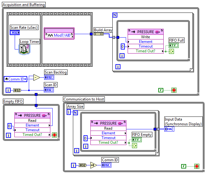
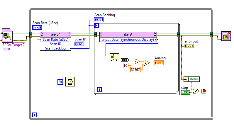
FPGA FIFO real-time error-61206
I used this white paper as a base for my code. My FPGA look like:
And my time real-time (RT):
I am using a cRIO-9022 and now just trying to get the foundations buried for my project. The problem is that the side FPGA works well but environmental RT takes maybe 2 or 3 seconds and close with this error:
Code:-61206
Source: Read/write in FIFO_pressure_RT.vi control
I have not dealt with the FIFOs in LabView before I have no idea what is the cause. Any ideas?
Thank you
Logan
What version of LabVIEW are you using? In LabVIEW 2011, if orders or the lights on the front of the FPGA had a jump of line or transport back in the label, the question would be filling in the read/write control node, but you would see this error. It seems that Input Data (synchronous display) probably has a newline character that could cause this. That the problem has been solved in LabVIEW 2011 SP1, but what happens if you remove the line break and recompile the FPGA VI?
-
The PSC-2000 is programmable with LabVIEW 2010 SP1 / Real Time 10.0.1?
I have a PSC-2000 camera I want to use for a small project. I see on the site OR that it is said»
- "Support for LabVIEW Real-time 8.5.1 and earlier" and "Support for Windows Vista and earlier versions. It means that I can not use the latest version of LabVIEW (2010 SP1) with time real (version 10.0.1) running on a Windows 7 computer? If not, what version of LabVIEW, real-time and operating system do I need?
-
Hi all
We have NI 9421 digital input and digital output NI 9472 Modules. We can run these modules into a VI under the 9073 cRIO chassis. While we have added the FPGA target under the same chassis, we cannot use the modules. We also install the scan engine.
How can we use FPGAS and i/o Modules at the same time?
Once you add a target FPGA in CompactRIO chassis, when you deploy the code, the cRIO is configured for the FPGA mode, which requires a bitfile compiled to connect with the C Series modules. Remove the target FPGA or changing the mode of chassis in the project and by redeploying must reconfigure the cRIO for scan Mode, which allows you to use the IO module directly from the RT VI.
For more information, see this post.
-
Frequently corruption file characterset OCR and real-time CVS1454 exe file
HI I am facing strenge same problem in the application of vision. I'm using equipment NI CVS 1454. Is there an OCR on CVS application that inspect the product on the conveyor. I made different characters to choose file of different labels on the product. Now main problem is sometimes not exactly when my chracterset file, Pattern matching templete and corrupts my exe in real-time. I joined a few ok and corrupted file characterset here and also an exe in real-time.
When I open my file (.abc) characterset in Notepad, that I found damaged files after entering text.
####
#Date: Wed, Aug 1, 2008 11:28
#OSName: PharLap
#OSVers: 13.0
#AppName: PH_EXEC
#Version: 8.5
#AppKind: AppLibLVRT. DLL loads the address: 0x002F6000
I don't understand how this error massage journal if written in .abc or rtexe files, which make it currupt... I have also attached my structuring code image file.
Dear prashantpatel21,
I do not know how to disable the log of LabVIEW RT errors, at least, is not that you or I could have access.
It's the idea that deactivation of LabVIEW RT logging of errors will decrease even more the impact of corruption?
Have you made progress with your service request?
~ Nate
-
Hello..

I'm a newcomer in LabVIEW... and so far, I was working with LabVIEW 7.1 for my projects... but now I need to work in LabVIEW 8.5 for my next project... So can someone please tell me where can I get the evaluation version of LabVIEW Real-time and LabVIEW 8.5... so that I can practice with it...
Thanks in advance...
Before installing the new version of LabVIEW, copy the folder to C:\Program NIUninstaller Instruments\LabVIEW 7.0\ structure in a separate folder, disk, or CD. Copy everything in the folder.
Install the new version of LabVIEW. The new facility will remove or modify the drivers used by LabVIEW 7.
When the LabVIEW 8.x installation is complete, restore the folder structure for LabVIEW 7 from your backup copy. Makes no changes to the new folder for LabVIEW 8.x. The two versions will be available.
Caution:
(1) do not run both versions at the same time.
(2) be very careful about the conversion of your old code. If you convert anything, rename it and all the side screws that are associated with. Copy it to a new folder before converting.
Using this method, I have a computer with 4 or 5 versions of LabVIEW coexisting peacefully. Don't forget to think about conversions before making them. It is difficult to recover the inadvertently conversion.
-
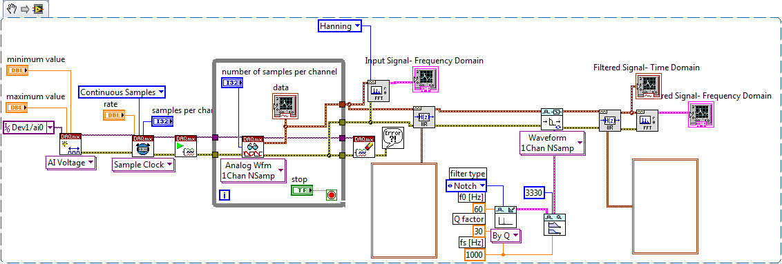
Continuous data acquisition and real-time analysis
Hi all
It is a VI for the continuous acquisition of an ECG signal. As far as I understand that the analog read DAQmx VI must be placed inside a while loop so it can acquire the data permanently, I need perform filtering and analysis of the wave in real time. How I implemented the block schema means that data stays int the while loop, and AFAIK the data will be transferred on through the tunnels of data once the loop ends the execution, it clearly isn't real-time data processing.
The only way I can think to fixing this problem is by placing another loop that covers the screw scene filtering and using some sort of registeing shift to transmit the data in the second while loop. My question is whether or not it would introduce some sort of delay, and weather or not it would be supposed to be the treatment in real time. Wouldn't be better to place all the screws (aquicition and filtering) inside a while loop? or it is a bad programming practice. Other features I need to do is back up the data I na file, but only when the user wants to do.
Any advice would be appreciated.
You have two options:
- A. as you said, you can place the code inside your current while loop to perform the treatment. If you're smart, you won't need to put one another while loop inside your existing (nested loops). But it totally depends on the type of treatment that you do.
- B. create a second parallel loop to perform the treatment. This would be separate processes to ensure that the treatment is not obstacle to your purchase. For more information, see here .
Your choice really depends on the transformation that you plan to perform. If it's much the processor, this could introduce delays as you said.
I would recommend that you start at any place in the first loop and see if your DAQ buffer overruns (you can monitor the rear of the buffer during operation). If so, you should decouple the process in separate loops.
In what concerns or not ' it would be considered as real time processing ' is a trick question. Most of the people on these forums say that your system is NEVER in real time because you're using a desktop PC to perform processing (note: I guess it's the code that runs on a laptop or desktop?). It is not a deterministic systemand your data is already "old" by the time wherever he leaves your DAQ buffer. But the answer to your question really depends on how you define "real time processing". Many lay it will set as the treatment of 'live' data... but what is "actual data"?
-
How do I get the computer hours and appear in labview? Get real-time!
Hello!
I got it!
I saw a topic and gave all right.Thank you

When I tried to add a new target under LabVIEW 2010 SP1, the PSC-2000 was not among the choices.
As the support NOR documents indicate, you need LV version 8.5.1 or earlier to program the cFP-20xx devices family. Version 8.5.1 of LabVIEW does not work under Win7. You will need Windows Vista or something earlier like XP.
Maybe you are looking for
-
How can I email picture directly from the new "Photos"? (on El Capitan)
-
Satellite X 200: Cannot write to the memory card error message
Hello Can help you, I have a X 200 with XP Professional installed I continue to receive errors saying "the memory could not be wrtitten" I returned the machine to your service center, but they said that they could not work on the machine, unless Vist
-
Satellite L855-150 - USB3.0 External HDD does not work when connecting to USB3.0
Hello I tried 2 times to get a SATA-online work drive HARD USB 3.0 adapter when it connects to the USB 3.0 my L855, but each time it failed.First time Windows has recognized a new USB device but didn't install the new HARD drive (HARD drive was taken
-
Using a FP-I-V5 in differential mode
Hello I'm creating an application by using the Modules of Point field. I use some memory twin for i/o modules. Does anyone know how we should connect module FP-I-V5 channel as differential. Examples of the operating instructions do not cover the case
-
Desktop computer do not start; black screen; keyboard does not.
Ok. I turned on my desktop computer tonight and all I get is a black screen. Keyboard does not work either. Has gone through all the troubleshooting suggestions that I could find online (using my laptop), but nothing works. I think maybe an autom