LabVIEW FPGA failure with compiler Xlinx?
I'm in LabVIEW FPGA 8.6 with NOR-RIO 3.0.1 (to 8.6). When I compile a simple program, I get the notorious:
«Error starting compile step: make sure that a compatible version of Xilinx tools is installed in the location specified in the setup of LabVIEW FPGA.»
I checked the FPGA compile server and I ran the utility fixTlink.VI with no improvement. This produces two identical PC, neither one having a FPGA installed card.
Any ideas?
After further analysis, the problem was to be in our facility in LabVIEW FPGA 8.6. Using the correct Installer of NEITHER solved the problem.
This thread is now resolved.
Tags: NI Software
Similar Questions
-
LabVIEW FPGA CLIP node compilation error
Hello NO,.
I work on an application for my Single-Board RIO (sbRIO-9601) and faced with a compile error when I try to compile my FPGA personality via the ELEMENT node. I have two .vhd files that I declare in my .xml file and all at this point works great. I add the IP-level component to my project and then drag it to the VI I created under my FPGA.
Within the FPGA personality, I essentially have to add some constants on the indicators and entries CLIP to my CLIP out and attempt to save/compile. With this simple configuration, I met a compilation error (ERROR: MapLib:820 - symbol LUT4... see report filling for details on which signals were cut). If I go back to my VI and delete indicators on the output (making the output pin of the CLIP connected to nothing), compiles fine.
I've included screenshots, VHDL and LV project files. What could be causing an indicator of the output of my VI to force compilation errors?
Otherwise that it is attached to the output ELEMENT, a successful compilation...
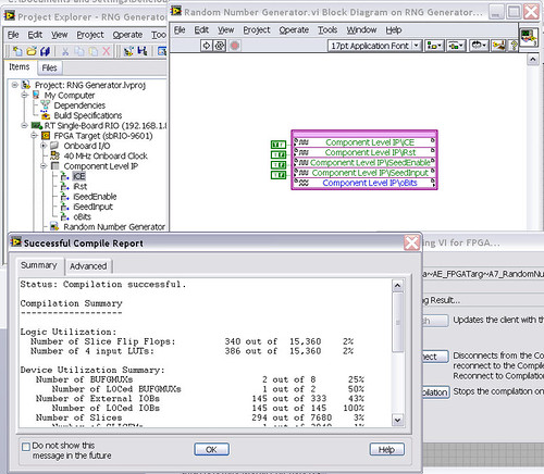
After that the output indicator comes with CLIP, compilation to fail...

NEITHER sbRIO-9601
LabVIEW 8.6.0
LabVIEW FPGA
Windows XP (32-bit, English)
No conflicting background process (not Google desktop, etc.).Usually a "trimming" error gives to think that there are a few missing IP. Often, a CLIP source file is missing or the path specified in the XML file is incorrect.
In your case I believe that there is an error in the XML declaration:
1.0
RandomNumberGenerator
urng_n11213_w36dp_t4_p89.vhd
fifo2.vhd
This indicates LV FPGA to expect a higher level entity called "RandomNumberGenerator" defined in one of two VHDL files. However, I couldn't see this entity in one of two files. If urng_n11213_w36dp_t4_p89 is the top-level entity, edit the XML to instead set the HDLName tag as follows:
urng_n11213_w36dp_t4_p89 Also - in your XML, you set the 'oBits' music VIDEO for output as a U32, however the VHDL port is defined as a vector of bits 89:
oBits: out std_logic_vector (89-1 downto 0)
These definitions must match and the maximum size of the vector CLIP IO is 32, so you have to break your oBits in three exits U32 output. I have added the ports and changed your logic of assignment as follows:
oBits1(31 downto 0)<= srcs(31="" downto="">
oBits2(31 downto 0)<= srcs(63="" downto="">
oBits3(31 downto 0)<= "0000000"="" &="" srcs(88="" downto="">Both of these changes resulted in a successful compilation.
Note: The only compiler errors when you add the flag because otherwise your CUTTING code is optimized design. If the IP is instantiated in a design, but nothing is connected to its output, it consumes all logic? Most of the time the FPGA compiler is smart enough to get it out.
-
LabVIEW FPGA Module 2015 Compilation to PXIe7820 with 'no timetable '.
I did a first compilation for the SMU with the Xilinx Vivado 2014.4 tool 7820 (64-bit). Compilation report said.
Compilation successfully completed.
Use of the device
---------------------------
Total bands: 19.1% (25350 4848)
Records of slice: 6.9% (13937 on 202800)
Slice lUTs: 12.3% (101400 12430)
Block of Rams: 0.9% (3 out of 325)
DSP48s: 6.2% (37 out of 600)Calendar
---------------------------
None.Compile time
---------------------------
Introduction date: 16.07.2016 12:48
Date recovered results: 16.07.2016 12:59
Waiting time in the queue: 00:08
Compilation of time: 10:16
-Generate a Xilinx IP: 00:00
-Summarize - Vivado: 04:18
-Optimize the logic: 00:14
-Place: 01:17
-Optimize the Timing: 00:18
-Road: 03:04
"- Generate the programming file: 00:56.This means no timetable? The embedded clock's 40 MHz. It runs with this clock? Beacause 7833 compilations for the pci or pcie 7842 report displays the maximum clock time.
Hello
"none" means simply from what I can understand, that there is no violation of timing. The source of synchronization that will be used is (as you have already suspected it) on-board 40 MHz clock.
As to why you don't get a mention of the MiteClk and the ReliableClk in summary, I think that it is due the 7833 and the 7842 relying on FPGA Virtex-II and Virtex-5, while the 7820 uses the Kintex-7 family. Depending on what type FPGA using different estimates regarding the use of the device and synchronization are not always available.
As I said, as long as you don't get not an error of timing and your compilation is completed successfully, you should be fine.
Kind regards
Alex
-
FPGA code with the evolution of the modules
I need to create FPGA code to a cRIO-9072 facing the development of the modules.
My cRIO will have a number any NI 9203 (analog acquisition) and modules OR 9411 (acquisition digital) as inserted by the operator. When turning the power on, the system must identify two possible modules were inserted in each of the slots. Subsequently, he will then know what choices of code to call to acquire data from the individual modules.
I found the article in the knowledge base for CRY that queries each module and again reports the type of module and I can use it to successfully detect modules, but what LabVIEW fails to allow me to do this is to compile my FPGA code that was designed to deal with possible modules. After compiling, I get the error: "IO found point FPGA project. You must add the I/O item in the Project Explorer window, or select a different element in the control of FPGA of IO or the constant"because the compiler requires the appropriate modules are configured in the LabVIEW project. Unfortunately, this would require two different modules to be configured for each slot at the same time as there are sections of code for the 9203 modules and sections for 9411 modules for all eight locations coexist in a vi.
Anyone have any ideas on how to get LabVIEW to compile my FPGA code somehow?
Many thanks in advance,
With the current draft of LabVIEW FPGA, you cannot compile a LabVIEW FPGA VI which manages several configurations of C Series modules.
For your application, you must create a target of your project for each of the possible configurations of module and build the corresponding FPGA VI. Then, compile each of the screws to create the necessary for each configuration FPGA bitstream. Then in your host VI, you can detect what the current configuration of the module and download the binary stream appropriate for the FPGA. Another issue to consider is that the reference to the FPGA VI/bitstream returned by the open FPGA VI reference function will be unique to each bitstream/module configuration. So in your host VI, you'll need treat each configuration of the module with a separate set of code by contacting the FPGA.
If you consider only two different modules and an eight slot chassis, there are 9 modules possible combinations. The condition would be to the end user to place all modules of the same type together, either from the left or the right side of the chassis.
-
The project-centric issue of peer to Peer with an external compiler in LabVIEW FPGA
Hi all
FPGA OR Version: 14.0
I have an application developed in LabVIEW interfacing FPGAs developed in LabVIEW FPGA making of peer to peer Communications.
Everything works fine.
I try on the port to Visual Studio 2013 (on the same PC) and am able to communicate with the FPGA very well using the C API.
However, I have a problem now with the help files or the peer supported external compiler peer.
I get these errors:
1. cannot open the file source 'PublicIncludes/nistreamCommon/prefix.h '.
2. impossible opening the file source 'PublicIncludes/nistreamCommon/postfix.h '.
in
c:\Program Files (x 86) \National Instruments\Shared\ExternalCompilerSupport\C\include\nip2p.h
in my project...
I looked in the folder c:\Program Files (x 86) \National Instruments\Shared\ExternalCompilerSupport\C\include\ and the PublicIncludes\nistreamCommon folder does not exist.
What I am doing wrong?
Hello!
It seems that you have worked with another engineer of Applications on this issue. For the love of documents, the nip2p library is not supported in CVI. There has been cases where users were able to get this work to comment on the two header files.
Thank you!
-
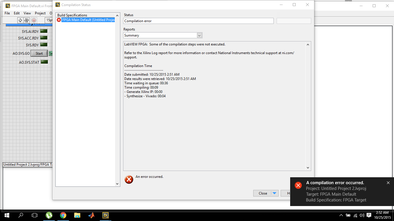
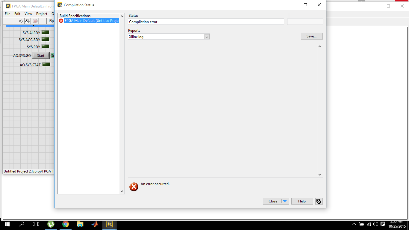
LabVIEW FPGA, 2015 compilation error
I've recently switched to LabVIEW 2015 and I'm working on OR myRIO. So also installed myRIO 2015 bundled software. The problem I have is that the compilation of fpga fails within 10 seconds.
and the target Xilinx journal report is empty
The first time when I tried to compile on 2015 version, it failed and the message box that failed came alongwith the avast antivirus warning for malicious activity. I reported it as wrong and now I tried several times with avast shield disabled control, but the results are the same. While the version of labVIEW 2014 works very well.
Now, I'm sure that there is something wrong with the installation of Vivado because this dll is part of it. The dll must be default in the2014_4\lib\win32.o directory C:\NIFPGA\programs\Vivado if you are using an operating system for 32-bit AND also in C:\NIFPGA\programs\Vivado2014_4\lib\win64.o If you use a 64-bit operating system. If the dll is not here, it is probably that the anti virus (I've never seen what happens to Xilinx but I have for other stuff).
I'm emphasizing the 2014_4 because LabVIEW 2015 uses Vivado 2014_4 while 2014 LabVIEW uses Vivado 2013_4. Since you have also installed LabVIEW 2014, you must have 2013_4 as well and if it works, you will find the dll I just wanted you make sure you check the correct directory for the Vivado 2014_4.
Download and install (reinstall or repair if already installed) 2015 LabVIEW FPGA Module Xilinx tools Vivado 2014.4. You can also use the DVD Setup if you have. It would be a good idea to do the installation with the disabled and even anti-virus try the first compilation the same. Try and let me know if the problem persists.
Kind regards
-
LabVIEW FPGA: Problem compiling look-up Table
Current versions of software:
LabVIEW 2014 SP1
LabVIEW FPGA 2014
Xilinx Vivado
I'm having a huge problem in trying to compile my LabVIEW FPGA code.
Some recall of the code:
It's all in a SCTL.
I am streaming in a FIFO DMA and comparing it with the values previously stored in the shift registers (which are initialized to 0 at the start of the loop) in the SCTL.
The results of the comparison are then piled into a U16 and loaded into a lookup table (I use the LUT - 1 d), and I'm so help this LUT to decide what value will be charged to travel to record for the next iteration of the loop, which, in any case, would be either the current values of the flow, or the post previous registry value.
(It's a triage loop)
I am able to run very well in simulation mode code, but when I try to compile, I get this error:
"The selected object has a built-in shift register that makes the output on a particular loop iteration correspond to the entries in the previous iteration."
Connect the outputs of the object directly to a minimum number of nodes of Feedback or uninitialized shift registers. You cannot connect the outputs to another object.
See using LabVIEW for more information on the objects with registers embedded offset. »
Someone at - it ideas why this happens, and what might be the possible solutions?
I'm tempted to break it down into separate loops, but I prefer not to because it is now a loop (and working in my simulation).
I found my problem.
Any time that a LUT is in a chain shift register, it cannot:
1. be part of a string of shift register that has a variable initialized
2. follow-up to no decisive structure, like a box structure.
I just moved the position of LUT and it works.
-
Compilation of the variable results in LabVIEW FPGA
Hello. I would ask why LabVIEW FPGA generates different results of compilation for the same code. When I compile several times my code, the maximum speed and total changes bitfile slices generated according to the compilation, but I does not alter with the FPGA VI. In addition, is the precise relationship of compilation? Thank you
It's normal. The FPGA compiler starts to place pieces of code on the FPGA somewhat randomly and adjusts them until either the design adapts and responds to the criteria of the moment or there that the compiler determines that it cannot fit all the code and meet time constraints. The outputs that the FPGA VI generates when run will always be the same.
-
Model a block synchronous dual-port RAM with LabVIEW FPGA
This question caught my attention recently.
I am trying to model a particular design element called "RAMB4_S8_S8" with the LabVIEW FPGA module. This element is a block synchronous dual-port RAM allowing simultaneous access to two ports independently from each other. That being said, a port can perform read/write operation to this RAM while at the same time, the other port might be able to do the same thing. There are two opportunities of possible port conflict, however. The first is when both ports are trying to write to the same memory cell. The other scenario is when a port writes in a cell memory while at the same time the other port reads from it. Other than that, everything should be a legitimate operation.
In order to reproduce this I select memory block that is integrated into my FPGA target. An interface is configured to be the playback mode, and the other is set to write fashion. For the option of arbitration, I let the two interfaces to be "arbitrate if several applicants only. Then I got a compiler error when I tried to run my FPGA code for this model in a SCTL. The error message is something like "several objects to request access to a resource through a resource configured with option interface" arbitrate if several applicants only ", which is supported only in the single-cycle Timed loop if there is only a single applicant by interface.
This error goes away if I replace the SCTL with a simple while loop, but not what I would like to implement. So I wonder if there is a better solution to this problem, or is it just the limitation of the LabVIEW FPGA module.
Thank you.
Yes, you can use a form of conduct to perform the operations you want in the generations clock cycles, but all the code is inside a single SCTL. Basically, read the first address and storing in a register in a single cycle and then read the second address in the second clock cycle. This would allow you to two readings of valid memory every clock cycle 2. I have included a crude extract to illustrate the concept. The case selectors are identical with address A being connected to the memory in the true case, B in the case of fake address. Your biggest model memory dual port will be intact, but it will operate at 1/2 rate.
Take a look at the white paper that provides more details on the construction of memory:
Data on a target FPGAS (FPGA Module)
The ball on the memory block indicates that memory block double port cannot be applied in a configuration of reading, which is a double ROM. access read/write port must be imitated with custom code.
-
HELP - FPGA SPARTAN 3E-100 CP132 WORKS WITH LABVIEW FPGA?
HI EVERYONE, GET ON IM TRYING TO USE MY FPGA WITH LABVIEW, BUT I DO KNOW THAT IF ITS COMPATIBLE, I INSTALLED THE DRIVERS, MODULE FPGA AND LABVIEW 2012, IM USING WINDOWS 7 32 BIT, AND AFTER I COMPILED ITS SAYS:
LabVIEW FPGA called another software component, and the component returned the following error:
Error code:-310601
NOR-COBS: Impossible to detect the communication cable.
Check the communication cable is plugged into your computer and your target. Also, verify that the proper drivers are installed.Thank you.
=)
Hi dvaldez2.
LabVIEW FPGA offers no support for any material to third parties, other than the 3rd Spartan XUP Starter Kit. These are probably the drivers you downloaded.
http://digital.NI.com/express.nsf/bycode/Spartan3E?OpenDocument&lang=en&node=seminar_US
However, this driver supports only the Starter Kit Board itself (http://www.digilentinc.com/Products/Detail.cfm?NavPath=2, 400, 790 & Prod = S3EBOARD). You may not use the driver with any other Xilinx FPGAS.
I hope this helps.
-
NEITHER 9512 with Labview FPGA Interface
Is it possible to use the NI 9512 stepper with Labview FPGA interface drive unit or is it only possible to use it with the interface of scanning? When I try to add the module to a FPGA target, I get an error telling me that Labview FPGA does not support this module with the latest version of NOR-RIO, but I have the latest version of OR-installed RIO.
Hi Checkit,
You're right - the 9512 cannot currently be used in FPGA. There is an error in the documentation. The 9514 and 9516 can, however.
-
problems with the project of example LabVIEW FPGA
I'm trying to adapt the example project record on CompactRIO and LabVIEW FPGA Waveform Acquisition for my hardware, but can't seem to do things. I'm just following the instructions in the tutorial, but can not make sense out of section adapt this example to your hardware project, in particular, the instruction to "Drag FPGA Main.vi in the Project Explorer in the Open FPGA VI service window reference VI." Can someone explain on what is supposed to happen here? BTW, the target hardware that I'm doing this work on is a cRIO-9068 with some C series i/o modules.
Finally, I came across the answer. For anyone else who may encounter this problem, the attached screenshot is worth a thousand words.
-
Acquiring temp with NI 9214 using labview fpga
Hello
I'm a student, very new to labview and data acquisition. I had problems with a thermocouple type T of wiring to a NI 9214 module and writing a program labview FPGA to acquire temperatures. I've been struggling with this and for a long time to research on the web without success.
Please find attached the code that I work with. I was told to use the value obtained from the CJC and converted using the formula I found here ( http://zone.ni.com/reference/en-XX/help/370984T-01/criodevicehelp/9214_converting/ ) and arrays of conductor thermocouple type T to find the temperature, but I didn't get anything that makes sense.
Please can someone help me?
Jeremiah
Hi Jeremiah,.
You use this 9214 in cRIO chassis? If Yes, which model?
Regarding the conversion of the data, you have to take care to recover the data from the side host (you'll need a separate VI) and taking care of converting it. When you mention that you don't get what makes sense, what exactly read / do you expect?
I strongly suggest you open and tinkering with the example of the host/FPGA shipping screw to the 9214 (NI 9214 Get Started.lvproj, found in the program NIUninstaller Instruments\LabVIEW 2013\examples\CompactRIO\Module Specific\NI 9214\NI 9214 Getting Started). It should allow you to have a good knowledge in understanding the relationship between the host and the screw of the FPGA.
I hope this helps!
-
Please help me for this problem "error starting compile step: make sure that a compatible version of Xilinx tools is installed in the location specified in the setup of LabVIEW FPGA.»
Look for the error on the Web site of or or on the forums. Take a look at the following links:
http://forums.NI.com/NI/board/message?board.ID=170&message.ID=381394&requireLogin=false
http://forums.NI.com/NI/board/message?board.ID=170&message.ID=205754&requireLogin=false
-
Simulate the sine wave using LabVIEW FPGA with NOR-myRIO and display in real time
Hello
I'm relatively new to LabVIEW FPGA. I am trying to test (and later apply) controllers high speed on myRIO.
At this point, I'm trying to simulate the sine wave from 1 to 10 kHz using Sinewave generator VI express. I also intend to display the sine wave on the time real (RT) using FIFO. However, I had a bit of trouble to understaing various synchronization parameters.
1. how to encode information about the sampling frequency generating sine wave? (The side FPGA vi requires only the frequency of the signal and possibly phase and does not rate update lines)
2. how to estimate the number of items in a FIFO? (that is, the relationship between the rate of updates to loop (RT), the signal frequency, sampling frequency and the number of items in the FIFO)
It would be great if we could share a very simple program (side host and target) that did something similar.
Thank you
MILIN
Milot,
I think the problem is the type of data in your FIFO. Your FIFO is configured to use a data type of I16. The problem is the number, it displays only ever will be-1, 0 or 1. To resolve this problem, you must send the sine wave as a fixed point data and convert it to a double on the side of the RT. This should significantly improve your resolution.
Maybe you are looking for
-
Qosmio G20: Additional programs are placed on the recovery CD?
Hello I am relatively new to all this if my question is perhaps a bit noobish. But I would like to reinstall windows xp mce on my Qosmio G20. And I know that's what I use the product recovery disc for. But a few things written about it has started to
-
A Powershot A550 on a wheelcair arm mounting
I am looking for a way to get my Canon Powershot A550's on the arm of my wheelchair. One, I have had - and lost - was a simple flat rod that I put on the arm of the Chair and he tied around the arm. He had a ball head on what I screwed the Canon A55
-
MEDIA PLAYER 11: what happened to the equalizer?
I upgraded to 11 pm but I can't find the equalizer which, in other versions, was at bottom right of the page when the media played. does not respect the media 11.
-
I want to change my subscription that I did not want to automatically charge my credit card a smal limit on it!
-
Applications no longer work after the update of the game store!
In my Xperia SP applications do not work after the update from the game store and shows 15 times in one minute, unfortunately "Skype/social life/mcafee/chrome, etc." has stopped working while triying to open it. This problem is started, because I upd