LabView PID control with PWM output and ramp / soak.
Tags: NI Software
Similar Questions
-
cRIO - H bridge using the PWM output and input only encoder control
Hello
I am currently working on a project to control a 230V brushed servo motor using cRIO. The engine drives a linear step and the final project needs to create a control of position of the engine that the user is able to enter a speed, position and control steps to move to this position.
I use a bridge using NOR-9401 and H to power the motor circuit and a PWM output to move the engine. I also have an encoder, quadrature, connected to a NOR-9403 read position and speed. I use the example program of encoder for the NI 9505 - in my application.
There is no voltage or current on the drive circuit sensors so I wouldn't be able to have a closed loop current in this case. The scene release mechanism is such that the position is locked if the motor does not move and I do not need a torque control to keep the engine in place.
To achieve this, I just wouldn't be able to use a single PID VI (probably the FPGA VI express for discrete PID)?
I am not very well versed in the theory of control, and therefore no indication in the common sense would help me a lot.
Thank you very much!

Sexy,.
in general, it is best to use a cascade control loop structure but in principle must also be able to use the output of the control loop of position as an input to the PWM generator. The main disadvantage of this configuration is the current limitation missing. Without current meaning is no longer the only way to protect your engine from drawing too much current to limit to the current maximum output of your diet, or to limit the maximum duty cycle of PWM. Without current information, the last method is quite inaccurate, but better than nothing.
I agree with Mike, you should look in the examples of the 9505 module and use the controller position vi of these examples. This PID controller is optimized for motion control applications and it is implemented in the fixed point arithmetic, offering the best performance on and FPGA.
Kind regards
Jochen Klier
National Instruments
-
Hello world
I have worked on a project with labview since a few months now and I have reached a point where I need help.
Basically, this next part of my project requires me to drive a linear actuator to apply a force to the end of a tree, with a load cell between the actuator and the tree, giving me the real force applied.
I need to use a PID controller to maintain a constant specified weight on the end of the shaft, which in itself should be simple, but I have a problem with the way in which the actuator is driven.
The actuator is powered by a H-bridge which has 3 separate entrances to drive the cylinder:
direction = high/low 5v logic 0v low high
break = high/low 5v logic 0v low high
Speed = pulse width modulation
My plan was to use a PID regulator to adjust the PWM in H-bridge by adjusting its cyclical relationship between 0.10 0.90 (slow) (fast), then using basic functions of comparison between the set value and the process variable to control the direction and break logic. So, for example...
I want it to apply 5kg on the end of the shaft
my set point is 5 and the variable is 0, so labview applied logic senior management (to go ahead) and low logic at the break (to pass) and the PWM is adjusted to focus about to set.
I cannot get this to work however and I was wondering if there was a better way to do it?
I understand that it might seem unclear, so I hope that I explained well enough!
Thank you very much
HCook
hcook wrote:
The task of WOB speed, that is out of the PWM of the bridge: keeps telling me that the specified resource is reserved and will not work after my first race. This has something to do with the PID does not?
May affect the PID does not. Which DAQmx functions return the error? My guess is that it's the DAQmx Timing, which is probably not necessary. The task must already be configured for continuous samples in the project or measurement and Automation Explorer.
hcook wrote:
Also, when I run the program in manual mode, where I move the actuator manually by and adjust the weight based on the load cell signal, I get an error when I adjust the operating factor. He informs me that the PWM must complete a full cycle before the duty cycle can be adjusted. Now, the rate at which im changing the duty cycle manually are no where near the same speed a PID can adjust and it is why I am having the same problem in automatic mode.
What is your frequency PWM? Your loop rate must be lower than that to ensure that you do not get this error. At the present time that you use the loop at 100 Hz, so if the PWM is less than that, and you use a cursor (which can generate a large number of new values quickly when you move it) to control the market factor, you may see this error.
What is the purpose of DAQmx task accomplished in this loop?
-
PID control with big delay in the process variable
Hello
My goal is to control the temperature via a valve and heat exchanger. I proceeded variable (temperature) measured from a hose. This temperature should be raised a few degrees with a heat exchanger. So basically I need to order a valve that allows the water to flow through the heat exchanger to raise the temperature to the desired level.
My original plan was to use a base PID regulation to operate the dispenser. However, it is about 0.5 to 1 minute of delay time in the temperature probe after I opened the valve, which increases the temperature. This leads to a situation where the PID regulation valve fully open during this period (trying to get the temperature rise). Then once the temperature begins to rise it fires quite quickly. PID begins turning the tap off almost immediately, but because of the time delay in the sensor, the temperature exceeds seriously. This led to severe oscillation and at worst unstable processes. I tried to adjust the PID control to "predict" the timer to close the valve in advance to minimize the excess, but failed.
I would appreciate if anyone has any ideas how to make this type of control with Labview PID functions. I also wonder if there is a better type of control procedure for this scenario as a PID control?
-Lars
This is a very common situation in the heating control, and generally PID can be adjusted to make it work. How do you do the tuning? If you do it by trial and errors, you have little chance to succeed. For a slow process with time delay, I like to use the method Cohen Coons, or similar open Ziegler-Nichols-loop method. The idea is that you temporarily remove or disable the PID. Set the valve in a fixed position and wait for the temperature to stabilize. Then, change the setting of the valve and record temperature at regular intervals data until the temperature is stable again to a new value. Use these data to get the initial values of PID using the equations provided by the tuning method you choose.
-
need help with an order first level using LABVIEW PID control process.
As the program begins to run the PV value also increase when it reaches the SP is not settledown instead it stops.
Have you tried on the NEST? There are a bunch of examples here on the forum
-
LabVIEW for control unlimited, a camera and a light meter (Minolta T - 10A)
Hello world
I'm totally new in the use of data acquisition software, but I found out, I use LabView for continuous measures (intervals of 15 min for 1 month or maybe more), the thing is that I need to get pictures simoultanously (Canon camera EOS) and illumination (in lux) device: Minolta T-10 a vision series T-10MA. My question is what software LabVIEW do I need to buy (or my institution actually) in order to get this. I look at the options of LabVIEW software and cannot understand what is needed. Subsequently, I guess that I need controllers for each of the devices (minolta and canon). Can you please tell me if this is possible and how to do it. I would really appreciate it.
Steph.
The following items are required: LabVIEW full, all drivers of devices (including DAQmx and pilots of the Vision) and the Acquisition of Vision software package.
The Minolta luxometer has a connector for a PC and some communication software (which I did not inspect) which, I suppose, would allow you to take readings. There is a comment about current if the USB cable is connected - I don't check if there is a power connector on the luxometer (since you will need to leave it plugged in for a month, the same problem with the camera). As far as the camera is concerned, I don't know if it is controlled from a PC - my experience has been with (the size of 640 x 480 pixels) video cameras, which are probably controlled by LabVIEW.
As for simultaneous readings, it is something that LabVIEW did pretty well. I advise you to consult a professional if it's anything other than a school project, maybe even hire someone to work a few week of.
Bob Schor
-
Connection of sensors with different output and floating grounds varies to NI 9205
I need to connect three sensors for the same NOR 9205 tends in NOR cDAQ 9172. The first is a Lucas Schaevitz Inc. LVDT + -15 VDC excitation and the output signal of 0 to +-10VD. C the municipality of excitement and the common of the signal must be connected. The second is the Ellison int sensor pressure transducer. GS 4002 with 13-30 VDC excitation and 0 to 10 VDC output signal. The third is the excitement of VDC data Instruments Inc. model AB pressure sensor 5 and 0-100 mVDC signal output.
All the resonances tensions share common ground that I've connected all the reasons for excitement. But apart from the common LVDT signal is the same as the current excitation, the other two have floating grounds.
I have two questions. Can I have a few channels in CSR mode and some in differential mode in the same module OR 9205? Personally, I think that it might not work but I put the question just to be safe, and that leads to my second question.
If I want to connect three sensors above in differential mode how I would do it?
-
Procedure with input output and num_array sys_refcursor
Hello
I have to write a procedure with input of type of parameter num_array which will forward a list of IDs to the procedure and the output is sys_refcursor that will pass the id with the other columns in the table to the list of identifiers.
operating system is the table with the id, os_name column with more than a few columns.
create table os
(identification number,
OS_name varchar2 (30),
.. .few more columns);
I spend the os_name with id through the sys_refcursor.
So I created the following procedure.
num_array is a type of data defined by the user that is created as follows:
create or replace type num_array in the table to the number;
/
create or replace procedure get_os_lang_dtls (num_array, id_os sys_refcursor id_num)
is
Start
/ * oses is the main table with id, os_name with other columns
/ * oses_gtt is the temporary table with id number data type varchar2 os_name * /.
for indx in 1.id_num.count
loop
insert into os_gtt
SELECT id, os_name
of the operating system
where id = id_num (indx);
end loop;
commit;
Open the id_os for
Select * from os_gtt;
end;
/
I created a global temporary table with the column id and os_name.
Insert in this table by using the id of i / p and setting os_name recovery operating system for this id in the loop.
Then I open the exit sys_refcursor.
Could someone please suggest me a better way to write the same logic?
Thanks in advance
No need of the TWG or anything too flashy here.
Since you have a SQL type, you should be able to get away with...
open out_ref_cursor for
select
from os, table(cast(id_num as num_array)) nu
where os.id = nu.column_value;
A couple of notes apart from that. ID is not a great name for a column, why not OS_ID to be online with your OS_NAME? Second, always try to avoid use of the TWG, they are handy once in awhile, but not required nearly as often as find you them.
A "rebate" in the casting of tables like that and their use in SQL is the cost based optimizer usually (depending on version) has no idea of how to do to optimize the query (it has no statistics on the table as it does on a table). In General, if you know that you have X items in this table, it is better to say Oracle. You can use the CARDINALITY indicator to tell Oracle about the number of lines, you expect your table to have on average. The default proposal is going to be your block size, so assuming that 8 k (standard) the estimate is going to be like 8000 items... probably not close to reality.
See you soon,.
-
PID control Windows THIS Labview application
Hello
I want to build an application that will control the temperature in ovens, using the PID command. The application will run in a controller (or a computer touch panel) with windows CE OS. I have Labview 8.6, the PID control 8.6 toolkit and Touch panel 8.6 module. The problem is that the vi PID does not seem to work on the touch panel module.
Is it possible to implement the PID control in a Labview windows CE application?
Thanks in advance.
I think that with a timed loop you can run a reasonable opportunity to 1 mSecond. I think 1 mSecond is the lower limit for the real-time systems like Windows/windows CE. And if you have the PID toolkit that will provide you with the features you need. You need not additional tools kit this PID. This because the touch panel module run under your standard Labview environment. But I don't know if the functions of the tool of PID like fuzzy logic are compatible with THIS. Have you also thought Windows Embedded as an operating system for your module. With windows Embedded, you can run standard Labview built of exe files
Both Windows Embedded XP Embedded can be dragged
http://www.Microsoft.com/windowsembedded/en-us/products/westandard/default.mspx
-
Hello
I have a loop of circulating water, and I control the temperature in the following way:
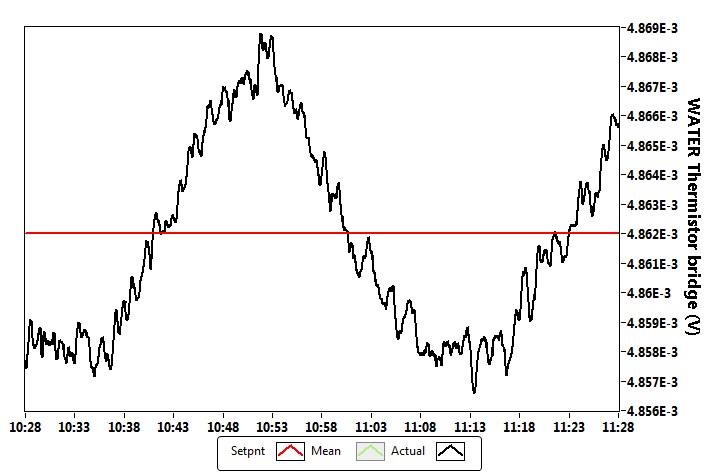
The sensor is a thermistor bridge, this bridge is driven with an accuracy of 5V reference (http://www.voltagestandard.com/New_Products.html). The output of this bridge is connected to a nanovoltmeter Keithley 2182. My LabView PID control (I bought the PID toolkit) drives a current source Keithley 2400 which is connected to a water - air heat exchanger Peltier solid state. On the side of this heat exchanger air is at a controlled temperature of the cabinet (air temperature stability is +-0.02 Celsius). The thermistor Bridge gives a signal of 50 mV/Kelvin to the excitement of 5V.
I have attached a photo where you can see measurement of a time data (sampling rate of 1 Hz). In general, I have a stability +-3rd-6 volt (standard deviation), which corresponds to the stability of Kelvin +-6-5.
I've set this PID command with the Ziegler-Nicholes tuning protocol standard, then first that I brought the stable oscillation system, and I measured the ultimate period time (1.375 minutes), and the nec plus ultra (147). The table Z - N gave to these values the following PID parameters:
P = 86.47
I have 0,687 min =
D = min 0,171
Overall, I am satisfied with my temperature control, but I'm looking for advice how to remove the visible oscillatory effect. This oscillation has a period of about 30-40 minutes, as you can see in the picture.
Is there something I could try to make my even more precise control? (it is also possible that I'm already at the possible gate given by the structural limits...)
Thank you very much!
Martins wrote:
Is there something I could try to make my even more precise control? (it is also possible that I'm already at the possible gate given by the structural limits...)
Can trace you to the output of the control loop (the value being written to the power source)? Specifically, draw out of the Keithley (if available), since the PID algorithm can output values with a finer resolution the Keithley can generate; Otherwise, around the PID output to match the resolution of the Keithley. See if the current alternates constantly between two specific output values, or if the output is continuously evolving during the swing.
What I think is happening, is that you have reached the limit of resolution of the power source, in this case, it will be difficult to eliminate this oscillation using PID, because the current source cannot output the exact value that you would allow to maintain the equilibrium temperature. If it does, the output changes between the two values from the nearest exit of you and you will always have a swing. You can try to increase the full gain (reduce integration time) to see if you can get a faster response and reduce the amplitude of the oscillation, but the trade-off is perhaps more great overtaking when you change the set value.
-
I'm getting to do a settings editor window that has several groups of settings that can be edited and saved. The settings are loaded and saved on a Bay of clusters. The window uses a shift register to store all changes and then you can save at the same time when you are ready. The problem I see is that if I change a value and leave the cursor in the control, and then a new group he will not read this new value. I understand that you should put the control that you want to play in the same event, but the problem is I want to be able to read this control with several events and it makes sense to have the control outside the structure of the event. I have attached a sample vi of what I am trying to accomplish. I'm relatively new to labview and learning I'm leaving, so any help would be appreciated. Thank you
-
How to create the Webservice data control with a secure Web service?
I am creating a data control with a Web service that requires authentication (SSO)
There are two ports for my server OC4J 7777 (requires authentication) and 7779 (authentication is not required).
(The service Web application is deployed in OC4J)
I am able to create a data control with port 7779 not, but I'm not able to create with the port 7777. In my app, I'll go "user email" the SSO. I require it a data control with authentication. How to pass the user name and password when creating the data control? I'm not able to go "Point endpoint authentication" stage also. I get the error message "the WSDL document is not found" when I type the URL in the first step.
I created the data control with port 7779 and after I modified the 'DataControls.dcx' file with port 7777. (IE "wsdl ="http://ipaddress:7777/../..?WSDL"), but I do not get the appropriate data.
I work with JDeveloper 11.1.1.0.0g
Please help me,
Thanks in advance
VinodThere was a few bugs in this area, who are already fixed in our current code line, then they should do it in the next version.
-
by using labview co-simulation, how to control the PWM market factor in multisim
I am new to the use of Multisim with LabVIEW using co-simulation. I would like to ask if there is a PWM component in Multisim, which can have its cycle have to be controlled using LabVIEW? I have an algorithm in LabVIEW that returns the duty cycle values between 0 and 1, representing the percentage of duty cycle.
How can I control the PWM market factor in Multisim using LabVIEW co-simulation?
Thank you very much
SPECTRUM
Hi spectrum,
In Multisim, find items based on functionality, there are some PWM models in the database. Take a look at this knowledge base if you don't know how to search for parts:
http://digital.NI.com/public.nsf/allkb/7309A5CABC677296862577ED006EC99E
Also, take a look at this knowledge base:
http://digital.NI.com/public.nsf/allkb/EF391C48CF71AE4F862571B900644F84
This article shows you how you can get Mutlisim and LabVIEW to co-simiualte:
http://www.NI.com/white-paper/13663/en
I hope this helps
-
Problem setting up an encoder input and PWM output tasks on CompactDAQ
I use a chassis with a modules 9474 cDAQ-9174 and 9411. I do not think it is important, but they are the cRIO-XXXX modules NOR old provided with a test configuration that has been distributed to early adopters. I use DAQmx tasks in an application (C libraries) to read (angular position) quadrature encoder and drive a motor directly with PWM current (pulse output). For various other needs, my tasks Setup is as follows:
[DAQmx] MajorVersion = 9
MinorVersion = 2
[DAQmxChannel venture 9411 wheel entry/AngularPosition]
CI. AngEncoder.PulsesPerRev = 500
CI. AngEncoder.InitialAngle = 0
CI. Encoder.ZIndexVal = 0
CI. Encoder.ZIndexPhase = a Low high B
CI. Encoder.ZIndexEnable = 0
ChanType = input meter
CI. MeasType = Position: angular encoder
CI. AngEncoder.Units = ticks
PhysicalChanName = cDAQ1Mod2/ctr2
CI. Encoder.DecodingType = X 4
[DAQmxChannel venture 9474 PWM output/PulseOutput]
CO. LTD.. Pulse.IdleState = low
ChanType = output meter
CO. LTD.. OutputType = Pulse:
CO. LTD.. Pulse.HighTime = 5.0000000000000004E - 006
CO. LTD.. Pulse.LowTime = 5.0000000000000002E - 005
CO. LTD.. Pulse.Time.InitialDelay = 0
CO. LTD.. Pulse.Time.Units = seconds
PhysicalChanName = cDAQ1Mod1/ctr3
[DAQmxTask venture 9411 wheel entry]
Channels = venture 9411 wheel input/AngularPosition
SampQuant.SampMode = continuous samples
SampClk.ActiveEdge = Rising
SampQuant.SampPerChan = 100000
SampClk.Rate = 100000
SampTimingType = sample clock
SampClk.src=/cDAQ1/100kHzTimebase
[DAQmxTask venture 9474 PWM output]
Channels = venture 9474, output PWM/PulseOutput
SampQuant.SampMode = continuous samples
SampQuant.SampPerChan = 100000
SampTimingType = implied
RegenMode = allow regeneration
[DAQmxCDAQChassis cDAQ1
] ProductType = cDAQ-9174
DevSerialNum = 0x18B3EC0
[DAQmxCDAQModule cDAQ1Mod1]
ProductType = NOR 9474
DevSerialNum = 0xDEDF40
CompactDAQ.ChassisDevName = cDAQ1
CompactDAQ.SlotNum = 1
[DAQmxCDAQModule cDAQ1Mod2]
ProductType = NOR 9411
DevSerialNum = 0xDEDB24
CompactDAQ.ChassisDevName = cDAQ1
CompactDAQ.SlotNum = 2
Each task works fine on its own (i.e. without the other). The problem is that if I start the task of the encoder first and then the task PWM, the latter causes an error:
Error-89137 occurred to the DAQ Assistant
Possible reasons:
Specified route can not be satisfied, because it requires resources that are currently in use by another route.Source device: cDAQ1
Point source:
80MHzTimebase
Destination device: cDAQ1
Destination
Terminal: Ctr3SourceNeed for resources in use by Source
Feature: cDAQ1
Terminal of source: 100kHzTimebase
Destination
Feature: cDAQ1
Destination terminal: Ctr2SampleClockThe task name: _unnamedTask<61>
I don't know why this is, but if I start the PWM task first, and then the task of the encoder, it also works. I should also mention that initially I was using counter 0 encoder, which caused a shift in the 100kHzTimebase to Ctr0SampleClock, which, according to the ways of device 9411, is not supported. Yet it worked (in itself). I wonder if this is happening under the hood isn't quite what is shown.
What is exactly the conflict and what can do to avoid it? The reasons for having to use specific modes and the settings (for example, the 'continuous samples' with 100kHzTimebase clock) are rooted in various performance and requirements of optimization that were created in a previous version of our software, so I prefer not to take a completely different path, if some small changes would lead us to correct the problem.
I appreciate your help.
Kamen
Hi Kamen,
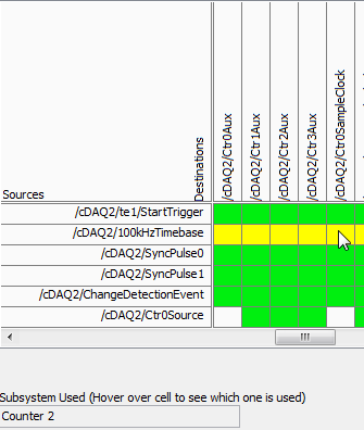
The time base of 100 kHz is not a direct route to the counter sample clocks, the device actually uses one of the other counters to complete the road (the routing table is a little misleading here because it shows 2 meter that one always doing road - in fact it will be any available counter):
So in your case, when you start the task of the encoder, it uses one of the other available counters to complete the configured road (100 kHz to ctr2 sample clock timebase). Of course, she chose meter 3.
Possible workarounds (looks like you have already found one yourself):
1 start the PWM before the task of the encoder task - if the task PWM starts first the counter is already booked and the task of the encoder would choose another available counter to complete its road.
2. explicitly reserve the PWM task before you begin the task of the encoder (if you need to start the task of the encoder first).
3. use cDAQ1/_freqout to generate the clock sample 100 kHz signal and use this instead of routing to the time base of 100 kHz to the counter sample clock.
Change autour counters should also work, but I'm not 100% sure how the unit selects which counter to use for routing (I don't expect change in the future, but if it's not explicitly spec'ed somewhere so I wouldn't take my chances)-if it were me, I would choose one of the other options above.
Best regards
-
Hello world
After 10 years of LabVIEW experience I'm totally lost.

It's my first project with DAQmx and I do not know how to handle.

My configuration: Windows7. LabVIEW 2012 DevSuite; X Series USB-6366
My goal: trigger value encoder and 2 inputs analog
I would get a result for the value of the encoder and each of the two analog inputs for each change of the value of the encoder (not more! I do not want to sort a huge amount of data afterwards)
I was able to configure it with the measurement and Automation Explorer, but have no idea how to do that in a LabVIEW configuration.
Read all of the examples I could find the analog inputs and the encoder with SampleClock. This isn't what I'm looking for.
I would be very happy if someone could guide me to my solution.
I have attached the confiuration exported from the measurement and Automation Explorer.
Thanks in advance, best regards,.
Balze
P.S.: Sorry I got COMPRESS the *.nce file, because NEITHER allows you to attach files *.nce

You'll get there, but yes, the first exhibition to DAQmx is probably a little overwhelming. A few other tips based on your screenshot (I'm on LV2010 & can't open the code).
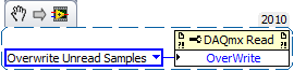
1. "allow buffer overwrites" is that a functional but description is not text. It lies under the Read DAQmx property node and must be configured before starting the task. Here is an excerpt:
2. it is usually (but not always) an available timing system to be used for all HAVE channels in a task just by the material. As a result, all channels to HAVE should be included in a single task. You can do this easily in chaining your call 'DAQmx create Virtual Channel' twice the job output and input/output error. Because the second call will receive a task refnum as input, it will configure the 2nd channel of AI to be part of the same task.
(It is possible to specify just several channels in a single call, but separate calls gives you the ability to configure different setting on the scale or range of entry).
3. the 'random', which IA task gave you the error is due to the lack of sequencing in your attempts to start tasks. The question which is the fortunate success that happens to run first can (and does) vary from run to run. By combining the two channels to HAVE in a single task, this problem will disappear, but you want to be sure that the tasks of the AI and the counter are started * before * any clock signals come to PFI8.
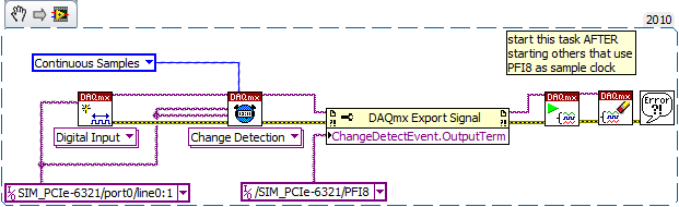
4. "change detection" will be available for digital input assignments, not tasks of meter. And it is also generally supported only for a digital port a-bit value. Other ports then that support data acq clocked by the software on demand. I guess one of these questions is the source of your error.
On the boards of the M series that I used, change detection has been supported only on port 0 - I think that the same thing will be true for the X-series cards. The following took place without error for me using a simulated X series device. By selecting another port gave an error.
Maybe you are looking for
-
Firefox button does not work since the installation of 16.01 for win7 64-bit.
Even if the button does not appear, there is no answer to the click of the mouse
-
My AS200 shows only 1 min clips on iphone
I was using my cam of action AS200 for thr first time yesterday. after shooting a bunch of clips in time modes film & loop (loop set to 5 min). I have connected my iphone 5 to watch and I got a bunch (about 30 or more) 1 minite long clips. I used it
-
How to upgrade a table after each iteration?
Hello I have a vi which works fine but the problem is that it updates all the data once the vi stops running. I want something as soon as (for outside for loop) 1 iteration it performs updates the table in front of the Panel, then 2nd iteration, it u
-
You try to run any .exe gets the pop-up message "Please select the program to run rundll32.exe.
Check on a friends computer; It can run internet explore unless she added as an administrator. you try to run any .exe gets this pop asking what program to run this title? It could be an association of .exe that is messed up, or is it probably some
-
HP 6500 709 has: will be printed computer, but does not copy the text to the glass screen.
I tried hard reboot as an Advisor by the forum without success. The copy starts pulling on the blank paper and stops with flashing orange on Panel saying "on paper." Turning the power off, ejects a regular sheet. I opened the back panel of the print