Lack of analog input/output range
Hello!
I LV 8.6 installed on my PC with XP OS and my card is 6024E. I noticed that the analog input/output palette is not appearing or missing. I tried searching but no luck. NOR-Daq traditional 7.4.4 currently installed.
Try reinstalling the device driver CD/DVD and make sure you have selected traditional DAQ.
Say you you installed NOR-DAQ 7.4.4. But if it was made before you install LabVIEW, LabVIEW and then see.
Tags: NI Software
Similar Questions
-
Multifunction analog input/output
I use USB X series 6356 to my experience. I send out a pulse of tone by analog output channel to an actuator.
And receive the signal of response of a sensor to an analog input channel. I've included a screenshot of VI.
The question is, I get the output of the signal response signal as well.
If I send (via the output channel), a burst of your 10 KHz which begins at t = 0.
I see that the tone burst into my plot of input channel as well (at t = 0).
Please, let me know if I use the good VI (I build it according to multi-multifunction-synch I AO VI of examples).
I use the loop to remove 60 Hz noise (by an average of more than 100 times) signal.
Hi Vishnu7,
From what you describe, it seems that you can meet with some ghosting or crosstalk on your analog input channel. Take a look at this knowledge base article and see if it matches with what you see.
http://digital.NI.com/public.nsf/allkb/73CB0FB296814E2286256FFD00028DDF
-
Triggers of analog input output meter with delay
Hello!
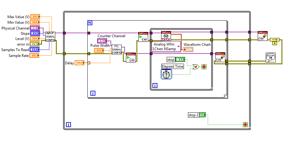
I am currently using a PCI-6251 DAQ card with a block of connection BNC-2120. I have a VI (one that is attached to this topic) that will essentially be an analog input signal and produce digital impulses from the output of the meter to each instant trigger. I am also able to define a series of delay values such that the delay will update automatically each at intervals specified by the user or when you press the stop button. I wonder if there is anyway to change this program as the time-out value will change every instant release. So, for example, in the first trigger a pulse is produced 0 second delay, then immediately when the next instant relaxation is reached, a push will occur with a 0.1 second delay, etc... And I want that the series of the time-out values to keep looping. I tried to use my current VI, with time to stop at each iteration to be less than half of the period, so theoretically it should go to the next delay value in the next instant trigger. Then I tried to put a certain time-loop around it to keep the job going, but it doesn't seem to work. I've attached a screenshot of my attempt, please let me know if this is possible, thank you! To see what each part of the VI in the screenshot, please see the screws attached, thank you!
P.S. for the VI that is attached, the analog input signal is 281Hz, the pulse width is 2.5% of the period and the delay is in the stages of T/20.
No worries,
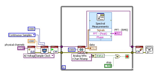
Please see the attached block diagram image. It is important to wire terminal on the Read.VI DAQmx acquire in a constant to the number ofsamples. This will force this function to wait until many samples are available in the buffer. In my example, you will get 1000 samples per second (because my rate is 1 kHz). and these 1000 were submitted directly to the FFT. What happened for example of you, it is only because you have not specified the number of samples to read, it is by default (-1), which means that the DAQmx Read.vi will pull all the data that is available in the buffer at the time. So if you had only 2 samples in the buffer that your FFT will have only two samples on average and as a result it will fail. Try this and it should help!
-
Limit NI9215 analog input voltage range
Hello
I use a NI9215 (mounted in a cdaq 9174) to acquire a voltage signal. I want to keep the tension as an integer and then later convert it to a voltage in the script of Fortran. To do this I need to know the relationship between integers and tension. If I use an unsigned integer I 0 is-10 for example (numbers aren't important as long as I know what they are).
I tried to taste a voltage signal (see the attached vi), where I have limit vmin and vmax at the return of V-10 and + 10. When I have a voltage outside this range, waiting for the signal to saturate at-10 or + 10 V, but this does not happen. I generally get +/-10.4 V which figure is the maximum range. This range would have been ok if it was exactly +/-10.4 V but it varies from something on the order of 0.5% between the different channels I use.
Is it not possible to set vmin and vmax that I'm trying to do and if so, what is then the point of vmin and vmax?
Concerning
PAL Egil
Hi pal_egil-
I guess you are trying to save time processor or (perhaps more likely) storage space by resizing the data yourself. I suggest that you use the version of DAQmx Read 'no'. This will give the most fundamental data type available and will save processing time (because it will not be scaling of tension and then re-scaling to an integer value simple on a linear scale of your application) and storage (because you will be able to store a single value of 2 bytes for each data point of your device).
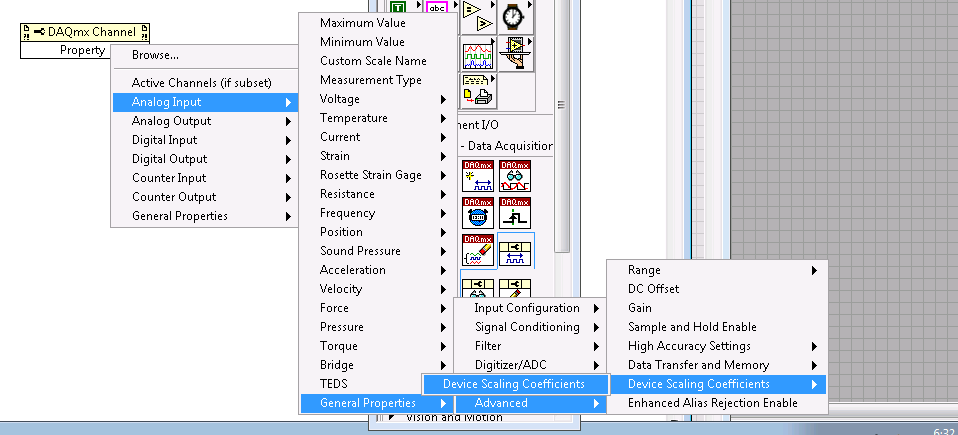
So these unadjusted nationwide tension later readings, you'll also want to connect the device scaling coefficients for your module. These are accessible from the property of DAQmx channel node in LabVIEW, and a description of how to apply them to lectures unadjusted using LabVIEW for NOR-DAQmx.
I hope this helps.
-
How to synchronize the analog input and the output of two different USB data acquisition boards
Hi all
I have two tips very different USB NI USB 6008 case, which I use to acquire the data (analog input) and a USB of NI 9263 is a output analog only site I use to route a signal (in this case a square pulse). The reason why I use the outputs analog 6008 is because I need to deliver negative tension and need the full +/-10 v range.
Looking at similar positions, I'm pretty sure that I can't use an external trigger or a common clock, I also tried to use the timed synchronization of the structures but no cigar.
I'm including a quick vi I whipped showing how the jitters because of the lack of synchronization signal. The OD of the 9263 connects to AI in the 6008 in this example.
I talked to a specialist in the phone and tols me that's not possible.

-
What is the minimum response of analog input, through DSP online, output analog time?
Hello experts!
I want to know if it is possible to get a very quick response latency (~ 1 ms) sound recording (analog input), through online registration (DSP online), the presentation of his (analog output) processing, by using the DAQmx programming codes. My system of NEITHER includes NOR SMU 8135, SMU 6358 DAQ Multifunction controller and SMU 5412 arbitrary signal generator. I also have access to the latest version of Labview (2015 Version) software.
My project is on auditory disturbances, which inovles record vocalizations, manipulating the recorded vocalziations and then present the manipulated vocalizations. My current idea of how to achieve this fact triggered output voltage after reading the input using DAQmx Read samples. DAQmx Read output is filtered online and then passed as input for the DAQmx writing for analog output. For purposes of illustration, examples of code are presented below. Note for simplisity, codes for the trigger part are not presented here. It's something to work in the future.
My question here is If the idea above should be reaching ~ 1ms delay? Or I have to rely on a totally different programming module, the FPGA? I am very new to Labview so as to NEITHER. After reading some documentation on FPGA, I realized that my current hardware is unable to do so because I do not have the FPGA signals processing equipment. Am I wrong?
Something might be important to mention, I'm tasting with network (approximately 16 microphones) microphones at very high sampling rate (250 kHz), which is technically very high speed. Natually, these records must be saved on hard drive. Here again, a single microphone is shown.
I have two concerns that my current approach could achieve my goal.
First, for the DAQmx Read function in step 2, I put the samples to be read as 1/10 of the sampling frequency. It's recommended by Labview and so necessary to avoid buffer overflow when a smaller number is used. However, my concern here associated with the latency of the answer is that it might already cause a delay of 100 ms response, i.e. the time to collect these samples before reading. Is this true?
Secondly, every interaction while the loop takes at least a few tens of milliseconds (~ 30 ms). He is originally a State 30 late?
Hey, I've never used or familiar with the hardware you have. So I can't help you there.
On the side of RT, again once I don't know about your hardware, but I used NOR myRIO 1900, where he has a personality of high specific speed for the RT where I can acquire the kHz Audio @44 and process data. Based image processing is ultimately do the treatment on a wide range of audio data you have gathered through high sampling frequency and number number of samples as permitted by latency, please check this .
I lost about 2 weeks to understand host-side does not work and another 2 weeks to understand the even side of RT does not work for online processing (real time). Then, finally now I'm working on FPGA, where the sampling rate is 250 kHz (of course shared by multiple channels).
The complex thing with FPGA is coding, please check if the filter you want is given below as labview automatically generates some codes of some filters.
Most of them will work in 1 SCTL IE if your target has 40 MHz clock algorithm will run in 25 ns. That's what I was looking for, I hope you

See you soon... !
-
Hallo,
I use the following system:
- OR PXI-1044 with controller NI PXI-8109
- OR PXI-2564 switch module to turn on the monitor of my test device
- Data acquisition multifunction NI PXI-6259 to measure the signal that responded to the questionnaire jump
The two cards are the same - PXI trigger bus. For both, PXI-2564 and PXI-6259 I use DAQmx to set the reading and writing of the channels.
Now, I want to measure the time between the digital output, my unit turns and the analog input, which measures the response of my system.
I can't do work by myself, please help me!
I thank Ludwig.
Hi Ludwig,.
If you can't give us any VI we have difficulties with to help you.
Because I Donat knowledge how your program is mounted it is not easy to know where you should enter signals.
Here's a question similar to yours:
http://forums.NI.com/T5/LabVIEW/best-way-to-measure-time/TD-p/178704
and 2 external links:
http://www.ehow.com/how_8698983_measure-time-LabVIEW.html
http://objectmix.com/LabVIEW/385152-how-can-i-use-LabVIEW-measure-time-between-analog-pulses.html
-
Problem with a digital output in the information of an analog input
Hello
I use a SCXI-1000DC module with a module of the SCXI-1600, SCXI-1531 module and SCXI-1163 module to receive an analog of an accelerometer signal and a digital signal.
I claim that the accelerometer is constantly monitored, and the output is on when I want to, by an impulse that I comand in labview.
I use a rate 25 k and a 12, 5K samples per channel on DAQmx Timing.I notice in DAQmx read, if I put a sample of hight by channel, the output is not there when I want to, and if I put a few samples per channel, I exit when I want to, but the program seems to be slow with the passage of time. I don't know how I can solve this problem!
I'm sorry for my English, and I hope you can help me.
Thank you
Silvia
Hello Silvia,.
If you ask a larger number of samples, the labview diagram will stay longer in the DAQmx Read function, so the while loop runs slowly, and the digital output is updated less often.
I suggest that you use 2 separate while loops: one for the analog input and the other for digital output, so that each loop might run at a different speed.
Best regards
-
6009 outputs digital and analog input synchronization
Hello
I work in a program NI 6009. I want to leds by car with outputs digital NI 6009. For example, leads first will be on until what 200 micro seconds then second led will be on up to 200 micro seconds, and then first of all led will be on up to 200 micro seconds. I'll take led with photodedector signals and connect analog output photodedector input NI 6009. I want to synchronize the outputs digital and analog input and separate the first and second led signals the analog input for NI 6009 channel. How can you do with NI 6009? Please ADV
You can not do with the USB-6009 case. Its outputs digital are software with a maximum speed of slightly more than 100 samples per second. The outputs can produce 200 microsecond pulses and cannot be synchronized with the analog input.
You need a device with outputs digital hardware timed or counters that can produce a pulse outputs.
You can synchronize a bit digital output and analog input recording signal on an additional channel to HAVE. Will allow you to see the photodetector and LED the drive with the same schedule and such resolution as described by the sampling rate I. The maximum sampling frequency of AI on the USB-6009 case is 48 kHz that is shared by all channels. If you have two lights to led and photodetector two signals maximum sampling rate would be 48 kHz/4 = 6 kHz which is barely fast enough for your 200 US signals. For more than 4 channels, it won't be fast enough.
I suggest a simple oscillator circuit building and use it to clock a flip flop. This will give you alternating signals to drive the LEDs. You can use a line to reset the flip flop to give you control without the need for high speed.
Lynn
-
9174 triggered output pulses and analog input synchronization
Hello
I have a cDAQ 9174 with a 9215 analog and a 9401 module. I wonder if this configuration is suitable for my use: a trigger digital extern is sent to the system to trigger a task of analog input, trigger a generation of pulses, with another counter, count of trigger events. Using two counters on 9401, it seems I have no left Terminal at the entrance of my trigger signal. The trigger DAQmx vi does not show counters entries in the list of signals; and if I select a PFI line, an error that says that the line is already in use..., I missed a few obvious solution? I have change my 9401 to a 9402 did?
Thanks for any help,
Vincent
Hi Vincent,.
So, looks like you need a single line to use as input to trigger events and another line to use for a generation of pulse output. This should indeed be possible, since the 9401 has 8 lines that are configurable nibble (i.e. lines 0:3 could be configured as inputs, while the 4:7 lines could be taken out, or vice versa).
However, a big caveat with the 9401 is that the lines must be reserved before each task is started. This is a limitation of the direction of the line is implemented in hardware and is common as customers when something they using the 9401. Explicitly reserving your tasks before starting must correct the behavior if that is indeed what you see.
Best regards
-
MULTIFUNCTION CARD analog input 4, 4 meters, 16 outputs analog
Hello
I am looking for a card of this product with the following features data acquisition,
- At least 4 meters
- At least 4 analog inputs
- At least 16 analog outputs
- PCI or PCIe or USB
Can someone give me an idea on the map OR equivalent specifications.
What will be the effect on the acquisition of data if I use two differernt cards? for example if you meter, analog output on a single card and entered only analog on the other card. Be it the questions of time between two cards over the selection of software such as LabView? especially when all the dry milli is very important for you.
Kind regards
WAQAR
You might want to watch a cDAQ chassis.
1. all the new cDAQ chassis have 4 counters on the backplane. They are accessible through any module "parallel" (essentially no matter what digital IO module with 8 lines or less, 9401 or 9402 are fairly standard according to the desired connector type).
2. There are a variety of analog input modules available for compact data acquisition - you can select based on your application (sampling frequency, precision, conditioning, etc.).
3. for the 16 analog outputs, you probably want to use a 9264.
4. the 9174 or 9178 use USB and have 4 and 8 slots for modules respsectively.
Best regards
-
Toggle the analog inputs and tasks of output on the same card in LabView
Hello
I'm relatively new to LabView and am trying to find the best way to switch between reading and writing tasks on my PCI-6024E. It seems this would be a common thing to do, but I found no good documentation or any relatable example program. Basically, I would like to be able to monitor certain analog inputs and then write that some outputs if an entry is in accordance with certain specific conditions (say > 4 Volts voltage). It is my understanding that you can only signal (input and output) types associated within a single task in DAQmx. I also understand that you cannot have multiple tasks running at the same time on the same material/map, otherwise you get a: 50103 error 'The specified resource is reserved. Calendar is not really all that matters to me, but quite synchronous and effective would be nice.
I have attached a sample program that shows more or less what I'm trying to do. I want to follow several analog input lines (AI0 AI1, AI2 and AI3 and) effectively at the same time. If certain conditions are met, AI3 > 4 Volts, then write 5 Volts for analog AO0 and AO1 outings. I also want to maintain output at 5 Volts up to AI3 falls below 4 Volts. Is there a better way to pass the task to read and write than what I've done here? In a sense, all I really do is toggle of a state machine if the required conditions are met and if start/stop tasks of reading/writing necessary.
One last question, is there a way to display the four channels in the waveform graph using the 1 d NChan 1Samp mode so I can have a time chart and indicators?
P.S. I'm under LabView 2011 on Windows 7. Your ideas and suggestions are appreciated.
Thank you
KJ
I also understand that you cannot have multiple tasks running at the same time on the same material/map, otherwise you get a: 50103 error 'The specified resource is reserved.
This is incorrect. You can't have two tasks of the same type running on a single card. You can have an analog input and analog output task running simultaneously on the same hardware.
You are right that each task can have only one type of task (entry or exit). Discover DAQmx examples in the example Finder to get examples of synchronized input and output.
PRO TIP: In the Finder of the example, go to the drop-down list in the lower left corner. Pull down and select Add Hardware. In the pop-up window, add your PCI-6024E to the right pane. Click OK in this window. Then in the main window of Finder example select your hardware from the drop-down list and check the filter results by the hardware. The example Finder then only you will show examples that are out-of-the-box compatible with your hardware. I am sure you can find something to fit your needs here.
-
Hi all
I'm starting my first app using a card of RIO for the analog input and power (two PCI-7833).
My previous experience with DAQ systems was on PC so I'm especially familiar with DAQmx. It is my understanding that DAQmx is not really being used on these boards, there is no DAQmx tasks to play with.
So, my question is this: How can I dynamically set the range of the signal of the analog inputs so that I get the best possible resolution?
What I want to say in DAQmx if I know that the input signal is only 1 V pk to pk I can put this beforehand in the task.
Thank you!
OK, a little further digging shows the input range is set to +/-10V, is this correct?
-
Output TTL triggers analog input with PCI-6251
Hello, I'm new to LabVIEW and have a question that I hope I can get a response on this forum. I am currently using a PCI-6251 DAQ card with a block of connection BNC-2120. I would like raise an event on an input, for example a sine wave, which is connected to AI0 analog. Then I would send a TTL pulse train via the digital output. What I'm describing can be better understood by the images of this link:
http://zone.NI.com/DevZone/CDA/tut/p/ID/3017
In the tutorial page linked above, they do mention the card PCI-6251, but when I read the specs and compared, 6251 also has analog and digital Board, trigger functions, as well as digital I / Os... so I think he should be able to do what I want it to do. Can anyone confirm this? If anyone could help me by providing a VI that could do what I ask, just to help me get started, would be greatly appreciated. Thank you!
Hello!
Please post on the Forums OR! My suggestion would be to use build it digital Pulse - Retriggerable.vi found in the Finder for example of OR. Open LabVIEW, go to help > find examples > input/output equipment > DAmx > generating digital pulses > generate digital Pulse-redeclenchables. Change the type of trigger for this departure vi > Analog edge and make the source one line APFI (pin 20 of your card is APFI0). This will generate a pulse based on an edge similar to a level that you specify.
I hope this helps!
-
How do I get the analog input signal and send it to output analog (real time)
Hello world
I do a simple task in Visual C++ and I use PCI-6221(37 pin).
Basically, I want to send the same signal of "analog input" to the "analog output".
at the same time (or almost), to make real-time application.
Can someone provide me with sample program please.
I would be grateful if you could provide me with the great tutorial that explains
step by step everything about NOR-DAQmx for C/C++ programming.
Best regards
Khassan
This is my code in C++, you can optimize it if that seems too messy. This code reads the analog input signals and exports it through the analog outputs.
To make this code additional work of the directories include and library directories must be added to OR.
I hope it helps someone.
#include
#include
#include "NIDAQmx.h".
#include#define DAQmxErrChk (functionCall) {if (DAQmxFailed (error = (functionCall))) {goto error ;}}
int main (int argc, char * argv [])
{
Int32 error = 0;
TaskHandle taskHandleRead = 0, taskHandleWrite = 0;
Read Int32 = 0;
float64 context [1000];
char errBuffRead [2048] = {'\0'};
char errBuffWrite [2048] = {'\0'};
bool32 done = 0;
Int32 wrote;DAQmxErrChk (DAQmxCreateTask("",&taskHandleRead));
DAQmxErrChk (DAQmxCreateAIVoltageChan(taskHandleRead,"Dev1/ai0","",DAQmx_Val_Cfg_Default,-10.0,10.0,DAQmx_Val_Volts,NULL));
DAQmxErrChk (DAQmxCfgSampClkTiming(taskHandleRead,"",100.0,DAQmx_Val_Rising,DAQmx_Val_ContSamps,0));
DAQmxErrChk (DAQmxCreateTask("",&taskHandleWrite));
DAQmxErrChk (DAQmxCreateAOVoltageChan(taskHandleWrite,"Dev1/ao0","",-10.0,10.0,DAQmx_Val_Volts,NULL));
DAQmxErrChk (DAQmxCfgSampClkTiming(taskHandleWrite,"ai/SampleClock",100.0,DAQmx_Val_Rising,DAQmx_Val_ContSamps,1000));DAQmxErrChk (DAQmxStartTask (taskHandleRead));
DAQmxErrChk (DAQmxStartTask (taskHandleWrite));While (! fact &! _kbhit())
{
DAQmxErrChk (DAQmxReadAnalogF64(taskHandleRead,1,10,DAQmx_Val_GroupByScanNumber,dataRead,1000,&read,));
DAQmxErrChk (DAQmxWriteAnalogF64(taskHandleWrite,read,0,10.0,DAQmx_Val_GroupByChannel,dataRead,&written,));
}
_getch();Error:
If (DAQmxFailed (error)){
DAQmxGetExtendedErrorInfo (errBuffRead, 2048);
DAQmxGetExtendedErrorInfo (errBuffWrite, 2048);
}
If (taskHandleRead! = 0){
DAQmxStopTask (taskHandleRead);
DAQmxClearTask (taskHandleRead);
}
If (taskHandleWrite! = 0){
DAQmxStopTask (taskHandleWrite);
DAQmxClearTask (taskHandleWrite);
}
If {(DAQmxFailed (error))
printf ("error DAQmx: %s\n",errBuffRead); ")
printf ("error DAQmx: %s\n",errBuffWrite); ")
}
printf ("end of the program, press the Enter key to quit\n");
GetChar ();
return 0;
}


Maybe you are looking for
-
After updating FF 8 fonts appear too small
What happens on almost all websites. Of course I can increase the size of the characters with ctrl-+ but this also increases the size of the image on this page. Clearly, the fonts are too small. The difference can be particularly noticed with combobo
-
The Apple on Windows software update
Does anyone know how to fix Apple software update for windows told me to check my internet connection, but my internet connection, so that no one knows how to fix it?
-
HP G71 recovering files once the motherboard is dead
My HP g71 mother died. I would like to get the files on the hard drive. The G71 primer not at all. No error but screen black nothing. If I get out the hard drive is a cart or stand that I can use to allow me to connect to the hard drive for my ur
-
Hello I want to install a WRT160 to an existing network. I'm on Qwest with their DSL modem. My network router's network 10.0.0.0/16 Vyatta. I know that the 160 is a router (must have purchased access point instead, my fault), so I placed its IP add
-
After a clean install of Windows 8, I can't get three monitors to work
I did a clean install of Windows 8 pro. I have a Dell T1500 with over-pants V4800 graphics. This machine previously had Windows 7 installed and works with the ATI driver. With Windows 7, the three monitors worked without problem. Now, with Window