Large signal output capacitance measurements
Hi all
I'm working on a power amplifier and I want to measure the ability to output under large signal condition. I use a non-linear model of the GaN power transistor.
Power output is about 36 dBm, f = 8.2 GHz
I tried both methods:
(1) I have spent under bias Vgs - 6V to 1V, Vds = 28V. I use solver C_PRC linear tab to find the parallel to the output capacity. I got a chart that changes from 0.3pF to 0.5pF. In this simulation I don't use tuner to impedance, just ports (50 ohm) and sources of bias.
(2) amplifier is biased to 28V and 125mA. Then, I drive amplifier with of 20dBm to 30dBm input power. In this simulation, I used HBTUNERs to maximum power output (power input 25dBm at the entrance) and the output. I can see there is a change in capacity at the entrance vs input power change. However, in the output, production capacity is constant and 0.52pF. I am able the ability of the drain of transistors, tuner. I use great Solver for the parameter measuring signal Y and calculate the capacity.
The interesting thing, I can meause entry changes easly to large signal capacity, but output capacity is constant!
I have two questions:
(1) why the three measures are different?
(2) for large signal measurements, for example; 30dBm output, 30 v peak-to-peak output average 40dBm 50 v peak-to-peak. So, there is a change in capacity over a period of time. When I measure the Solver big signal, Solver uses the high peak values? If so, can I change low peak value?
(3) can be used for important signals gamma probes?
Thank you
Tags: NI Products
Similar Questions
-
6733 continuous signal output generation.
Hello
I want to use an NI PCI-6733 map for generation of continuous signal output.
I downloaded the modules OR measure small DDK OR 671 x & 673 x examples (PCI & PXI) and run the samples.
Our goal is to put a few samples in the FIFO buffer and use the external update (on PFI5) to send the samples to the exit.
Essentially a combination of AOEX4.cpp and AOEX6.cpp example should work.
However, example 6 uses board-> DACDirectData0.writeRegister (.) to set an output value.
To update the output, I use the following code to generate a wave of block.
Sub
NIPCI6733Card: nPoll_Test_T6() / / function called at 5 kHz
{
t67xx * Council const = & GetNI();
Support * const theSTC = & GetSTC();////////////////////////////////////////////////////////////////////////////////////////////////////////////////////////////////
theSTC-> Joint_Reset.writeAO_Configuration_Start (1);
theSTC-> Joint_Reset.setAO_Configuration_Start (0);
theSTC-> Joint_Reset.setAO_Configuration_End (1);
theSTC-> Joint_Reset.flush ();
////////////////////////////////////////////////////////////////////////////////////////////////////////////////////////////////Board-> DACDirectData0.writeRegister ((OutputHigh). 0400:0 x 0 x 0);
Board-> DACDirectData1.writeRegister ((OutputHigh). 0400:0 x 0 x 0);
Board-> DACDirectData3.writeRegister ((OutputHigh)? 0100:0 x 0 x 0);OutputHigh =! OutputHigh;
}
My frequency of update of application (the election) is 5 kHz. The output should run on 15, which means that each update I need to resolve before the 3 samples. I want to use FiFo for this.
(Note: the output is triggered by PFI5 at 15 kHz)
My idea is to 3 samples in the FiFo buffer each update of the application and leave the external trigger update of the output.
Example 4 uses the FiFo. However, this example stops after 5 running running the same fifo data.
How can I set up FiFo continuous data?
370735e.PDF manual describes the following:
With non-regeneration, old data will not be repeated. New data should be
continuously written to the buffer. If the program don't write new data to
the buffer at a speed fast enough to deal with the generation, the buffer
will be negative and cause an error.This is what I want. Is there an example?
Kind regards
Peter
Dennis,
Thanks for your reply.
I have whil post-its on the correct Board.
I implement for IN-Time. It is a time real OS for Windows.
Kind regards
Peter
-
Dear all,

I want to record and output data with two separate cards (later synchronously).
For data acquisition, I use the NI PCI-6133, for the data output, the NI PCI-6733.
The data collection works, but there are problems with the data output. In the first ms the desired signal (eg. Sinusoidal 25kHz, 1V) is issued, but after a certain time a sinusoidal output with about twice as high frequency occurs, the actual signal occurs only sporadically on.
The desired and undesired signal seem arbitrary to change. In addition other frequencies were tested which attain the same result.In the appendix of the current code, and some recording of the problem (with the PCI-6133 & oscilloscop measured). Can anyone explain the error?
Personally, I think that the first step is to remove the Structure of sequence - it is absolutely not necessary (you use correctly the wire of the error to serialize the main steps of the data stream). It becomes big, bulky on the block schema structure will allow you to "reduce" it to a more reasonable size.
Here are a few questions and comments.
- You have a current activate button, you seem to be set up a channel of AI voltage (not a current AI).
- Why is the function AO Start Task in a "First Call" Case statement? According to the block diagram, it is not in a loop, so it has the first appeal and the Case statement is not necessary.
- I did not AO output waveform, so I won't comment on the loop of the AO.
- I have done HAVE sampling. Why you have a Stop function and clear the tasks inside the loop? Only after acquiring the data? [I think you have to put these two functions and the error handler, outside the while loop].
- By putting them HAVE and AO in the same loop, you are forcing them to run at the same time. If that's what you want to and if they have the same time 'cycle', and if there is enough "free time" for all other calculations that you have to do inside the While loop with a loop may be OK. Especially if they are cycles at different rates, you should have them in parallel while loops.
Looking forward to Version 2. Try to get as much of your diagram of block on a single screen as possible. Do not hesitate to 'hide details' in under face.
Bob Schor
-
Signal output data expressed on a serial port
Hello everyone,
I received a task which requires me to collect several channels in express signal analog voltages before displaying these data to the serial port of the computer. My programming experience is very limited as Im working on the back of the high school before going to College, and even though I have the foundations of basic labview stowed, Im struggling to understand how to approach this problem.
I started looking at the base read the series and write vi provided in the examples and I know how to get labview vi to intergrate with signal on purpose, but because of my lack of knowledge related to the use of channels of communications, binary, hexadecimal and asqui I don't really know where to go from here. The writing and reading of strings for example, I don't understand.
I would like the data are ideally output on the serial port in real time and data are collected continuously at 6 kHz.
I realize that there probably is no simple answer to this question, given my lack of knowledge, but any help would be greatly appreciated!
Thank you!
Harry
Hi hcook,
As smercurio_fc said, the strings that you send are totally dependent on what you're talking about. I haven't used a 'box of dspace' before, but a normal serial device will wait to receive specific orders. Once it receives an order of some, she will perform a certain task. You are right in saying that you need to establish what string commands to send to the box of dspace.
You can find these useful:
General concepts of Serial Communication
Overview of Serial CommunicationI hope this helps.
-
How to convert data from XY graph for type ' signal in "for measurement functions
Hi all, I have a driver file that generates the screenshot XY graph. I want to measure the period, using the measurement functions in the LabVIEW palette. Can someone tell me how to convert this type of signal "in". The X (time) and Y (power) are all there, but it causes an error when I son together?
Please see my attached code.
Thank you
Its ok people, I found a solution. See attached FYI.
-
Hello, I'm trying this arbitrary signal by arbitrary simulation of output signals express VI. I want an exit point out analog of the DAQ USB 6281 every second. When I said to output a point by iteration I get error 200609 say the selected buffer size is too small (selected the size of the buffer: 1, minimum buffer size: 2) how can I change the buffer size? attached if my VI, just go under the 1 'arbitrary' case and you'll see my VI Express with points iv series.
But you are passing an array many points so you should have to index this table point by point by putting the DAQ Assistant, in a loop with a delay of 1 sec. You can also spend the whole wave and specify a frequency of 1 Hz in the DAQ Assistant.
-
Voltage offset problems with the NO-9401 for PWM signal output
I try to create a 20 kHz PWM signal to drive a motor control circuit uses the NI 9401 module in the chassis OR cRIO-9073. Generating the PWM signal works. For some reason, changes in shift of power as the market factor is increased. It is less effective for the engine, as you can imagine.
The code I am using is the finder of the example, for the generation of PWM on an FPGA and is attached.
I thought that it worked before but may have used the the NOR-9505 rather PWM output to test my circuit. It would be unreasonable for me to do this as a permanent solution.
The problem can be summed up as: with an increase in the liability of the cycle the voltage line (offset) movement of the output signal in the negative (according to ADGE) Basic or down. The Vpp signal is correct and does not change. Against ticks from 0 to the maximum of 2000 ticks (duty cycle IN), the offset voltage shift is such that 100% the level of full voltage is 0V.
Any ideas as to why this offset voltage shift that happens?
Do not be dismayed, I worked on the problem. There was a connection problem - I thought I was logged in as reference Earth, but it has not been properly clipped.
-
How do I create free of glitch signals output in the buffer permanently changing?
Hi, could you point me to the example more suitable for the following cases:
I read and write digital and analog data at a rate of 5 kHz. At this rate, I need read and write samples N at a time and can point single bed and wrote. I want to assure you that my output is glitchfree, then, how to grow the next N samples to the DAQ (PCI-6221) card before it has finished writing the previous samples of N? This would ensure that at the time he was finished with the stamp of the previous, it will continue with the next buffer without missing a clock.
I can't use a blocking writing or interrogate the task when it is at the point where I managed to write the next N samples a clock or two would have passed.
Any ideas?
Hi AnthonV,
What you have described so far, I think the following example of the expedition would be a good starting point:
Help > find examples... > input and output material > DAQmx > power >
Gen CONT tension Wfm - Int Clk - no Regeneration.vi
The main idea is to define the task to continue (but not to allow the regeneration of the buffer). Data are written continuously in time loop then the task is still running, so as long as your loop may follow the generation that should do what you need.
If you have any questions about the example do not hesitate to ask. Thanks for posting and have a great day!
-John
-
No audio signal output windows 7 SR1629uk
I installed Windows 7 on my Presario SR1629UK desktop computer. Soumd icon shows "no audio output device is installed. It is installed and works OK on the victory. XP. HP does not have a driver for Win. 7 can help anyone.
Hello:
See if the driver directly from Realtek works.
Accept the agreement, download and install the file first or second as there is (32 or 64 bit).
-
No audio signal outputs H264 mpeg-based original
Hello
This has happened twice now, and I'm not sure this that cleared before
I created a video using 'The match sequence settings' and created an mpeg file that has audio. If I automatically (using the my watchfolder option) or manually, by dragging in the SOUL create a wmv or H264 version, they have no sound!
Any ideas?
I use CC on a PC windows with a card NVidea FX3800. CUDA as renderer
I think that if I export stright to H264 for the Organization, which works very well
Thanks in advance
I can confirm this as well, more the workaround solution that moves the MPEG file allows the audio to be recognized. I think that the cause is a XMP metadata file that is created in the same directory. If you delete the XMP file before adding the MPEG file in the queue of the SOUL, it also fixes the audio.
Good find!
-
Error memory for large records output:
Hello
My workflow process takes as input a list. He travels the workflow for all items in the list. If my list contains 4 items, there will be 3 * 7 = 21 stages when I invoke the process. I can check my recordings for debugging.
If I give 5 entries, it takes about 5 * 7 = 35 steps of the Workflow. If I try to play the record, I see the error: java heap space: out of memory exception. I've changed my space to Xmx1024m in workbench.ini. I also did: java - Xms < initial segment size > - < maximum segment size > Xmx (Q1: do we need to restart the JBoss after we do the second step?).
Q2: My system is Windows7 with 4 GB of RAM. I have liveCycle 8.2 with SP2. JBoss and MySql. I set this size of RAM to java in one of our JBoss server files?
Q3: Is there any file to set the maximum eligible steps for a process record? In the affirmative, please let me know. It would be a great help.
Thank you
Chaitanya
If you are certain that your service is enabled and works I don't know why the configuration settings would be disabled. The settings described in the sent link previously have been referenced in the documentation of the ES2, I have not determined if these 2 settings really existed in version (8.2 SP2) you have. Aside from that they wouldn't be useful if the OOM error took place on the server and not Workbench. As you receive the error in the Workbench there's a switch workbench.ini that you can add to limit the number of steps that will be loaded with a record:
-Dcom.adobe.workbench.unsupported.audit.maxNumberOfStepsToLoad = 250
The default value is 250, but you can try to reduce this value.
In addition, if the error is due to the size of your documents I don't know fo a solution for this but you can try making sure the variables view is closed when you load the recording.
-
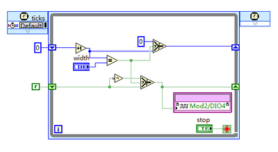
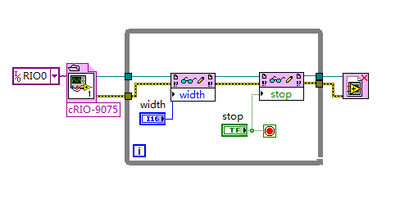
Why the output signal is pulled up to stop the program in RT
I use 9401 output a PWM signal. When I run the program FPGA and the stop, it does nothing statement. BUT when I run the program through RT using the compiled bitfile and stop, there will be a high level of 110ms.
Here's my diagrams FPGA and RT of a simple signal output.
I wonder why this could happen? Should I observe all specific during the programming of the RT?
Thanks in advance
You can add logic to ensure that the output goes low when the judgment is TRUE within your unique Timed Cycle loop. My guess is that you just see a delay between when the FPGA is ordered to stop and when the file bit is actually closed and the FPGA is reset.
-
serial port: input/output signal combined suburbs
I am currently using LabView to replace another user for a scientific instrument interface.
LabView is connected to this unit via a serial port. The instrument spread 25 bytes of binary data from the computer every second. I can read the binary string (Read VISA) and maintain will cause disc using a while loop. In addition, there are some instructions I can send to the device that will do various functions (start logging, turn the LED on / off, etc.). I can send these instructions to the instrument using the previous interface and in a stand-alone vi using VISA Write successfully, but when I place the function Write VISA in the largest interface vi, signals go haywire. Specifically, there are two separate lights I can alternate with two different commands, but when in the biggest interface vi, the two commands Toggle the LED even. In addition, it seems that the singal that immediately send to the instrument (a single ASCII character) bounces to the computer in the 25 bytes of binary data streaming. In other words, after I pressed the LED 'on' the key, a column of my streaming data changes when it's not supposed to (ex: after binary to ASCII conversion, changing a single digit in a 20 digit value).
At first, I thought that the problem was the sequence of read/write VISA. I read all the data in the current configuration, and then leave for orders writing. The two VISA functions are in the same loop to continuously monitor the data. Is it possible the signal output of writing not letting the while loop and being read as input? What would the instrument two different commands as the same as read? My goal is to run an interface that displays data in ASCII and allows some options different rocking while that the interface works - there is an elegant/effective way more as a while loop?
~ Going bananas
-
determine the angle of a complex signal phase
How can we determine/measure the amplitude and phase angle, separately, signal output complex in AWR in circuit level (schematic) design?
It depends on what you mean by complex 'signal': power, voltage or current? If it is a simulation of harmonic balance, you can use measures Pcomp, Vcomp and Icomp for value complex to a specific harmonic and choose 'Mag', 'Angle' (or "AngleU") as the modifier "complex" for the measure. This can be traced and then compared to what you are scanning. e.g. power, frequency, etc. If this does not answer your question, attach a copy of your project, or at least a photo; So we have some background.
-
Problem updating my state machine, using the emg signal
Hello
I have problems with my code. My entry is an EMG signal that I gather from three different electrodes using usb 6008. In the program, I divide the signals and display them in a chart that is unique. What I want now is to read the signal, and if a signal passes a threshold I want an LED lights. This must remain lit until there is another signal that passes the threshold.
To put it simply: "large enough signal--> lamp on--> stay informed--> enough large signal--> lamp--> stay off the coast and then start again."
I tried a few different approaches, but I decided using a state machine. Now, the problem is that when the signal to enter the state machine the program crashes. I think it's because the table that I use to convert the signals does not update when I get my state machine, so the signal stops to come. But how to get around this problem? It is even possible to code what I want?
I have attached the code. All the tips are welcome, I have been struggling with this for some time now.
Thank you
jenmich
The problem is internal while the loop is run until the stop condition is true, but he never does a new Boolean entry. So that it remains for always in the same State. Remove the inner loop and put the shift register on the outer loop instead.
You must also use a daqmx configures the element, and then set the properties of daq. The read.vi can be set to read a number of samples of each iteration.
Also: you can expand the table to index for several items of output. If you want that element number 0, 1, and 2, you have yet to wire the index entries

Maybe you are looking for
-
Bishop of HP 3105 m HP recovery question
So I just got my HP 3105 m and I would be satisfied, with the exception of the almost empty 4. ? Tools HP GB partition and the apparent lack of an Image reduced to this bloatware recovery option.(A) is the necessary tools HP partition? It's a strange
-
Lenovo U31-70 double tap on the touchpad does not work
Hello I just bought a new Lenovo U31-70 with Windows 10 already installed on it. There is a problem with the double tap feature, it does not work. The feature is enabled in the option. This model of Lenovo has Alps touchpad driver and I am not able t
-
I get a message WMS IDLE at stop down
Blocking PC, I get a WMS IDLE message, why I do this and what is it referring to I am running Windows XP Home Version, I have been using this version for 4 years. I recently updated my card mother and memory
-
Error code 0xc0000005 whenever I try to launch my programs,
.. as record cleaning tool, uninstall some programs (like 4sharedsync), open outlook. I don't know what to do? I have windows vista. I could get my outlook open in safe mode, when I opened my account gmail or yahoo, that I can not add attachments. Th
-
BlackBerry Smartphones, please allow us to change the shortcuts!
I have the BlackBerry Bold 9700 (which I love), however, I have a small complaint, the shortcut alt + del on SMS. If you press on these you lose any of your text. Now, I often write messages that are more than two or three long texts, for then all te