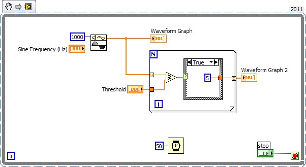
Limits of drawing on my wave form
I have two waveform graphs that display a live view of my oscilliscope.
What is the best way to draw two limits of amplitude on the axes Y Parallels? I can do this somehow property nodes? or do I have to do these multiplots of waveform graphs and add dimensions to my table-y?
Thank you...
You have 2 options (or more).
The second is by FAR easier than the first, but I'll show you both anyway
(1) build an array to a constant value, which would be your thresholds and draw as well as your data.
This will draw the boundaries above and below data is be postponed.
(2) create cursors. Nodes property allows you to assign their values are based on thresholds.
See the attached VI.
All the code in the while loop on top is option 1.
The ridiculously simple property node is option 2.
Tags: NI Software
Similar Questions
-
Hello
I am teaching LabVIEW. I want to delay a wave form and display it with the no delayed waveform. I used a delay in the examples. The output of the delay is thread (double waveform). Signal to simulate output is data Dynamics. My conversion of the thread (double waveform) Dynamics does not appear on the graph of a waveform. The VI is attached. Can anyone offer any comment.
It's displaying fine. The screen is hidden behind the screen of the second signal. Expand the Plot legend to display all three plots. Then toggle the visible property of the plot of the second and third plots.
Lynn
-
can not see the wave forms when dragging clips in the source monitor
I'm editing interviews where images and the original sound has been grouped in merged clips or sequences. I love the source monitor editing in the timeline, so I drag the sequence in the monitor source from the location of the project. From there, I can see and hear the movie without problem. However, when I mark the starting points and insert the images into a new sequence (my own assembly), there is none of the waveforms. In the source monitor itself, if I change the Audio waveform display, there seems to be none of the waveforms here either. Its strange, because first of all, I can hear the audio, and secondly, if I open the original sequence in the timeline panel by double-clicking it, instead of in the source monitor, dragging in there, then I can see the audio waveforms very well... Sounds strange... that the program if not just showing the waveforms for sequences if they are in the source monitor?
Any ideas would be a massive help.
(this is CC, 2014, with the Canon 5 d footage and Wav audio files recorded separately)
Thank you!
Thank you all for your advice.
I really discovered what seems to be the cause of the problem. In the sequence, there is a blank audio track for a reason any. When I delete the sequence and then drag this sequence in the source monitor, BEHOLD, I still see forms audio waveform. No idea why it shows one track empty when it IS... Weird.
-
I use Labview 8.5. and the NI USB-6210 device.
I want to display the analog channels over the continuous acquisition.
I can use the table of waveform or waveform graph. Waveform allows you to eat a history buffer. This function is very interresting and useful for my system, but I can't change this value to programming (if I do not mistake!). So, I was wondering if I can also use the waveform graph, but I do not have how to make a circular buffer to replace function "history buffer. I have to use the waveform as a data type.
What is the best solution for my problem? I would like to know if my solution is good (graphic use of waveform) and if anyone has a solution to make an effective circular buffer with the waveform data type?
Thanks in advance, best regards, Daniel
There is an example that comes with LabVIEW called "XY table". It shows you how to create a history for a XY Chart buffer. The size of the history can be changed on the fly. You can adapt the VI "graphic buffer XY ' to work with a data type of waveform." This type of data consists of 3 elements: start on time, delta t and table of values. The only thing that you should be buffering is the array of values.
-
How to make a path in Illustrator in a form that can be used in adobe draw of my CC library
So all I have add because of the shape of Adobe looks like an adobe form draw.
I made a grid in Illustrator then added to my creative cloud library, but it doesn't appear in Adobe draw as do other forms of form to Adobe.
Basically, I'm adding a grid so that I have a reference quick and easy stamp and go. Ive tried with just the lines and I tried describing and merging the traits in a single form. Neither appear in Adobe draw after that that they have been added to my CC since Illustrator library.
Thank you
OK, so after contacting a few people on live chat, seems, that no one does not support anything in the CC library except forms added to your library of Adobe forms.
That is a disappointment.
-
You can add a shape in Illustrator to your form library to be used inside the draw?
I have a few files of logos and some stuff already created in vector that I would use as "shapes" in the draw... I have them in a CC library... but when I go to the draw and try to change for this library, it says "0 shapes.
How can I do this?
I prefer not to have to save them in JPEG format and load them on my phone, and then form to recognize them in the adobe form CC CA. seems there should be an easier way.
Unfortunately, Adobe draw currently supports only forms that have been created by the application of form to Adobe. It currently does not support generic svg or svg files exported from Illustrator. Your request is not uncommon, but I have no info on if or when that will be supported.
Hope that helps,
Frank
Engineering drawing
-
Is there a way of draw streamed data in the graph of wave form similar to a waveform chart?
I do continuous data acquisition and I need to use the sliders on the tracks results so I use a waveform graph. The problem is that the graph is updated all the time and show only the new results. I tried to get the full stream drawn by the CQI data block in a loop for, which allows indexing and storing the acquired/indexed data block in a table [see photo]. He always keeps refreshing.
Ideas and advice are welcome.
Thank you
Kriváň
Look at this picture
-
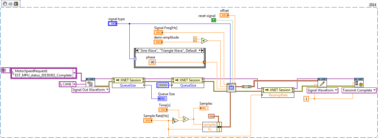
Size of the queue for Signal form write XNET
Hello
I am using the XNET library to play a preset on an output signal waveform. I work with LabVIEW 2014 SP1, 14.5 XNET on a W7 Pro 32-bit operating system. I use an NI PCI-8512 map. This is my first app using the xnet library.
In my test application, I give the user the ability to set the waveform to play. The total duration and the sampling frequency can be set. The output MAY report is cyclical, with a cycle time of 0.01 s (10 Hz). I chose to use the same frequency for example my wave form and writing of the CAN.
I have difficulty working with the size of the queue. In this example, it's good but I did not really why. I tested different values in the size of the queue and 100000 seems to be good up to 60 seconds. But for the longest (about 5 minutes), this method is not good...
What is the right way to work in this mode and how use efficiently the property size queue? Information and example of using software and hardware OR XNET are not very convincing...
Thank you in advance!
You can add several items at the end of the queue until the queue is empty. So if you want to write 10,000 points, and your buffer is only 1000 points, then wait and monitor the number of messages remaining in the buffer, and once it is less than 100 say adds an another 900.
I used this method for flashing on CAN and LIN. I needed a way to watch specific at specified times images, and a single point of frame link would not repeat (which could write the same byte twice what would be bad) I could have made the rivers and used avoiding, but a better solution was to use queue and add more pictures at the end of the queue to try to keep it as complete as possible.
-
output signals of the rectangle a PEAK sine wave conversion
Hello
I have a question on the treatment of a PIC16F84 output signals. It seems that the simulation of Multisim does not work properly - but before I blame Multisim, I ask the community NOR or software engineers or a solution. Because I'm German, you are invited to continue this thread in German if it is allowed by the rules of the forum. If you need additional information to analyze my problem, I'll be happy to provide.
The circuit itself has to convert "composition by pulse" signals "tone" (DTMF tones). So you can get old, classic phones work on new devices that do not support the "composition of pulse" more.
The circuit is powered by the analog telephone line current loop line. The PIC is provided by a rudimentary voltage regulation and count pulse signals (voltage failures / power interruption on the telephone line). After that the captain means the series of impulses in their equal number (e.g. 3 pulses = number 3). The captain gives finally two signals with different frequencies to generate a DTMF tone (e.g. number 3 here is 697 and 1477Hz). As you can see in my PDF file attached, it works very well.
Now I have to convert the rectangle wave given by the captain to an at least similar to a sine wave form - otherwise the device that receives the DTMF tones won't understand them.
So I connected a low-pass filter at the output of the PIC. Now, expect the rectangle signal to be smooth in a way as the 'e-function' will (loading / discharging a capacitor through a resistor). But the results are very far from that - as you can see I have very strange curves.
When I implemented a frequency generator with the same output signal as the PEAK and the low pass filter even I get curves as expected.
So we can say that the output of the PIC works like a frequency generator in my circuit. But why does the filter not behave as it should?
I've tried a lot of different values for the parameters of my RC-filter and simulation - this does not solve the problem.
It would be nice if someone has any idea how to solve this problem.
Thank you.
The output impedance of the PEAK may be too high. May be that my car 50 output? Try scaling of impedance of the filter. Do the 10000 ohms resistance and capacitor 10 nF.
Lynn
-
I have a wave form field which has a range of the axis y from 0 to 127. It is important that the plot goes from 0 to 127. The problem is normally the device I am able 127 statements for most of the conditions. I currently use a land line to the Base style but as lines go from the top of the list down. Unfortunately there is no apparent way to get a line style to the top.
I have attached my plot. As you can see, I want the lines to go from the top down.
Here is my code to set the style of the waveformPlot (linemode is true):
waveformPlot4.FillBase = XYPlotFillBase.YValue;
waveformPlot4.ToolTipsEnabled = true;
waveformPlot4.DefaultStart = lowerLimit;
waveformPlot4.DefaultIncrement = spacing;
waveformPlot4.YAxis = axis3;waveformPlot4.PointStyle = PointStyle.Cross;
waveformPlot4.PointColor = Color.Yellow;If (! lineMode)
{
waveformPlot4.FillMode = PlotFillMode.None;
waveformPlot4.LineColor = Color.Yellow;
}
on the other
{
waveformPlot4.FillMode = PlotFillMode.Lines;
waveformPlot4.LineColor = Color.Empty;
waveformPlot4.LineToBaseWidth = 1;
waveformPlot4.LineToBaseColor = Color.Yellow;
}Hello-
You're almost there - missing just one line. This should do it for you:
-
I have a 5661 DAMA. I have acquiredIQ of data on the FM band, i.e. 99 MHz I write it to a file. I get binaryfiles of data of different sizes depending on how long I have acquired data samplesof. I demodulate the data acquired using the FM.vi to demodulate MT. I want to be able to convert this demodulated data in a wave form of the file that I can PLAY and listen to this than the FM broadcast station.
Please guide me in the run.
Here is a code that you can work from.
I hope this helps.
-
Hello I'm trying to create a VI that will generate a wave form of two tables 1 d, one for the amplitude of a section of the wave and the other for the length of this article. For example, if I put in [1,2,3] in the table of amplitude and [2,5,10] in the table, I would get a graph that had a range of 1 to 2 seconds, then the amplitude 2 for 5 seconds, then aplitude 3 for 10 seconds. I use the function add a wave form to do this.
I have a VI that generates the amplitudes correctly, but delays do not work, each amplitude is true that for a second a piece, no matter what I put in the table of late. Anyone have any suggestions on how to force the amplitudes to be active for a given amount of time?
I have attached a picture of my code so far.
Thank you
I think this will do what you are looking for.

-
wave shot through of shunt dc motor
Hello
We have an application where the positive of a power source is connected to a shunt and the other end of the shunt is connected to the positive DC fan engine.
If a CRO is connected through the shunt, it shows a sine wave form. We want to replace this CRO with Labview software that allows to capture this waveform for analysis more away from ingredients using some materials preferably a USB based. We have labview 2009 version running on windows 7, 32 bit.
We are not sure if the material can be used since the motor is inductive and as soon as the power is turned on, it gives a peak. So we need assistance regarding if any material OR can be used directly in the system.
Thank you
Rohit
An important consideration is that these systems is the possibility of ground loops. The mass of the engine system and patterns of DAQ system can have enough impedance current heights in the engine, mainly because of defects, can cause enough voltage difference damage the measuring equipment or disrupt the measures.
Very rarely a direct connection to a shunt resistor is a good idea with loads of engine.
Consider using an isolated DAQ of entry device, an amplifier for instrumentation isolated between the valve and the data acquisition system or a single Hall effect current sensor. I used the devices of the series Allegro Microsystems ACS (> 2 kV isolation) on a few projects.
Lynn
-
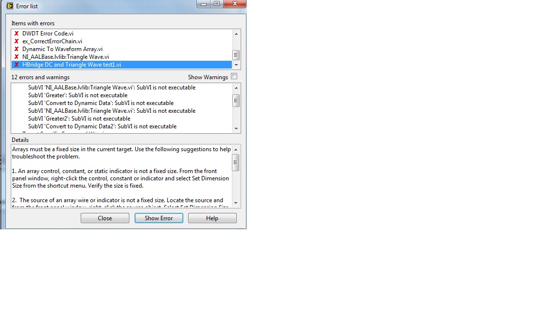
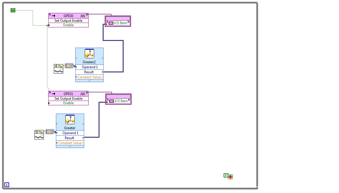
triangle wave in comparison questions
Hi all, I'm very new to using labview and have encountered a problem.
I'm trying to compare 2 ongoing tensions with a triangle wave form, in a manner similar to PWM comparing a triangle wave to sine wave. I am building the schema to load on an FPGA but can't with the wires going to the comparator leave the signal generator of triangle and in the interface of e/s of the element of comparison.
I think the problem is that the waveform of the triangle is an array, which is not a correct entry for the comparison group. I thought that the block that converts the table to the dynamic entry might solve this problem, but it didn't.
Attached images of the schematic list and error. Again I am really new to this. Thanks for any help
Right. FPGA does not allow tables (unless the length is set to a constant), or DDT. You will notice that if you open the palette of functions while editing an FPGA .vi, they aren't "even appear. The error message is that the subVIs cannot run.
Check it out Finder example OR (Help menu/search examples...) and search for "PWM". There are several examples, the first one (generation PWM) probably applies very well (use a caller .vi and pass something like [1000 + 1000 * sin (i)], and [1000-1000 * sin (i)] and change [F] to [T] to stop the time each cycle). Discover the other examples. There may be one more like what you want.
In general, the FPGA code works by a loop very quickly and treatment only one value at a time. Instead of generating a sine wave together and a triangle wave model, you must generate a single point in waves each pass through the loop.
If you want your own solution (instead of starting with the example): on the palette of functions, use 'search' to find sinus (or sinusoidal generator FPGA), etc. and use a normal programming/digital/Greater to compare the sine to triangle.
-
Rectifier of waveform or thresholding to form VL
Hi all
I just started using Labview so please bear with me.
I want to convert a waveform generated from an entry in an equivalent digital/square wave with only two values of Y by defining an analog threshold value. I was trying to index in the table of the original waveform of the values Y and check this value compared to the threshold value. If the value is less than the threshold value and then change the 0 value to a constant value of constantly changing otherwise.I struggled to generate square wave form I was looking for.
I'm not sure what a loop to use (while, for, or nested). I have a while loop on the spot because I expect a continuous stream of analog input data to convert.
Is there a similar vi there that I could mention?
Thank you!
He would do something like this:
Maybe you are looking for
-
Pavilion 500-436NA: HDMI on Pavilion 500-436NA?
Hi, just a quick question. Looking to buy HP Pavilion 500-436NA and I can't seem to find if it has a HDMI port within the specification. Someone can confirm if I did or not. Sorry if this seems a silly question. I'm not very 'cranky '. Thank you
-
When you try to build an application, I get the following error code: Error 15 took place at the signing of CodeSignAPI.lvlib:Get error String.vi Possible reasons: Error: The time stamp authority URL specified does not point to a valid authority time
-
I am trying to acquire data from a ni9222 located in the chassis-9014 9114, cRIO. But for some reason, the output data type is used as a 24-bit fixed point number? However the 9222 is module of the ADC 4 channels 16-bit 500ks/S. I want to run the dat
-
I have a HP 1606DN we want to offer to another part of our society. The 1606DN retains / previous Dungeon printed / scanned jobs? If Yes, how do print them and how do I get rid of them in memory?